31. ABS (ANTILOCK BRAKE SYSTEM)
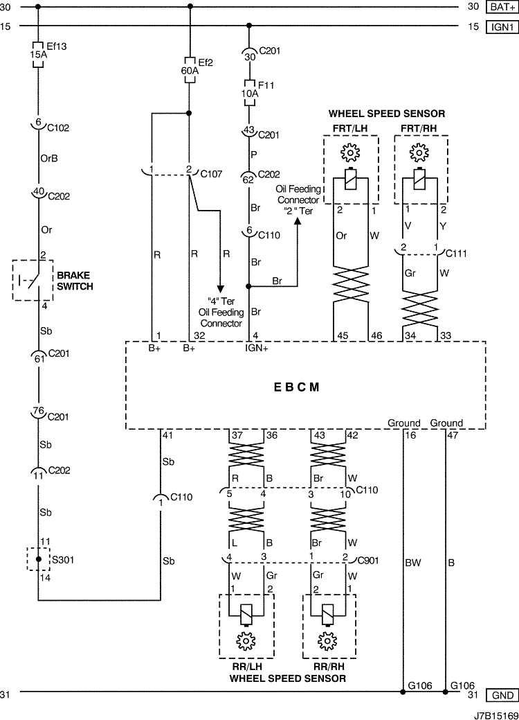
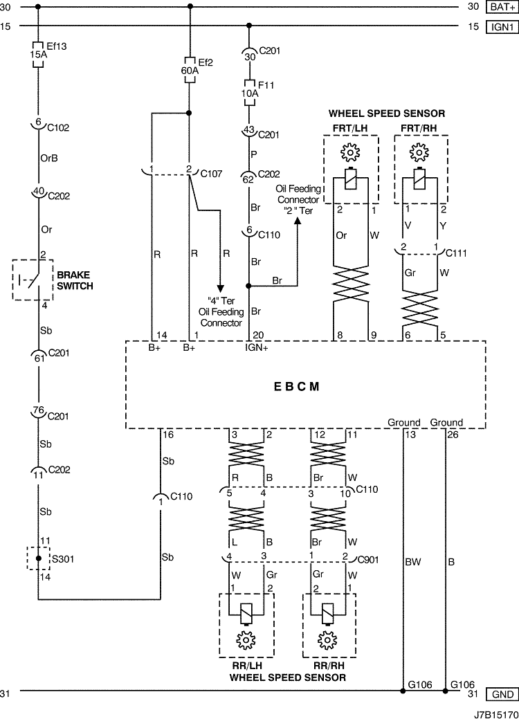
1) POWER SUPPLY, WHEEL SPEED SENSOR & BRAKE SWITCH CIRCUIT : W/ TCS
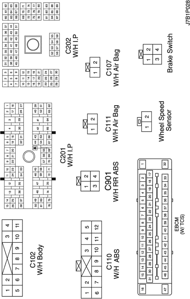
a. CONNECTOR INFORMATION
CONNECTOR NO
(PIN NO, COLOR) |
CONNECTING WIRING HARNESS |
CONNECTOR POSITION |
| C102 (11 Pin, White) |
Body – Engine Fuse Block |
Engine Fuse Block |
| C107 (2 Pin, White) |
ABS – Engine Fuse Block |
Engine Fuse Block |
| C110 (12 Pin, White) |
ABS – Body |
Below Engine Fuse Block |
| C111 (2 Pin, Black) |
ABS – Front |
Below Engine Fuse Block |
| C201 (76 Pin, Black) |
I.P – I.P Fuse Block |
I.P Fuse Block |
| C202 (89 Pin, White) |
I.P – Body |
Left CO-Driver Leg Room |
| C901 (4 Pin, Black) |
RR. ABS – Body |
Center Rear Cross member |
| S301 (Blue) |
Body |
Left CO-Driver Leg Room |
| G106 |
ABS |
Below EBCM |
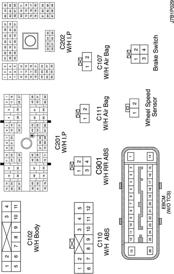
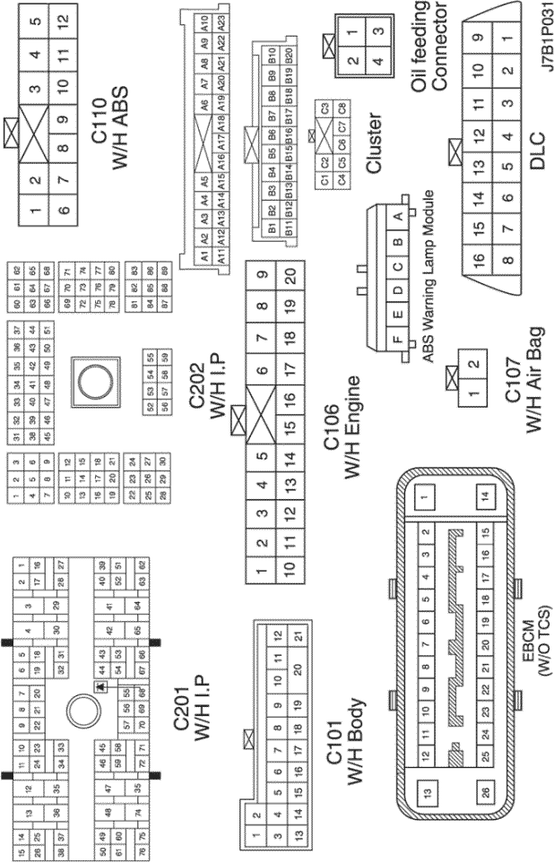
b. CONNECTOR IDENTIFICATION SYMBOL & PIN NUMBER POSITION
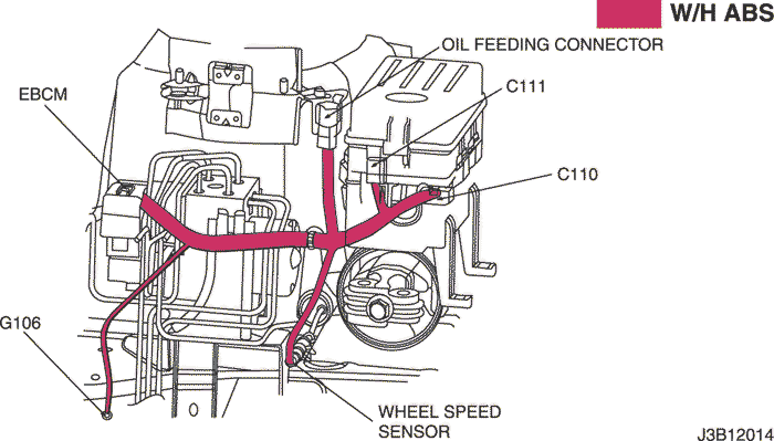
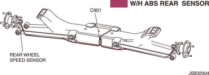
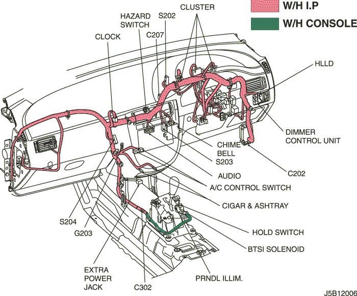
c. POSITION OF CONNECTORS AND GROUNDS
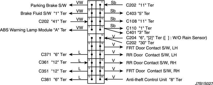
d. SPLICE PACK
S301 (NOTCH BACK)
S301 (HATCH BACK)
S301 (STATION WAGON)
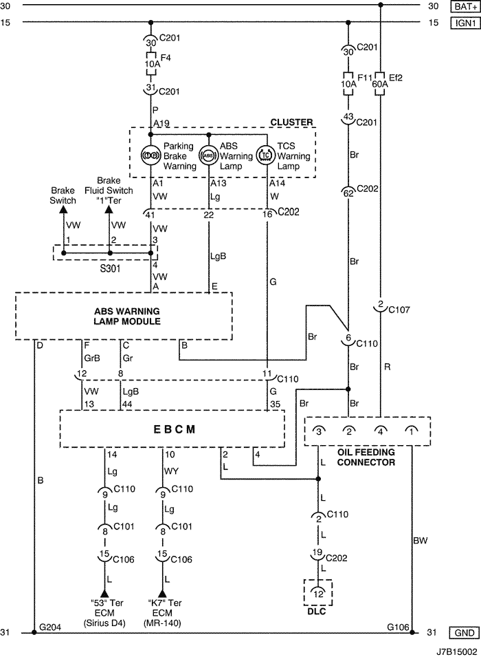
2) POWER SUPPLY, WHEEL SPEED SENSOR & BRAKE SWITCH CIRCUIT : W/O TCS
a. CONNECTOR INFORMATION
CONNECTOR NO
(PIN NO, COLOR) |
CONNECTING WIRING HARNESS |
CONNECTOR POSITION |
| C102 (11 Pin, White) |
Body – Engine Fuse Block |
Engine Fuse Block |
| C107 (2 Pin, White) |
ABS – Engine Fuse Block |
Engine Fuse Block |
| C110 (12 Pin, White) |
ABS – Body |
Below Engine Fuse Block |
| C111 (2 Pin, Black) |
ABS – Front |
Below Engine Fuse Block |
| C201 (76 Pin, Black) |
I.P – I.P Fuse Block |
I.P Fuse Block |
| C202 (89 Pin, White) |
I.P – Body |
Left CO-Driver Leg Room |
| C901 (4 Pin, Black) |
RR. ABS – Body |
Center Rear Cross member |
| S301 (Blue) |
Body |
Left CO-Driver Leg Room |
| G106 |
ABS |
Below EBCM |
b. CONNECTOR IDENTIFICATION SYMBOL & PIN NUMBER POSITION
c. POSITION OF CONNECTORS AND GROUNDS
d. SPLICE PACK
S301 (NOTCH BACK)
S301 (HATCH BACK)
S301 (STATION WAGON)
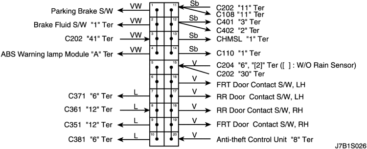
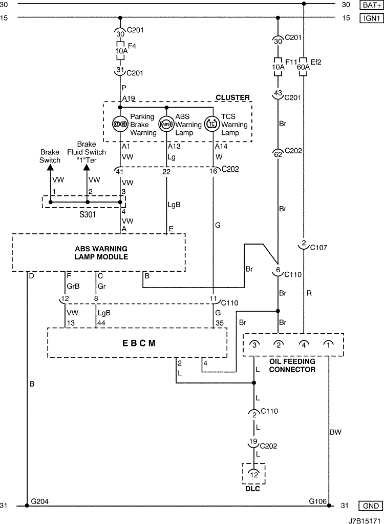
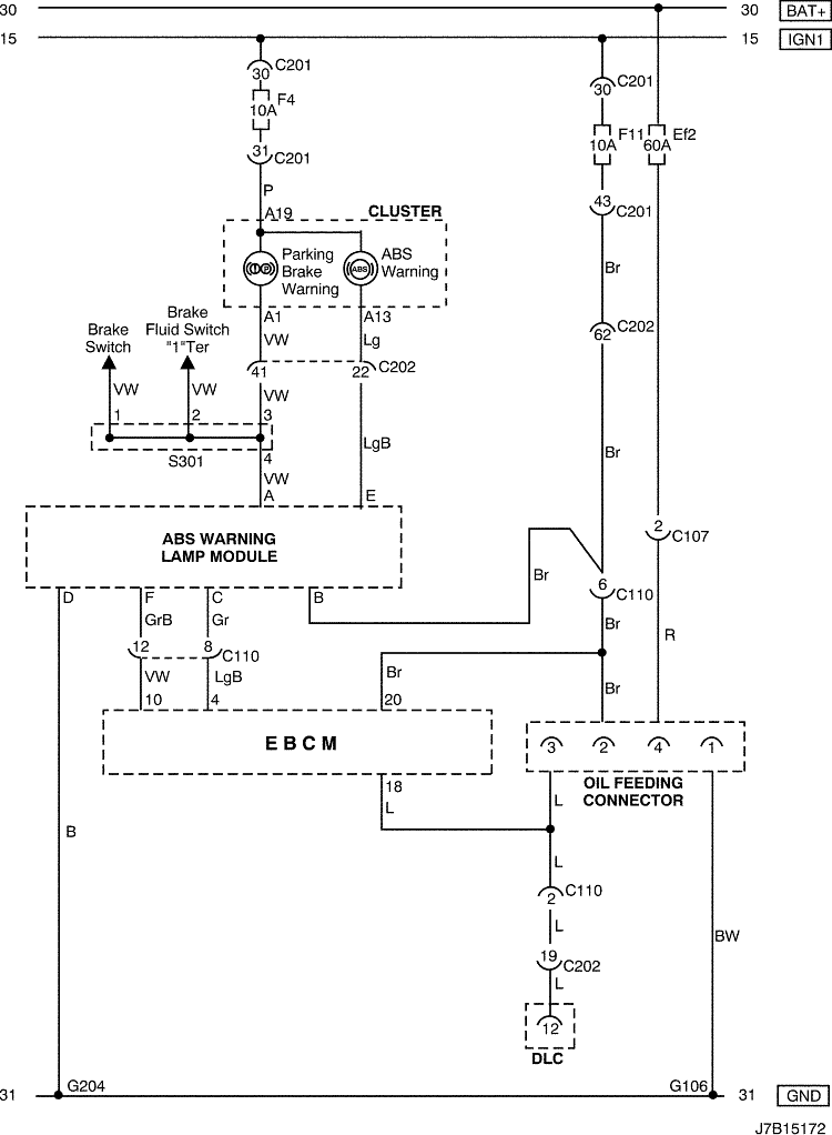
3) OIL FEEDING CONNECTOR, WARNING (ABS, TCS & BRAKE) LAMP & DLC CIRCUIT : W/ TCS (GASOLINE)
a. CONNECTOR INFORMATION
CONNECTOR NO
(PIN NO, COLOR) |
CONNECTING WIRING HARNESS |
CONNECTOR POSITION |
| C101 (21 Pin, White) |
Body – Engine Fuse Block |
Engine Fuse Block |
| C106 (20 Pin, White) |
Engine – Engine Fuse Block |
Engine Fuse Block |
| C107 (2 Pin, White) |
ABS – Engine Fuse Block |
Engine Fuse Block |
| C110 (12 Pin, White) |
ABS – Body |
Below Engine Fuse Block |
| C201 (76 Pin, Black) |
I.P – I.P Fuse Block |
I.P Fuse Block |
| C202 (89 Pin, White) |
I.P – Body |
Left CO-Driver Leg Room |
| S301 (Blue) |
Body |
Left CO-Driver Leg Room |
| G106 |
ABS |
Below EBCM |
| G204 |
Body |
Below Left CO-Driver Leg Room |
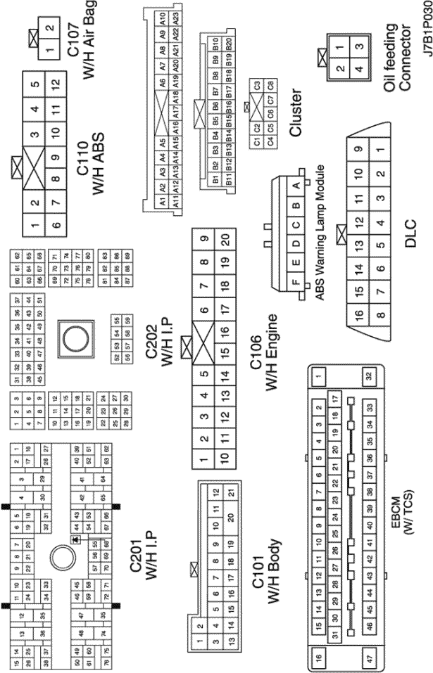
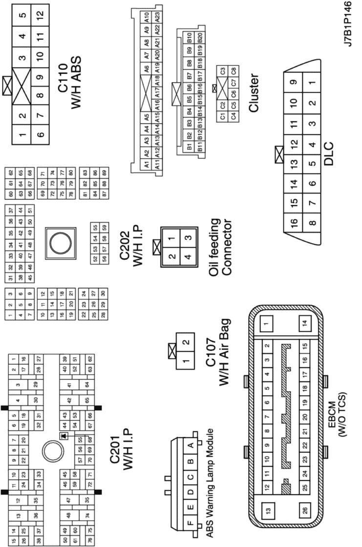
b. CONNECTOR IDENTIFICATION SYMBOL & PIN NUMBER POSITION
c. POSITION OF CONNECTORS AND GROUNDS
d. SPLICE PACK
S301 (NOTCH BACK)
S301 (HATCH BACK)
S301 (STATION WAGON)
4) OIL FEEDING CONNECTOR, WARNING (ABS, TCS & BRAKE) LAMP & DLC CIRCUIT : W/ TCS (DIESEL)
a. CONNECTOR INFORMATION
CONNECTOR NO
(PIN NO, COLOR) |
CONNECTING WIRING HARNESS |
CONNECTOR POSITION |
| C101 (21 Pin, White) |
Body – Engine Fuse Block |
Engine Fuse Block |
| C106 (20 Pin, White) |
Engine – Engine Fuse Block |
Engine Fuse Block |
| C107 (2 Pin, White) |
ABS – Engine Fuse Block |
Engine Fuse Block |
| C110 (12 Pin, White) |
ABS – Body |
Below Engine Fuse Block |
| C201 (76 Pin, Black) |
I.P – I.P Fuse Block |
I.P Fuse Block |
| C202 (89 Pin, White) |
I.P – Body |
Left CO-Driver Leg Room |
| S301 (Blue) |
Body |
Left CO-Driver Leg Room |
| G106 |
ABS |
Below EBCM |
| G204 |
Body |
Below Left CO-Driver Leg Room |
b. CONNECTOR IDENTIFICATION SYMBOL & PIN NUMBER POSITION
c. POSITION OF CONNECTORS AND GROUNDS
d. SPLICE PACK
S301 (NOTCH BACK)
S301 (HATCH BACK)
S301 (STATION WAGON)
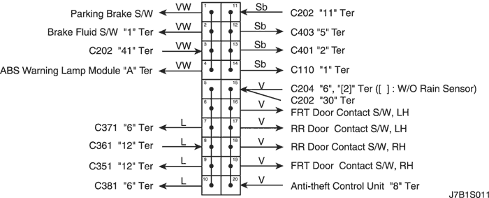
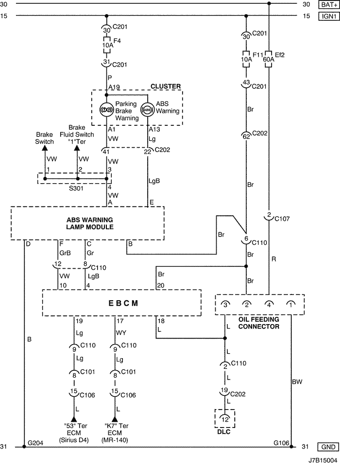
5) OIL FEEDING CONNECTOR, WARNING (ABS & BRAKE) LAMP & DLC CIRCUIT : W/O TCS (GASOLINE)
a. CONNECTOR INFORMATION
CONNECTOR NO
(PIN NO, COLOR) |
CONNECTING WIRING HARNESS |
CONNECTOR POSITION |
| C101 (21 Pin, White) |
Body – Engine Fuse Block |
Engine Fuse Block |
| C106 (20 Pin, White) |
Engine – Engine Fuse Block |
Engine Fuse Block |
| C107 (2 Pin, White) |
ABS – Engine Fuse Block |
Engine Fuse Block |
| C110 (12 Pin, White) |
ABS – Body |
Below Engine Fuse Block |
| C201 (76 Pin, Black) |
I.P – I.P Fuse Block |
I.P Fuse Block |
| C202 (89 Pin, White) |
I.P – Body |
Left CO-Driver Leg Room |
| S301 (Blue) |
Body |
Left CO-Driver Leg Room |
| G106 |
ABS |
Below EBCM |
| G204 |
Body |
Below Left CO-Driver Leg Room |
b. CONNECTOR IDENTIFICATION SYMBOL & PIN NUMBER POSITION
c. POSITION OF CONNECTORS AND GROUNDS
d. SPLICE PACK
S301 (NOTCH BACK)
S301 (HATCH BACK)
S301 (STATION WAGON)
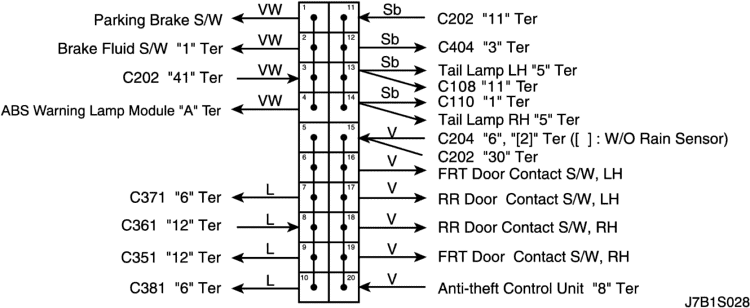
6) OIL FEEDING CONNECTOR, WARNING (ABS & BRAKE) LAMP & DLC CIRCUIT : W/O TCS (DIESEL)
a. CONNECTOR INFORMATION
CONNECTOR NO
(PIN NO, COLOR) |
CONNECTING WIRING HARNESS |
CONNECTOR POSITION |
| C107 (2 Pin, White) |
ABS – Engine Fuse Block |
Engine Fuse Block |
| C110 (12 Pin, White) |
ABS – Body |
Below Engine Fuse Block |
| C201 (76 Pin, Black) |
I.P – I.P Fuse Block |
I.P Fuse Block |
| C202 (89 Pin, White) |
I.P – Body |
Left CO-Driver Leg Room |
| S301 (Blue) |
Body |
Left CO-Driver Leg Room |
| G106 |
ABS |
Below EBCM |
| G204 |
Body |
Below Left CO-Driver Leg Room |
b. CONNECTOR IDENTIFICATION SYMBOL & PIN NUMBER POSITION
c. POSITION OF CONNECTORS AND GROUNDS
d. SPLICE PACK
S301 (NOTCH BACK)
S301 (HATCH BACK)
S301 (STATION WAGON)
| © Copyright Chevrolet Europe. All rights reserved |