5. ECM (ENGINE CONTROL MODULE) : EDC16C39 (DIESEL)
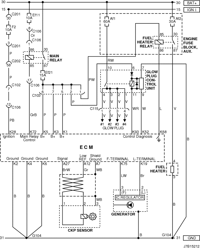
1) BATTERY, POWER SUPPLY, GROUND, GLOW PLUG CONTROL UNIT, FUEL HEATER, CKP SENSOR & GENERATOR CIRCUIT
a. CONNECTOR INFORMATION
CONNECTOR NO
(PIN NO, COLOR) |
CONNECTING WIRING HARNESS |
CONNECTOR POSITION |
| C102 (11 Pin, White) |
Body – Engine Fuse Block |
Engine Fuse Block |
| C103 (10 Pin, White) |
Engine – Engine Fuse Block |
Engine Fuse Block |
| C106 (20 Pin, White) |
Engine – Engine Fuse Block |
Engine Fuse Block |
| C115 (4 Pin, Black) |
Engine - Glow Plug (Diesel) |
Left Side Upper Cylinder |
| C201 (76 Pin, Black) |
I.P – I.P Fuse Block |
I.P Fuse Block |
| C202 (89 Pin, White) |
I.P – Body |
Left Driver Leg Room |
| G104 |
Engine |
Under Start Motor |
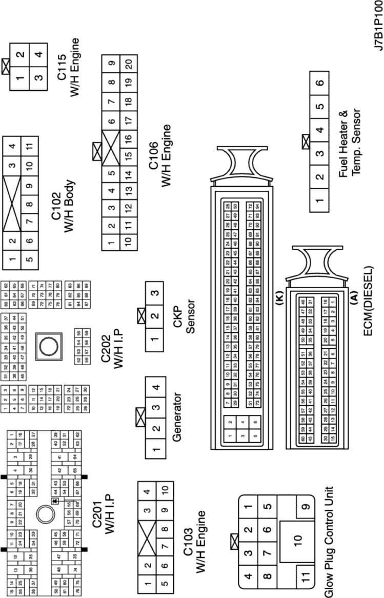
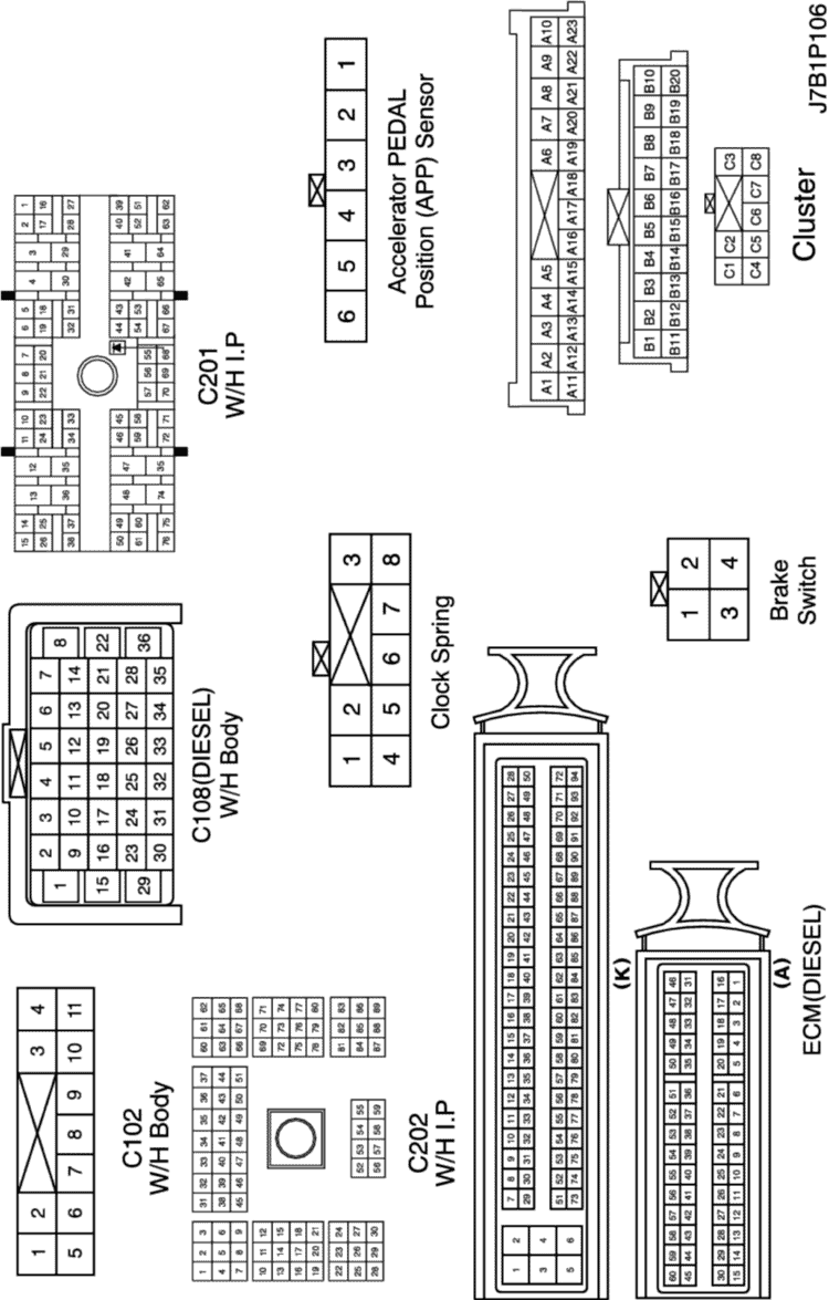
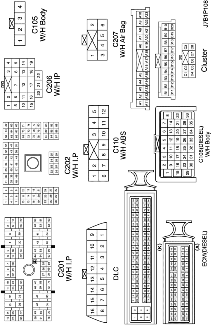
b. CONNECTOR IDENTIFICATION SYMBOL & PIN NUMBER POSITION
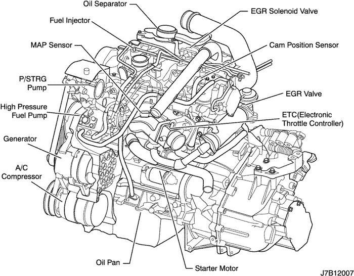
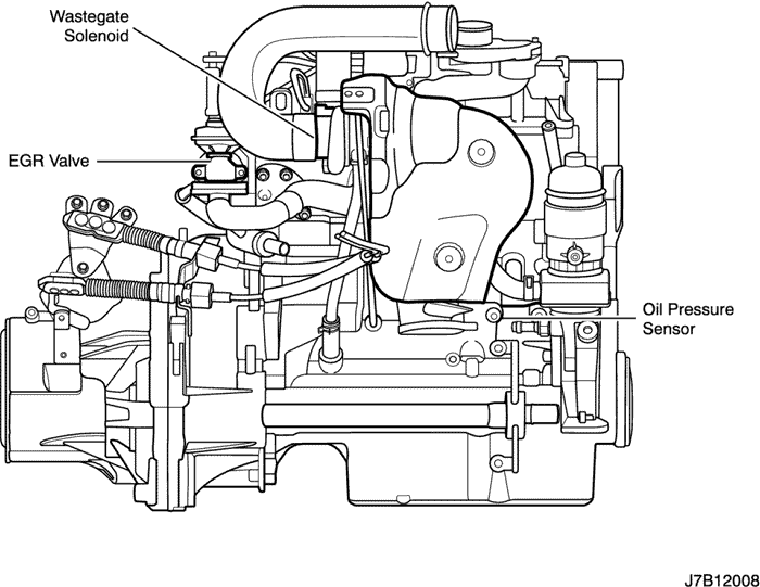
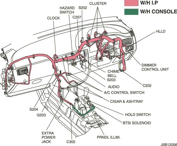
c. POSITION OF CONNECTORS AND GROUNDS
DIESEL
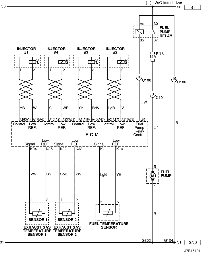
2) INJECTOR, EXHASUT GAS TEMPERATURE SENSOR, FUEL TEMPERATURE SENSOR & FUEL PUMP CIRCUIT
a. CONNECTOR INFORMATION
CONNECTOR NO
(PIN NO, COLOR) |
CONNECTING WIRING HARNESS |
CONNECTOR POSITION |
| C101 (21 Pin, White) |
Body – Engine Fuse Block |
Engine Fuse Block |
| C106 (20 Pin, White) |
Engine – Engine Fuse Block |
Engine Fuse Block |
| G104 |
Engine |
Under Start Motor |
| G302 |
Body |
Below Left C Pillar |
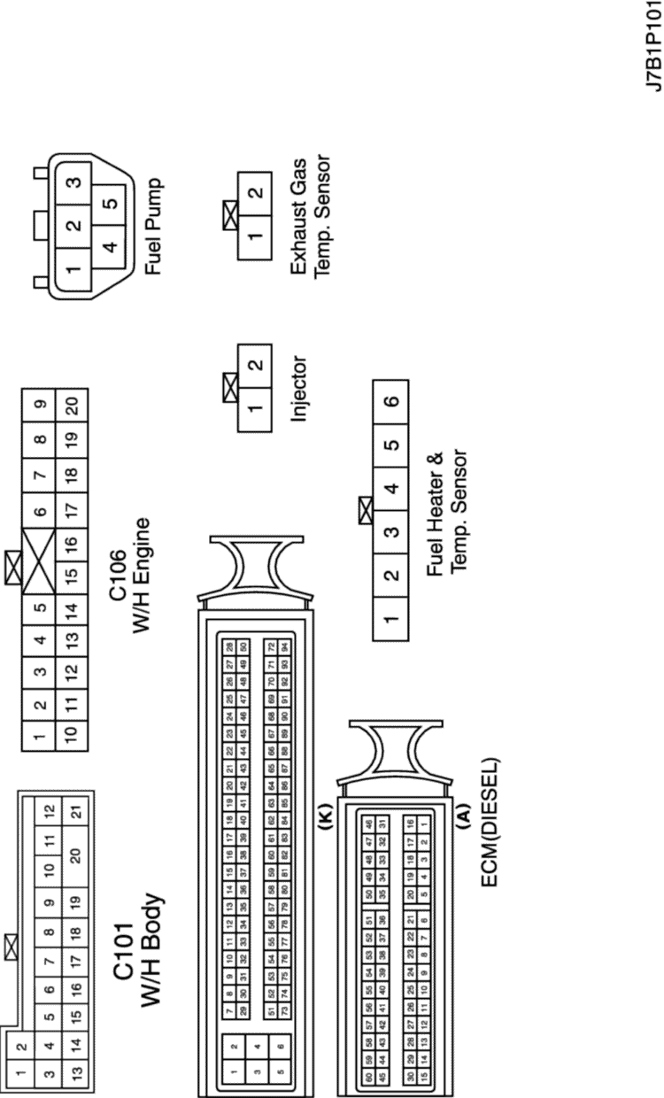
b. CONNECTOR IDENTIFICATION SYMBOL & PIN NUMBER POSITION
c. POSITION OF CONNECTORS AND GROUNDS
DIESEL
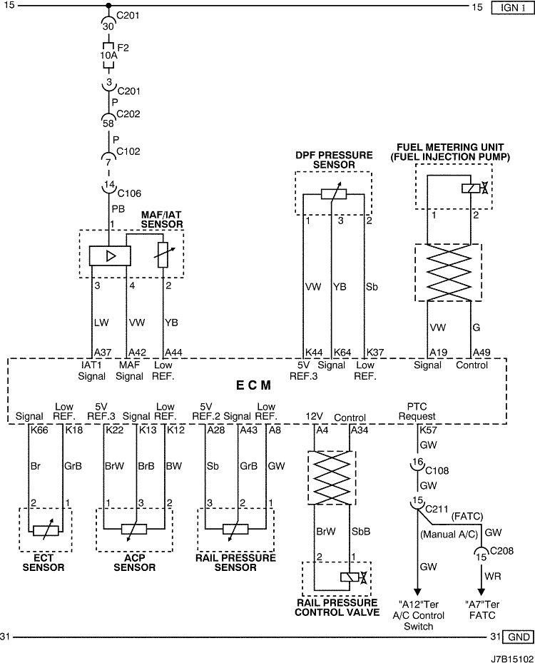
3) SENSOR (MAF/IAT, DPF, ECT, ACP, RAIL PRESSURE), FUEL METERING UNIT & RAIL PRESSURE CONTROL VALVE CIRCUIT
a. CONNECTOR INFORMATION
CONNECTOR NO
(PIN NO, COLOR) |
CONNECTING WIRING HARNESS |
CONNECTOR POSITION |
| C102 (11 Pin, White) |
Body – Engine Fuse Block |
Engine Fuse Block |
| C106 (20 Pin, White) |
Engine – Engine Fuse Block |
Engine Fuse Block |
| C108 (36 Pin, Black) |
Body - Engine (Diesel) |
Left Engine Fuse Block |
| C201 (76 Pin, Black) |
I.P – I.P Fuse Block |
I.P Fuse Block |
| C202 (89 Pin, White) |
I.P – Body |
Left Driver Leg Room |
| C208 (15 Pin, White) |
I.P - FATC |
Behind Glove Box |
| C211 (15 Pin, White) |
I.P - Body (Diesel) |
Left Driver Leg Room |
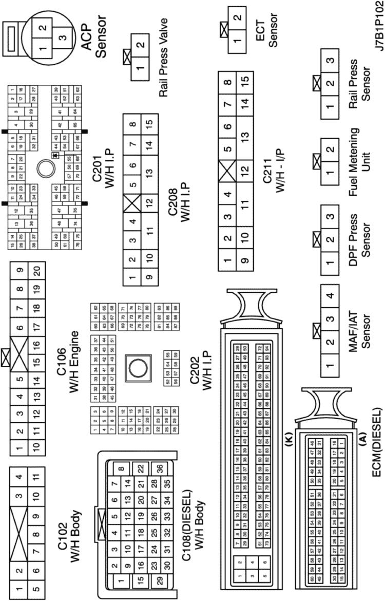
b. CONNECTOR IDENTIFICATION SYMBOL & PIN NUMBER POSITION
c. POSITION OF CONNECTORS AND GROUNDS
DIESEL
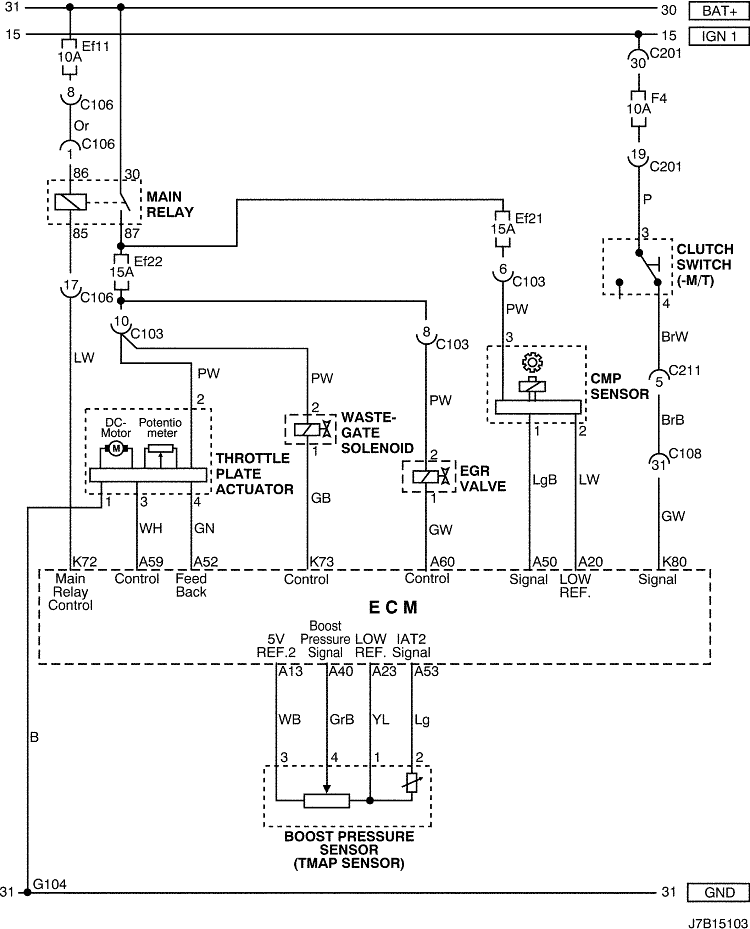
4) THROTTLE PLATE ACTUATOR, WASTEGATE SOLENOID, CMP SENSOR, CLUTCH SWITCH, EGR VALVE & BOOST PRESSURE SENSOR CIRCUIT
a. CONNECTOR INFORMATION
CONNECTOR NO
(PIN NO, COLOR) |
CONNECTING WIRING HARNESS |
CONNECTOR POSITION |
| C103 (10 Pin, White) |
Engine – Engine Fuse Block |
Engine Fuse Block |
| C106 (20 Pin, White) |
Engine – Engine Fuse Block |
Engine Fuse Block |
| C108 (36 Pin, Black) |
Body - Engine (Diesel) |
Left Engine Fuse Block |
| C201 (76 Pin, Black) |
I.P – I.P Fuse Block |
I.P Fuse Block |
| C211 (15 Pin, White) |
I.P - Body (Diesel) |
Left Driver Leg Room |
| G104 |
Engine |
Under Start Motor |
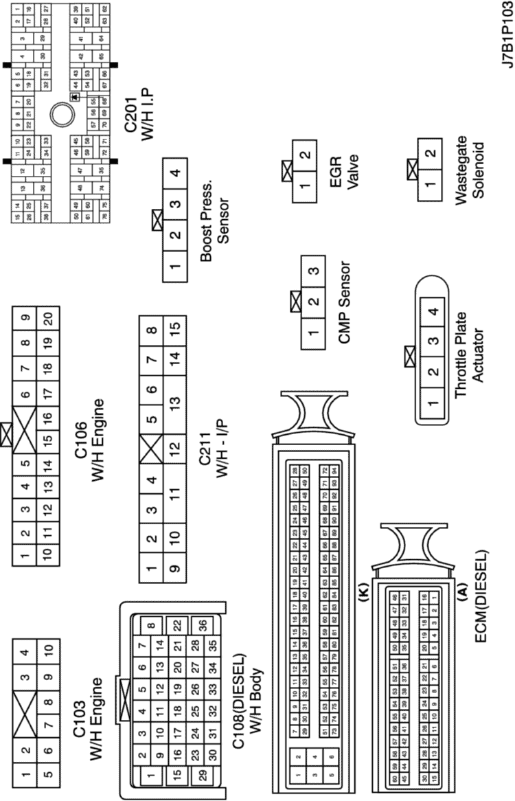
b. CONNECTOR IDENTIFICATION SYMBOL & PIN NUMBER POSITION
c. POSITION OF CONNECTORS AND GROUNDS
DIESEL
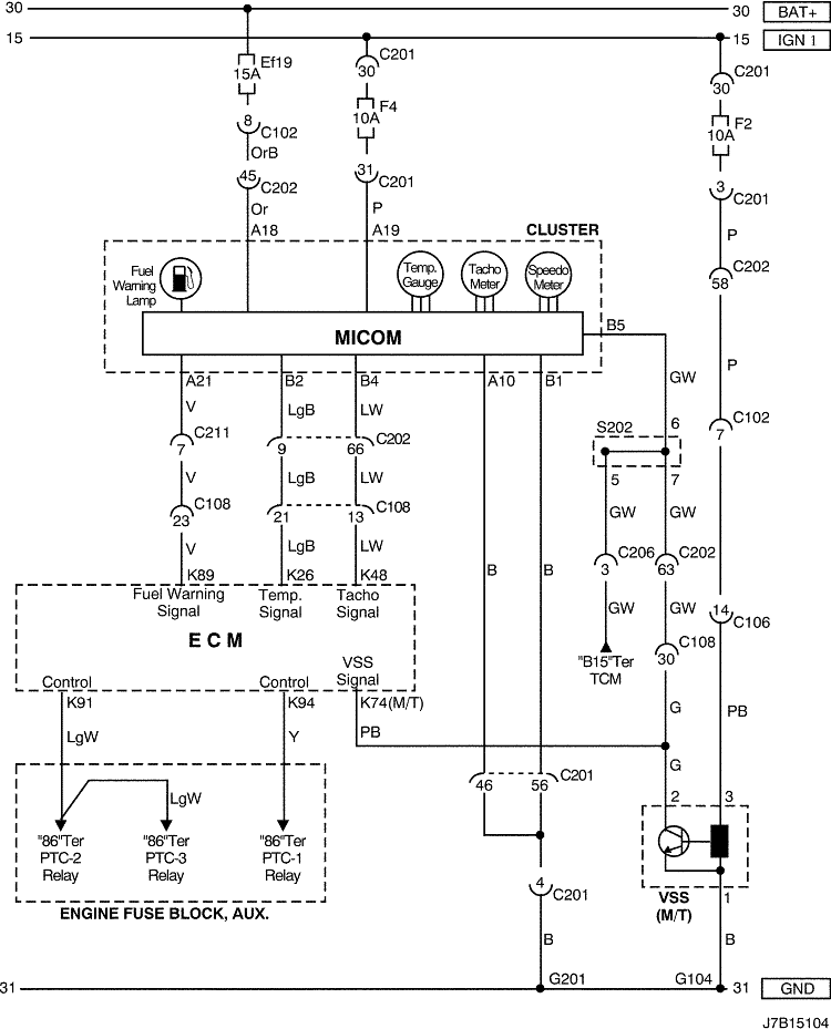
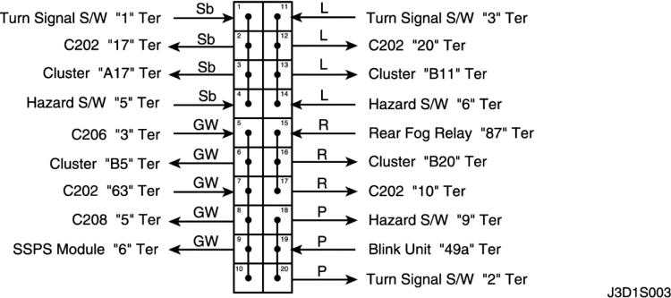
5) CLUSTER & VEHICLE SPEED CIRCUIT
a. CONNECTOR INFORMATION
CONNECTOR NO
(PIN NO, COLOR) |
CONNECTING WIRING HARNESS |
CONNECTOR POSITION |
| C102 (11 Pin, White) |
Body – Engine Fuse Block |
Engine Fuse Block |
| C104 (24 Pin, White) |
Front - Engine Fuse Block |
Engine Fuse Block |
| C106 (20 Pin, White) |
Engine – Engine Fuse Block |
Engine Fuse Block |
| C108 (36 Pin, Black) |
Body - Engine (Diesel) |
Left Engine Fuse Block |
| C201 (76 Pin, Black) |
I.P – I.P Fuse Block |
I.P Fuse Block |
| C202 (89 Pin, White) |
I.P – Body |
Left Driver Leg Room |
| C206 (22 Pin, White) |
I.P - TCM |
Upper Driver Leg Room |
| C211 (15 Pin, White) |
I.P - Body (Diesel) |
Left Driver Leg Room |
| S202 (Black) |
I.P |
Behind Cluster |
| G104 |
Engine |
Under Start Motor |
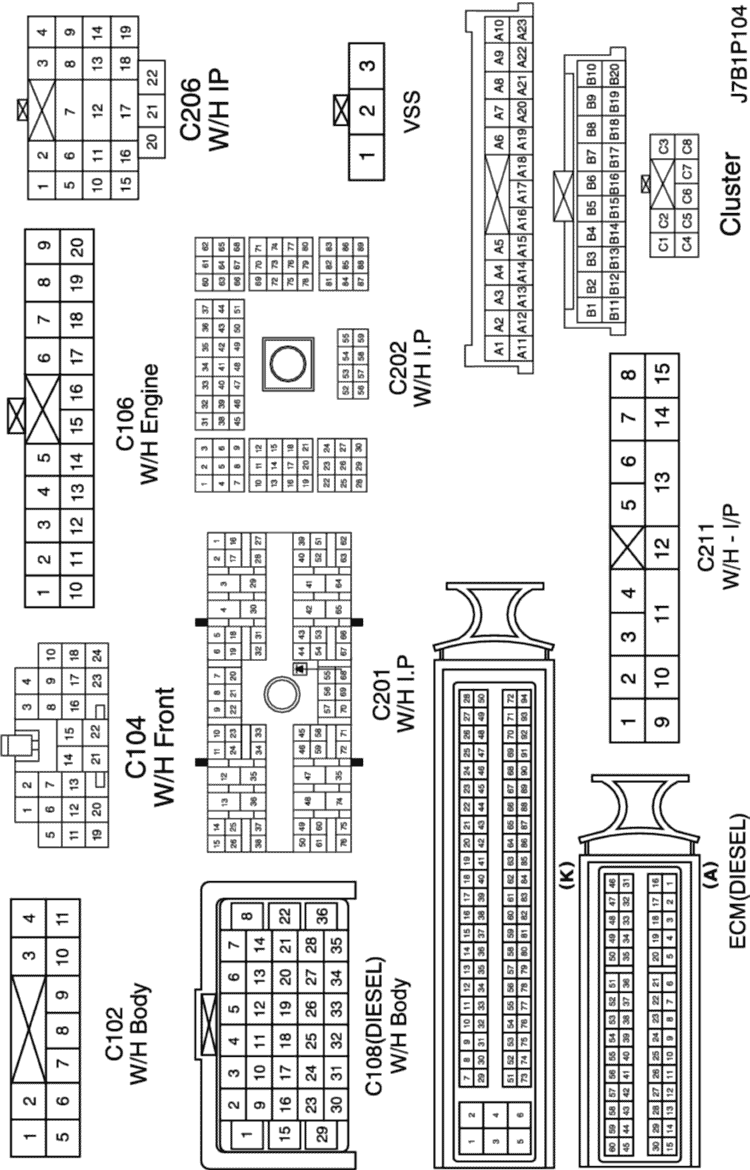
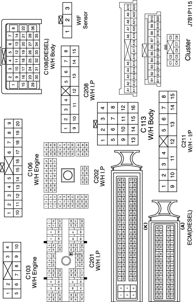
b. CONNECTOR IDENTIFICATION SYMBOL & PIN NUMBER POSITION
c. POSITION OF CONNECTORS AND GROUNDS
DIESEL
d. SPLICE PACK
S202
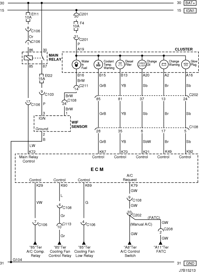
6) CLUSTER & WIF SENSOR CIRCUIT
a. CONNECTOR INFORMATION
CONNECTOR NO
(PIN NO, COLOR) |
CONNECTING WIRING HARNESS |
CONNECTOR POSITION |
| C103 (10 Pin, White) |
Engine – Engine Fuse Block |
Engine Fuse Block |
| C106 (20 Pin, White) |
Engine – Engine Fuse Block |
Engine Fuse Block |
| C108 (36 Pin, Black) |
Body - Engine (Diesel) |
Left Engine Fuse Block |
| C113 (16 Pin, Black) |
Body - Front |
Behind ECM Bracket |
| C201 (76 Pin, Black) |
I.P – I.P Fuse Block |
I.P Fuse Block |
| C202 (89 Pin, White) |
I.P – Body |
Left Driver Leg Room |
| C208 (15 Pin, White) |
I.P- FATC |
Behind Glove Box |
| C211 (15 Pin, White) |
I.P - Body (Diesel) |
Left Driver Leg Room |
| G104 |
Engine |
Under Start Motor |
b. CONNECTOR IDENTIFICATION SYMBOL & PIN NUMBER POSITION
c. POSITION OF CONNECTORS AND GROUNDS
DIESEL
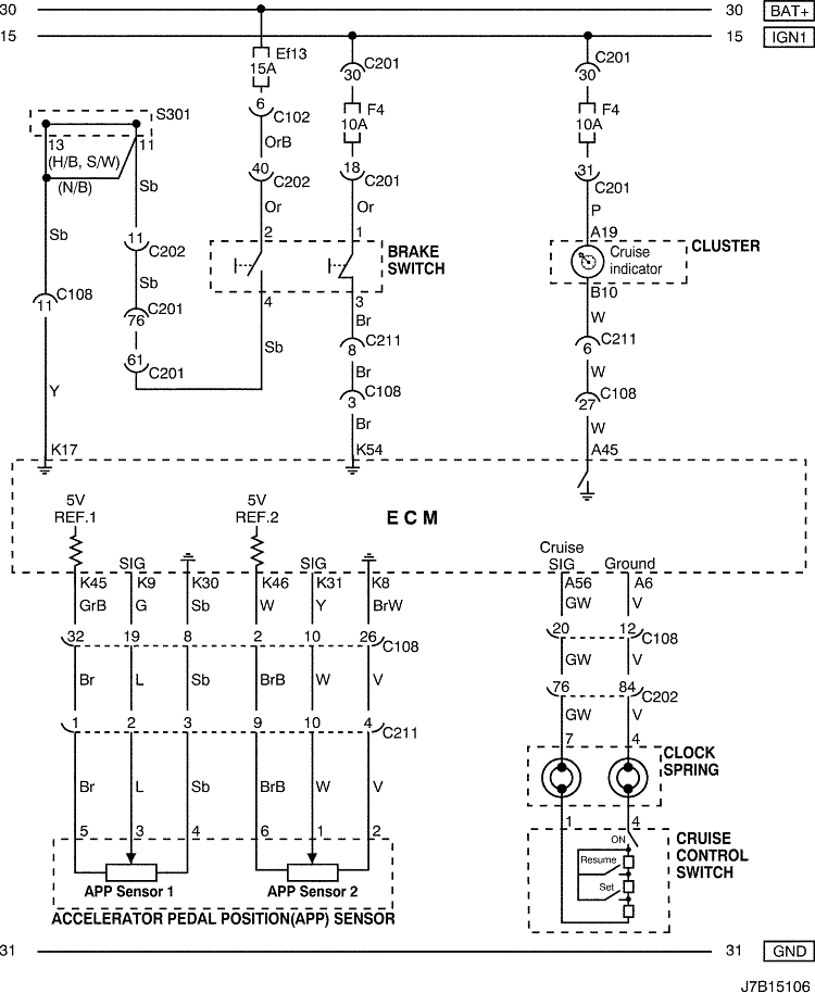
7) BRAKE SWITCH, APP SENSOR & CRUISE CONTROL CIRCUIT
a. CONNECTOR INFORMATION
CONNECTOR NO
(PIN NO, COLOR) |
CONNECTING WIRING HARNESS |
CONNECTOR POSITION |
| C102 (11 Pin, White) |
Body – Engine Fuse Block |
Engine Fuse Block |
| C108 (36 Pin, Black) |
Body - Engine (Diesel) |
Left Engine Fuse Block |
| C201 (76 Pin, Black) |
I.P – I.P Fuse Block |
I.P Fuse Block |
| C202 (89 Pin, White) |
I.P – Body |
Left Driver Leg Room |
| S301 (Blue) |
Body |
Left Driver Leg Room |
b. CONNECTOR IDENTIFICATION SYMBOL & PIN NUMBER POSITION
c. POSITION OF CONNECTORS AND GROUNDS
d. SPLICE PACK
S301 (BLUE) : NOTCH BACK
S301 (BLUE) : HATCH BACK
S301 (BLUE) : STATION WAGON
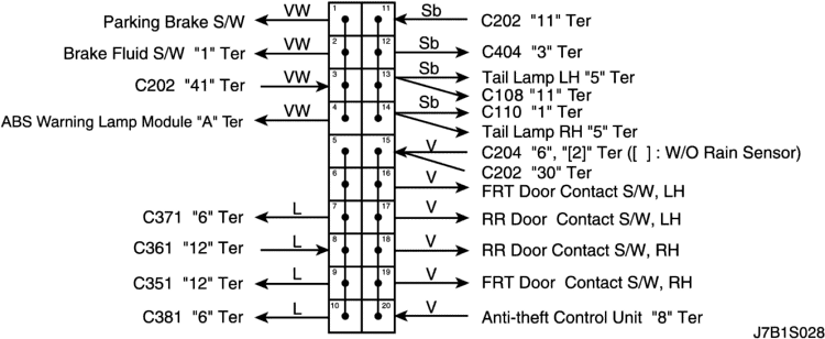
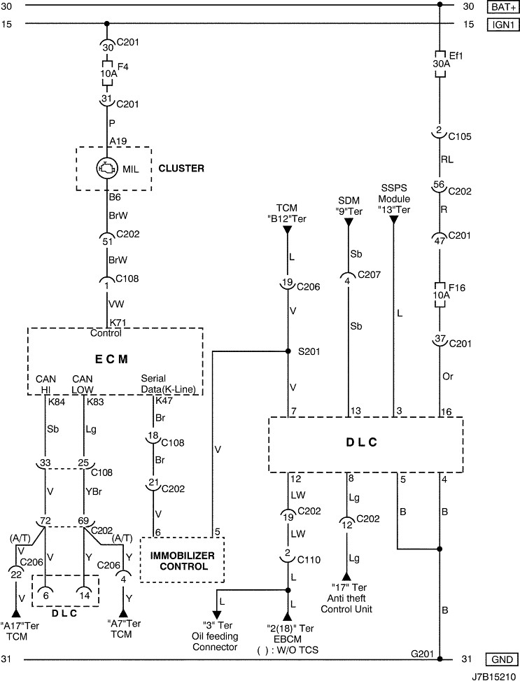
8) DLC, MIL LAMP & IMMOBILIZER CONTROL CIRCUIT: W/ IMMOBILIZER
a. CONNECTOR INFORMATION
CONNECTOR NO
(PIN NO, COLOR) |
CONNECTING WIRING HARNESS |
CONNECTOR POSITION |
| C105 (4 Pin, White) |
Body – Engine Fuse Block |
Engine Fuse Block |
| C108 (36 Pin, Black) |
Body - Engine (Diesel) |
Left Engine Fuse Block |
| C110 (12 Pin, White) |
ABS – Body |
Below Engine Fuse Block |
| C201 (76 Pin, Black) |
I.P – I.P Fuse Block |
I.P Fuse Block |
| C202 (89 Pin, White) |
I.P – Body |
Left Driver Leg Room |
| C206 (22 Pin, White) |
I.P – TCM |
Upper Driver Leg Room |
| C207 (6 Pin, White) |
Air Bag – I.P |
Upper Right Driver Leg Room |
| G201 |
I.P |
Left I.P Fuse Block |
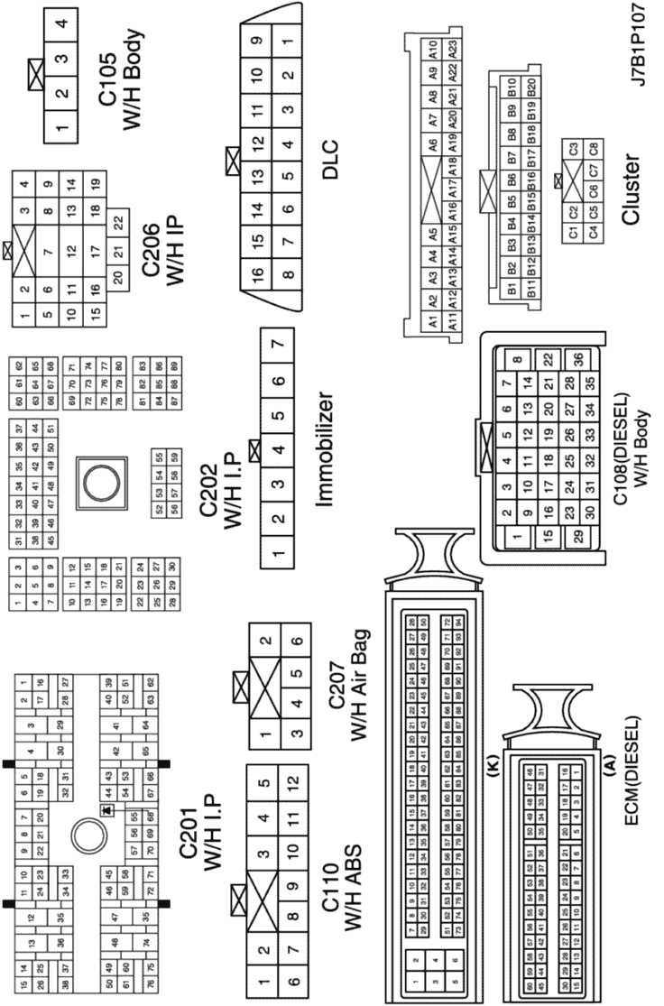
b. CONNECTOR IDENTIFICATION SYMBOL & PIN NUMBER POSITION
c. POSITION OF CONNECTORS AND GROUNDS
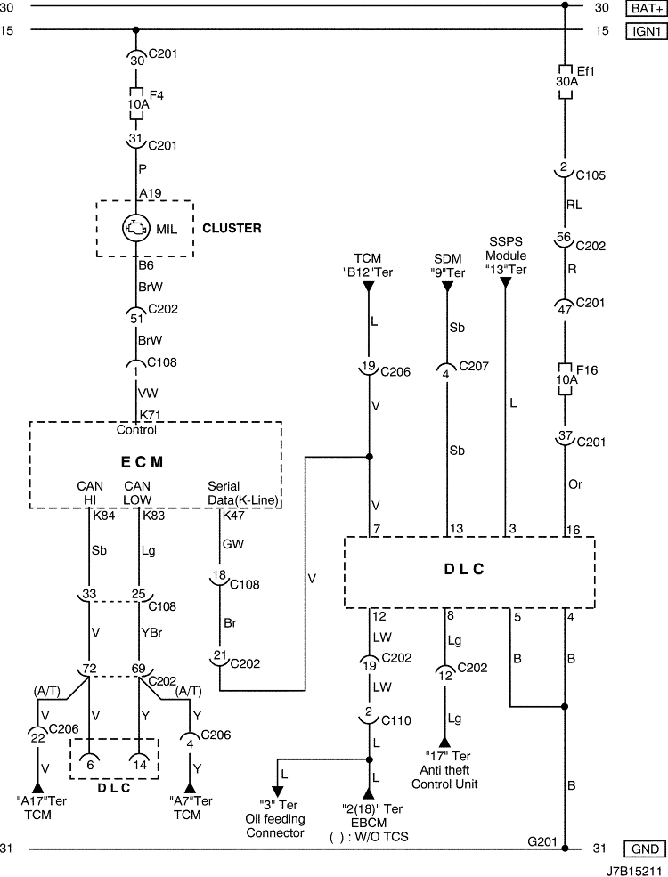
9) DLC & MIL LAMP CIRCUIT: W/O IMMOBILIZER
a. CONNECTOR INFORMATION
CONNECTOR NO
(PIN NO, COLOR) |
CONNECTING WIRING HARNESS |
CONNECTOR POSITION |
| C105 (4 Pin, White) |
Body – Engine Fuse Block |
Engine Fuse Block |
| C108 (36 Pin, Black) |
Body - Engine (Diesel) |
Left Engine Fuse Block |
| C110 (12 Pin, White) |
ABS – Body |
Below Engine Fuse Block |
| C201 (76 Pin, Black) |
I.P – I.P Fuse Block |
I.P Fuse Block |
| C202 (89 Pin, White) |
I.P – Body |
Left Driver Leg Room |
| C206 (22 Pin, White) |
I.P – TCM |
Upper Driver Leg Room |
| C207 (6 Pin, White) |
Air Bag – I.P |
Upper Right Driver Leg Room |
| G201 |
I.P |
Left I.P Fuse Block |
b. CONNECTOR IDENTIFICATION SYMBOL & PIN NUMBER POSITION
c. POSITION OF CONNECTORS AND GROUNDS
| © Copyright Chevrolet Europe. All rights reserved |