SECTION 3B
REAR DRIVE AXLE
SPECIFICATIONS
General Specifications
Application | Unit | Description |
Clutch Coupling Assembly Operation voltage | Volt | 9 ~ 16 |
Clutch Coupling Assembly Operation temp. range | °C | -40 ~ +100 |
Coupling Torque Capacity | N•m | 1,000 |
Rear Axle Gear Ratio | - | 2.53 |
Max. Rear Axle Output Torque | N•m | 2,530 |
Fluid Information | - | Texaco Synthetic Fuel Efficient Hypoid P/N:89021677 |
Thread sealent | - | GM P/N 12346004 (Canadian P/N 10953480) |
Total Fluid Capacity | Liter | 0.6 ± 0.1 |
Fastener Tightening Specifications
Application | N•m | Lb-Ft | Lb-In |
Propeller shaft to PTU flange bolts | 25 | 19 | - |
Propeller shaft to RDM flange bolts | 50 | 37 | - |
Propeller shaft support bearing mounting bolts | 25 | 19 | - |
Lower control arm to knuckle bolt and nut | 160 | 118 | - |
Trailing arm bracket to underbody bolt | 110 | 81 | - |
Toe link to knuckle nut and bolt | 160 | 118 | - |
Knuckle to upper control arm nut and bolt | 160 | 118 | - |
Differential carrier assemblt side bracket securing bolts | 29 | 21 | - |
Clutch coupling assembly housing securing bolts | 26 | 19 | - |
Pinion flange nut(of RDM) | 203 | 150 | - |
Coupling control module securing bolts | 10 | 7 | - |
Front securing bolts of RDM | 117 | 86 | - |
Front/rear securing bolts of RDM | 180 | 133 | - |
Fill/drain plug | 42 | 31 | - |
SPECIAL TOOLS
Special Tools Table
 
| J-8059 Snap Ring Pliers |
| DT-48254 Rear wheel drive shaft seal Installer |
SCEMATIC AND ROUTING DIAGRAMS
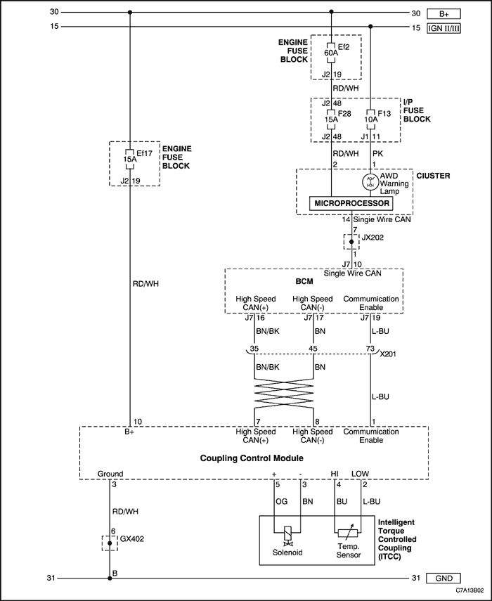
Rear Drive Module(RDM) Circuit
COMPONENT LOCATOR
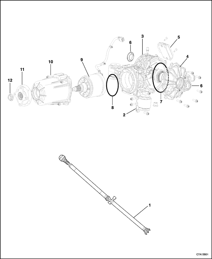
Rear Drive Axle
- Propeller Shaft
- Differential Carrier Assembly Side Bracket
- Differential Carrier Assembly
- Differential Carrier Assembly Side Cover
- Coupling Control Module
- Rear Wheel Drive Shaft Seal
- Differential Carrier Assembly Side Cover Seal
- Differential Drive Pinion Gear Seal
- Clutch Coupling Assembly
- Clutch Coupling Assembly Housing
- Pinion Flange
- Pinion Flange Nut
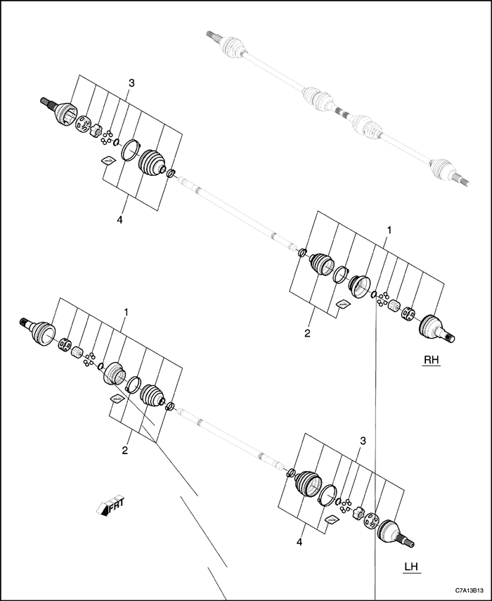
Wheel Drive Shaft - Rear
- Inboard Joint Kit
- Inboard Seal Kit
- Outboard Joint Kit
- Outboard Seal Kit
DIAGNOSIS
General Diagnosis
Visual/Physical Inspection
- Inspect for aftermarket devices, which could affect the operation of the vehicle.
- Inspect the easily accessible or visible system components for obvious damage or a condition which could cause the symptom.
- Check for correct lubricant level and proper viscosity.
- Verify the exact operating conditions under which the concerns exist. Note factors such as speed, road conditions, ambient temperature, and other specifics.
- Compare the driving characteristics or sounds, if applicable, to a known good vehicle and make sure you are not trying to correct a normal condition.
Notice : Do not exceed more than 5 seconds of parking brake application. RDM damage may result.
- Rear axle activation and operation may be checked by positioning the four wheels off the ground, starting the vehicle, and selecting the drive position. A properly operating rear axle and transfer case will rotate all four wheels at equal RPM. Fully apply the parking brake, the rear will stop turning. Apply the throttle while watching the rear wheels. They will rotate slightly as the driveline winds-up. This indicates the AWD is functioning.
- Factors that may contribute to an inoperative rear axle include:
A low gear oil level
A mini spare or different size tires
A fluid over-temperature condition
A defective rear axle assembly
An inoperative transfer case assembly
The wrong fluid type
Intermittents
Test the vehicle under the same conditions that the customer reported in order to verify the system is operating properly.
Noise Acceptability
A gear driven unit will produce a certain amount of noise. Some noise is acceptable and audible at certain speeds, or under various driving conditions, such as a newly-paved blacktop road. Slight noise is not detrimental to the operation of the axle and is considered normal.
Symptom List(Rear Drive Axle)
Refer to a symptom diagnostic procedure from the following list in order to diagnose the symptom:
- Noisy in Drive
- Noisy When Coasting
- Intermittent Noise
- Constant Noise
- Noisy on Turns
- Rear Axle Lubricant Leak Diagnosis
Noisy in Drive
Cause | Correction |
Inspect for proper gear oil levels prior to performing system diagnosis. |
Loose propeller shaft mounting bolts | Tighten the bolts as required. |
Worn propeller shaft constant velocity joint | Replace the propeller shaft assembly. A worn propeller shaft constant velocity joint may create a clicking, grinding, or snapping type noise. |
Worn axle shaft constant velocity joints | Replace/repair the axle shaft as required. A worn axle shaft constant velocity joint may create a clicking, grinding, or snapping type of noise. |
Worn or damaged Differential Housing Support bushings (side) | Replace bushings as required. A worn bushing may create a clunk type of noise during acceleration or deceleration. |
Worn or damaged Differential Housing Support bushings (rear) | Replace bushings as required. A worn bushing may create a clunk type of noise during acceleration or deceleration. Check bushing orientation; the tuning slots must be in proper position. |
Loose rear mounting bracket bolts | Tighten the bracket bolts as required. |
Loose or damaged prop guard | Repair or replace as required. A loose dust shield may contact the propeller shaft assembly and create a scraping or grinding type of noise. |
Gear set whine noise within Clutch Coupling Assembly | A whine type of noise will increase or decrease relative to the vehicle speed (approximately 80-90 km/h (50-56 mph)). Check for the proper fluid level. Repair or replace the unit as required. |
Shutter or moan at slow speeds or slow turns | A shutter or moan type of noise in slow sharp turns. RDM could be contaminated with the wrong fluid type/water. Replace the fluid; fill as required and retest under conditions. |
Noisy When Coasting
Cause | Correction |
Inspect for proper gear oil levels prior to performing system diagnosis. |
Loose propeller shaft mounting bolts | Tighten the bolts as required. |
Worn propeller shaft constant velocity joint. | Replace the propeller shaft assembly. A worn propeller shaft constant velocity joint may create a clicking, grinding, or snapping type of noise. |
Worn universal joints | Replace the propeller shaft assembly as required. A worn universal joint may create a clicking or a snapping type of noise. |
Worn or damaged Differential Housing Support mounting bushings (Side) | Check the bushing position and replace the bushings as required. A worn bushing may create a clunk type of noise during acceleration or deceleration or wrong orientation. |
Worn or damaged Differential Housing Support mounting bushings (Rear) | Replace the bushings as required. A worn bushing may create a clunk type of noise during acceleration or deceleration. |
Loose rear mounting bracket bolts | Tighten the bracket bolts as required. |
Loose or damaged prop guard | Repair or replace as required. A loose dust shield may contact the propeller shaft assembly and create a scraping or grinding type of noise. |
Bearing noise within RDM | A grinding roar type of noise will increase or decrease relative to the vehicle speed. Check for proper fluid level. If the noise continues, repair or replace the unit as required. |
Gear set whine noise within RDM created by incorrect gear backlash | A whine type of noise will increase or decrease relative to vehicle speed. - Check for the proper fluid level.
- Repair or replace the unit as required
|
Intermittent Noise
Cause | Correction |
Inspect for proper gear oil levels prior to performing system diagnosis. |
Low gear oil levels | Fill axle to the recommended level. A low level may create intermittent or incomplete clutch park engagement. |
Incorrect gear oil | Replace with gear oil, GM P/N 9986115. Incorrect gear oil may create improper clutch pack engagement or a slippage condition. |
Worn clutch pack oil pump | Replace the clutch coupling assembly. |
Worn clutch pack friction discs | Replace the clutch coupling assembly. |
Constant Noise
Cause | Correction |
Inspect for proper gear oil levels prior to performing system diagnosis. |
Low gear oil levels | Faulty oil seal or other types of leaks may contribute to lower than required fluid levels. Fill to the proper level with gear oil, GM P/N 9986115. |
Worn propeller shaft constant velocity or universal joints | If constant velocity joint is damaged, replace the propeller shaft. |
Bearing noise within Clutch Coupling Assembly | This type of noise will decrease or increase relative to the vehicle speed. - Check for the proper fluid level.
- Repair or replace the unit as required.
|
Gear set whine noise within RDM caused by incorrect backlash | A whine type of noise will increase or decrease relative to the vehicle speed. - Check for the proper fluid level.
- Repair or replace the unit as required.
|
Noisy on Turns
Cause | Correction |
Inspect for proper gear oil levels prior to performing system diagnosis. Operate the vehicle turning in tight circles, in both left and right directions. Moan, groan, chatter, or a pulsing type concern may indicate a pump or clutch park problem within the axle assembly. |
Worn or loose rear axle mount bolts | Repair or replace as required. |
Worn axle shaft constant velocity joints | Replace the axle shaft as required. |
Worn wheel bearings | Replace the wheel bearings as required. |
Incorrect gear oil | Replace with gear oil, GM P/N 9986115. |
Worn differential side and/or idler gears and worn cross-pin | Replace differential carrier assembly as required. |
Rear Axle Lubricant Leak Diagnosis
Cause | Correction |
Restricted or damaged ventilation tube assembly | Replace the ventilation tube as required. |
Leaking fill or drain plug | Install sealant, GM P/N 12346004 (Canadian P/N 10953480) or equivalent onto threads of plugs and tighten. |
Leaking input flange seal | - Inspect the input flange surface for excessive wear or damage.
- Inspect the front bearing for wear or damage. A worn bearing may allow excessive movement of the clutch pack input shaft.
- Replace the components as required.
|
Leaks at the housing sealing surfaces | Disassemble the axle and reseal the sealing surfaces as required - clutch drum cover only. |
Worn or damages axle shaft oil seals | Replace the axle shaft oil seals as required. |
Symptom List(Propeller Shaft)
Refer to a symptom diagnostic procedure from the following list in order to diagnose the symptom:
- Roughness or Vibration
- Ping, Snap, or Click Noise
- Knock or Clunk Noise
- Scraping Noise
- Squeak Noise
- Shudder on Acceleration at Low Speed
Roughness or Vibration
Cause | Correction |
The roughness or vibration occurs while driving the vehicle at various speeds. |
A bent or dented propeller shaft | Replace the propeller shaft. |
Undercoating is on the propeller shaft | - Clean the propeller shaft.
|
The universal joints are worn | Replace the propeller shaft Assembly because universal joint is not serviceable. |
The driveline vibration is at 80 km/h (50 mph) | Inspect propeller shaft for runout. |
Ping, Snap, or Click Noise
Cause | Correction |
A ping, snap, or click is usually heard on initial load after the transmission is in gear, either forward or reverse. |
Upper and lower control arms have loose bushing bolts. | Tighten bolts to specified torque. |
A loose fixed yoke or companion flange | - Tighten bolts and pinion nut to specified torque
|
Worn or damaged universal joint | Replace the propeller shaft Assembly because universal joint is not serviceable. |
The driveline vibration is at 80 km/h (50 mph) | Inspect propeller shaft for runout. |
Knock or Clunk Noise
Cause | Correction |
Knocking or clunking noise occurs when operating the vehicle in high gear or coasting in neutral at 16 km/h (10 mph). |
A worn or damaged universal joint | Replace the propeller shaft Assembly because universal joint is not serviceable. |
Scraping Noise
Cause | Correction |
A scraping noise occurs when driving the vehicle at various speeds. |
The pinion flange or center bearing is rubbing | Correct the interference. |
Squeak Noise
Cause | Correction |
When driving the vehicle at various speeds a squeaking sound occurs. |
Lack of lubricant | Replace the propeller shaft Assembly as required. |
Shudder on Acceleration at Low Speed
Cause | Correction |
When accelerating the vehicle at low speed a shudder occurs. |
Bolts are loose or missing at the flanges | Replace and/or tighten bolts to specified torque. |
The universal joint is worn | Replace the propeller shaft Assembly because universal joint is not serviceable. |
Diagnostic Trouble Code and Description
DTC | Decsription |
C0393(0B) | Rear Axle Coupling Solenoid Control Circuit(Over Current) |
C0393(06) | Rear Axle Coupling Solenoid Control Circuit(Wiring) |
C0394(06) | Rear Axle Coupling Solenoid Temperature Sensor Circuit |
C0550(35) | Electronic Control Unit(ECU) Performance(ROM) |
C0550(39) | Electronic Control Unit(ECU) Performance(Wiring) |
C0558(4B) | Calibration Data Not Programmed/Learned |
C0561(71) | System Permanently disabled Information Stored |
C0899(03) | Device{single or 1} Voltage Low |
U0100(00) | Lost Communication With Engine Control Module |
U0121(00) | Lost Communication With Anti-Lock Brake System(ABS) Control Module |
U0140(00) | Lost Communication With Body Control Module |
DTC C0393(0B)
Circuit Description
If more current conduction than preset value found by monitoring shunt current on coupling coil in the Clutch Coupling Assembly, the system will be permanently disabled.
DTC Descriptors
This diagnostic procedure supports the following DTCs:
- DTC C0393(0B) Rear Axle Coupling Solenoid Control Circuit(Over Current)
Conditions for Setting the DTC
All of the following must be true for C0393(0B) to set.
- Supply voltage is greater than 8 volt, the coil current is greater than 6volt and these conditions maintained over 40ms.
- Supply voltage is less than 8 volt and the coil current is greater than 6volt.
Action Taken When the DTC Sets
- DTC C0393(0B) is stored.
- AWD system permanently disabled, AWD warning lamp turns on.
Conditions for Clearing the DTC
- If the conditions that set DTC C0393(0B) is no longer present, the DTC may be cleared by using the proper scan tool.
- The DTC that has not occurred in 100 drive cycles will be cleared from history data.
DTC C0393(0B) - Rear Axle Coupling Solenoid Control Circuit(Over Current)
| Step | Action | Value(s) | Yes | No |
| 1 | Check the wiring harness, connector and terminals between the coupling control module and clutch coupling assembly. Is any physical damage noted? | - | Go to Step 2 | Go to Step 3 |
| 2 | Repair the damage and check the system using scan tool. Is any DTC noted? | - | Go to Step 3 | System ok |
| 3 | Replace the clutch coupling assembly. Perform the system calibration and check the system using scan tool. Is any DTC noted? | - | Go to Step 1 | System OK |
DTC C0393(06)
Circuit Description
When error detected from output PWM(Pulse Width Modulation) duty and shunt current inside of the Clutch Coupling Assembly upper coil, systems will be permanently disabled.
DTC Descriptors
This diagnostic procedure supports the following DTCs:
- DTC C0393(06) Rear Axle Coupling Solenoid Control Circuit(Wiring)
Conditions for Setting the DTC
All of the following must be true for C0393(06) to set.
- The PWM duty is greater than 90% and the coil current is less than 0.1A.
- The PWM duty is less than 10% and the coil current is greater than 3.0A.
- Supply voltage is greater than 8 volt, no over current error and these conditions maintained over 2s.
Action Taken When the DTC Sets
- DTC C0393(06) is stored.
- AWD system permanently disabled, AWD warning lamp turns on.
Conditions for Clearing the DTC
- If the conditions that set DTC C0393(06) is no longer present, the DTC may be cleared by using the proper scan tool.
- The DTC that has not occurred in 100 drive cycles will be cleared from history data.
DTC C0393(0B) - Rear Axle Coupling Solenoid Control Circuit(Over Current)
| Step | Action | Value(s) | Yes | No |
| 1 | Check the wiring harness, connector and terminals between the coupling control module and clutch coupling assembly. Is any physical damage noted? | - | Go to Step 2 | Go to Step 3 |
| 2 | Repair the damage and check the system using scan tool. Is any DTC noted? | - | Go to Step 3 | System ok |
| 3 | Replace the coupling control module. Perform the system calibration and check the system using scan tool. Is any DTC noted? | - | Go to Step 1 | System OK |
DTC C0394(06)
Circuit Description
In case of Clutch Coupling Assembly temperature signal error, substitute value(-20 degree Celsius) is applied for control and DTC is memorized.
DTC Descriptors
This diagnostic procedure supports the following DTCs:
- DTC C0394(06) Rear Axle Coupling Solenoid Temperature Sensor Circuit
Conditions for Setting the DTC
All of the following must be true for C0394(06) to set.
- The Coupling temperature sensor voltage is greater than 4.5volt and maintained over 10s.
- The Coupling temperature sensor voltage is less than 0.015volt and maintained over 10s.
Action Taken When the DTC Sets
- DTC C0394(06) is stored.
- AWD system permanently disabled, AWD warning lamp turns on.
Conditions for Clearing the DTC
- If the conditions that set DTC C0394(06) is no longer present, the DTC may be cleared by using the proper scan tool.
- The DTC that has not occurred in 100 drive cycles will be cleared from history data.
DTC C0394(06) - Rear Axle Coupling Solenoid Temperature Sensor Circuit
| Step | Action | Value(s) | Yes | No |
| 1 | Check the wiring harness, connector and terminals(terminal 4,2 of the coupling control module) between the coupling control module and clutch coupling assembly. Is any physical damage noted? | - | Go to Step 2 | Go to Step 3 |
| 2 | Repair the damage and check the system using scan tool. Is any DTC noted? | - | Go to Step 3 | System ok |
| 3 | Replace the clutch coupling assembly. Perform the system calibration and check the system using scan tool. Is any DTC noted? | - | Go to Step 1 | System OK |
DTC C0550(35)
Circuit Description
Add all the ROM values to see if the result of bottom byte would be ‘A5H’.
Process when any these errors occurred: CCM(Coupling Control Module) will enter Stop Mode immediately.
DTC Descriptors
This diagnostic procedure supports the following DTCs:
- DTC C0550(35) Electronic Control Unit(ECU) Performance(ROM)
Conditions for Setting the DTC
- The CCM ROM failed, the result of bottom byte is not ‘A5H’.
Action Taken When the DTC Sets
- DTC C0550(35) is stored.
- AWD system permanently disabled, AWD warning lamp turns on.
Conditions for Clearing the DTC
- If the conditions that set DTC C0550(35) is no longer present, the DTC may be cleared by using the proper scan tool.
- The DTC that has not occurred in 100 drive cycles will be cleared from history data.
DTC C0550(35) - Electronic Control Unit(ECU) Performance(ROM)
| Step | Action | Value(s) | Yes | No |
| 1 | Check the wiring harness, connector and terminals between the coupling control module and clutch coupling assembly. Is any physical damage noted? | - | Go to Step 2 | Go to Step 3 |
| 2 | Repair the damage and check the system using scan tool. Is any DTC noted? | - | Go to Step 3 | System ok |
| 3 | Replace the coupling control module. Perform the system calibration and check the system using scan tool. Is any DTC noted? | - | Go to Step 1 | System OK |
DTC C0550(39)
Circuit Description
When relay junction welding defect and relay junction contact defect found by monitoring supply voltage before/after relay ON command, system will be permanently disabled.
DTC Descriptors
This diagnostic procedure supports the following DTCs:
- DTC C0550(39) Electronic Control Unit(ECU) Performance(Wiring)
Conditions for Setting the DTC
- While primary checking, Relay OFF output Supply voltage is greater than 9volt, No over current error and these conditions maintained over 1s.
- While primary checking, Relay ON output Supply voltage is less than 2volt, No over current error and these conditions maintained over 5s.
Action Taken When the DTC Sets
- DTC C0550(39) is stored.
- AWD system permanently disabled, AWD warning lamp turns on.
Conditions for Clearing the DTC
- If the conditions that set DTC C0550(39) is no longer present, the DTC may be cleared by using the proper scan tool.
- The DTC that has not occurred in 100 drive cycles will be cleared from history data.
DTC C0550(39) - Electronic Control Unit(ECU) Performance(Wiring)
| Step | Action | Value(s) | Yes | No |
| 1 | Check the wiring harness, connector and terminals between the coupling control module and clutch coupling assembly. Is any physical damage noted? | - | Go to Step 2 | Go to Step 3 |
| 2 | Repair the damage and check the system using scan tool. Is any DTC noted? | - | Go to Step 3 | System ok |
| 3 | Replace the coupling control module. Perform the system calibration and check the system using scan tool. Is any DTC noted? | - | Go to Step 1 | System OK |
DTC C0558(4B)
Circuit Description
When an ECU does not have I-T(Current-Torque) characteristic adjustment data for each coupling, max torque will be limited.
DTC Descriptors
This diagnostic procedure supports the following DTCs:
- DTC C0558(4B) Calibration Data Not Programmed/Learned
Conditions for Setting the DTC
- CCM(Coupling Control Module) calibration process in the plant hasn't been completed.
Action Taken When the DTC Sets
- DTC C0558(4B) is stored.
- AWD system permanently disabled, AWD warning lamp turns on.
Conditions for Clearing the DTC
- If the conditions that set DTC C0558(4B) is no longer present, the DTC may be cleared by using the proper scan tool.
- The DTC that has not occurred in 100 drive cycles will be cleared from history data.
DTC C0550(39) - Electronic Control Unit(ECU) Performance(Wiring)
| Step | Action | Value(s) | Yes | No |
| 1 | In case of the coupling control module replacement or clutch coupling assembly replacement, perform the system calibration and check the system using scan tool. Is any DTC noted? | - | Go to Step 2 | System OK |
| 2 | Perform the appropriate DTC diagnostic procedure. | - | - | - |
DTC C0561(71)
Circuit Description
In case of Accelerator signal error, Command torque will be controlled by wheel speed signals and DTC is memorized.
DTC Descriptors
This diagnostic procedure supports the following DTCs:
- DTC C0561(71) System Permanently disabled Information Stored
Conditions for Setting the DTC
- When ECU received invalid signal and the condition maintained for 500 ms.
Action Taken When the DTC Sets
- DTC C0561(71) is stored.
- AWD system temporarily disabled, AWD warning lamp blinks.
Conditions for Clearing the DTC
- If the conditions that set DTC C0561(71) is no longer present, the DTC may be cleared by using the proper scan tool.
- The DTC that has not occurred in 100 drive cycles will be cleared from history data.
DTC C0561(71) - System Permanently disabled Information Stored
| Step | Action | Value(s) | Yes | No |
| 1 | - Check the accelerator pedal position sensor, ECM(Engine Control Module) and the related wiring harness. Refer to Section 1F3, Engine Controls-Controls HFV6 3.2L.
- Check the system using scan tool.
Is any DTC noted? | - | Go to Step 2 | System ok |
| 2 | - Check the wheel speed sensor, EBCM(Electronic Brake Control Module) and the related wiring harness. Refer to Section 4F, ABS.
- Check the system using scan tool.
Is any DTC noted? | - | Go to Step 3 | System ok |
| 3 | Replace the coupling control module. Perform the system calibration and check the system using scan tool. Is any DTC noted? | - | Go to Step 1 | System OK |
DTC C0899(03)
Circuit Description
When low Battery voltage and relay junction contact defect found by monitoring supply voltage after relay setup, system will be disabled.
DTC Descriptors
This diagnostic procedure supports the following DTCs:
- DTC C0899(03) Device{single or 1} Voltage Low
Conditions for Setting the DTC
- After system setup, relay ON output, supply voltage is less than 5volt, No over current error and these conditions maintained over 30s.
Action Taken When the DTC Sets
- DTC C0899(03) is stored.
- AWD system temporarily disabled, AWD warning lamp blinks.
Conditions for Clearing the DTC
- If the conditions that set DTC C0899(03) is no longer present, the DTC may be cleared by using the proper scan tool.
DTC C0899(03) - Device{single or 1} Voltage Low
| Step | Action | Value(s) | Yes | No |
| 1 | - Check the battery and generator. Refer to section 1E3, Engine Electrical HFV6 3.2L.
- Check the system using scan tool.
Is any DTC noted? | - | Go to Step 2 | System ok |
| 2 | - Check the fuse Ef17, terminal 19 of connector J2 from the engine fuse block.
- Check the wiring harness between the terminal 19 of connector J2 and terminal 10 of the coupling control module.
- Check the system using scan tool.
Is any DTC noted? | - | Go to Step 3 | System ok |
| 3 | - Replace the coupling control module.
- Perform the system calibration and check the system using scan tool.
Is any DTC noted? | - | Go to Step 1 | System OK |
DTC U0100(00)
Circuit Description
In case of ECM signal missing, Command torque is controled by wheel speed signals and DTC is memorized.
DTC Descriptors
This diagnostic procedure supports the following DTCs:
- DTC U0100(00) Lost Communication With ECM(Engine Control Module)
Conditions for Setting the DTC
- “Engine Speed” signal cannot be received in 500 ms.
Action Taken When the DTC Sets
- DTC U0100(00) is stored.
- AWD system temporarily disabled, AWD warning lamp blinks.
Conditions for Clearing the DTC
- If the conditions that set DTC U0100(00) is no longer present, the DTC may be cleared by using the proper scan tool.
DTC U0100(00) - Lost Communication With ECM(Engine Control Module)
| Step | Action | Value(s) | Yes | No |
| 1 | - Check the ECM(Engine Control Module) and the related wiring harness. Refer to Section 1F3, Engine Controls-Controls HFV6 3.2L.
- Check the system using scan tool.
Is any DTC noted? | - | Go to Step 2 | System ok |
| 2 | - Replace the coupling control module.
- Perform the system calibration and check the system using scan tool.
Is any DTC noted? | - | Go to Step 1 | System OK |
DTC U0121(00)
Circuit Description
In case of Transfer case coupling request signal error, ABS/VSES control will not be permitted.
DTC Descriptors
This diagnostic procedure supports the following DTCs:
- DTC U0121(00) Lost Communication With Anti-Lock Brake System(ABS) Control Module
Conditions for Setting the DTC
- “Transfer Case Coupling Request” signal cannot be received in 500ms.
Action Taken When the DTC Sets
- DTC U0121(00) is stored.
- AWD system temporarily disabled, AWD warning lamp blinks.
Conditions for Clearing the DTC
- If the conditions that set DTC U0121(00) is no longer present, the DTC may be cleared by using the proper scan tool.
DTC U0121(00) - Lost Communication With Anti-Lock Brake System(ABS) Control Module
| Step | Action | Value(s) | Yes | No |
| 1 | - Check the EBCM(Electronic Brake Control Module) and the related wiring harness. Refer to Section 4F, ABS.
- Check the system using scan tool.
Is any DTC noted? | - | Go to Step 2 | System ok |
| 2 | - Replace the coupling control module.
- Perform the system calibration and check the system using scan tool.
Is any DTC noted? | - | Go to Step 1 | System OK |
DTC U0140(00)
Circuit Description
In case of BCM(Body Control Module) signal missing, CCM(Coupling Control Module) control will not be permitted.
DTC Descriptors
This diagnostic procedure supports the following DTCs:
- DTC U0140(00) Lost Communication With Body Control Module
Conditions for Setting the DTC
- “System Power Mode” signal cannot be received in 500 ms.
Action Taken When the DTC Sets
- DTC U0140(00) is stored.
- AWD system temporarily disabled, AWD warning lamp blinks.
Conditions for Clearing the DTC
- If the conditions that set DTC U0140(00) is no longer present, the DTC may be cleared by using the proper scan tool.
DTC U0140(00) - Lost Communication With Body Control Module
| Step | Action | Value(s) | Yes | No |
| 1 | - Check the BCM(Body Control Module) and the related wiring harness. Refer to Section 9V, Body Control Module.
- Check the system using scan tool.
Is any DTC noted? | - | Go to Step 2 | System ok |
| 2 | - Replace the coupling control module.
- Perform the system calibration and check the system using scan tool.
Is any DTC noted? | - | Go to Step 1 | System OK |
MAINTENANCE AND REPAIR
ON-VEHICLE SERVICE
Propeller Shaft
Removal Procedure
- Place the transmission in neutral.
- Raise and suitably support the vehicle.
- Index mark the relationship of the propeller shaft to the rear drive module flange.
- Place a support under the propeller shaft at the rear drive module.
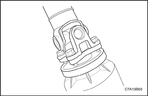
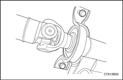
- Remove the bolts securing the propeller shaft yoke flange to the rear drive module flange.

- Index mark the relationship of the propeller shaft to the power take-off unit (PTU) flange.
- Place a support under the propeller shaft at the PTU.
- Remove the bolts securing the propeller shaft to the PTU flange.
- Place a support under the propeller shaft at the support bearing.
- Remove the bolts securing the propeller shaft support bearing to the vehicle underbody.
- While supporting the propeller shaft, move the propeller shaft rearward to disengage the constant velocity joint from the PTU flange.
- Remove the propeller shaft from the vehicle.
Installation Procedure
- While supporting the front, center, and rear of the propeller shaft, install the propeller shaft to the vehicle.
- Thoroughly clean the center bearing to vehicle mounting bolts and apply thread locker, Saturn P/N 21005994 (Canadian P/N 10953488), to the bolt threads.
- Install, but do not tighten, the support bearing mounting bolts.
- Pull the forward section of the propeller shaft rearward and install the propeller shaft to the PTU flange.
- Align the index marks on the propeller shaft constant velocity joint and the PTU flange.
- Thoroughly clean the propeller shaft flange mounting bolts and apply thread locker, Saturn P/N 21005994 (Canadian P/N 10953488), to the bolt threads.
- Install the front propeller shaft mounting bolts.
Tighten
Tighten the bolts to 25 N•m (19 lb-ft).
- Align the index marks on the propeller shaft yoke flange and the rear drive module flange and install the propeller.
- Thoroughly clean the yoke mounting bolts and apply thread locker, Saturn P/N 21005994(Canadian P/N 10953488), to the bolt threads.
- Install the bolts to the propeller shaft yoke and rear drive module flange.
Tighten
Tighten the bolts to 50 N•m (37 lb-ft).
- Tighten the support bearing mounting bolts.
Tighten
Tighten the bolts to 25 N•m (19 lb-ft).
- Remove the support stands from the propeller shaft.
- Lower the vehicle.

Wheel Drive Shaft - Rear
Removal Procedure
- Raise and suitably support the vehicle.
- Remove the rear wheel drive shaft spindle nut.
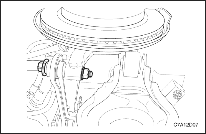
- Remove the trailing arm bracket to underbody bolts. Refer to Section 2D, Rear Suspension.

- Remove the toe link to knuckle nut and bolt.
- Remove the lower control arm to knuckle bolt and nut.

- Loose the knuckle to upper control arm nut and bolt. Do not remove the nut and bolt.
Important : Support the wheel drive shaft while it is disengaged from the wheel hub and bearing assembly in order to avoid damaging the wheel drive shaft seals.
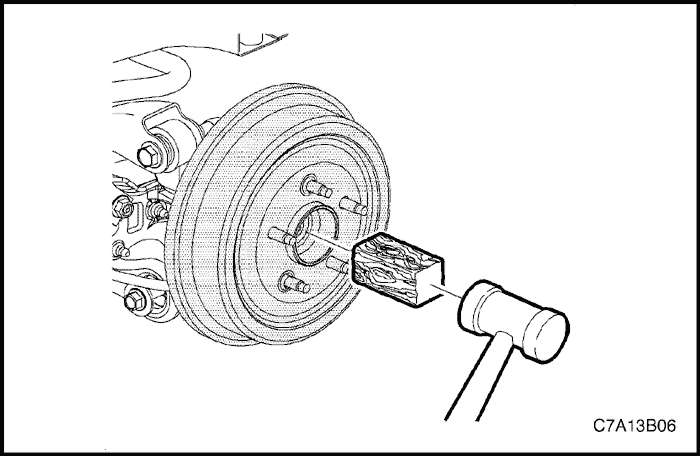
- Place a block of wood against the wheel drive shaft spindle and tap with a hammer to release the spindle from the wheel hub and bearing assembly.
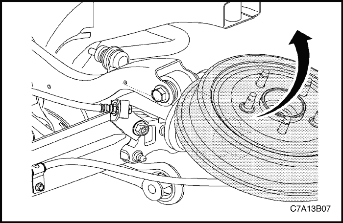
- Rotate the suspension knuckle upward and secure with heavy mechanics wire, or equivalent.
- Remove the wheel drive shaft from the rear drive module(RDM).
Installation Procedure
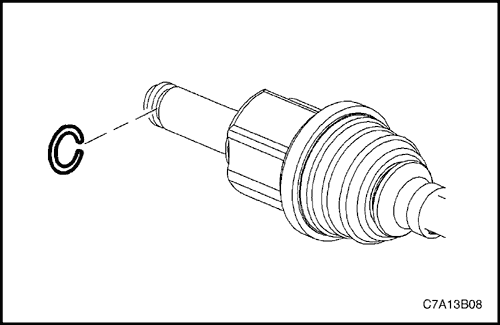
- Install a new wheel drive shaft retaining ring to the inner tripot joint.
- Install the wheel drive shaft to the output shaft of the rear drive module(RDM). Ensure that the tripot joint is fully seated on the output shaft by grasping the tripot joint and attempting to pull free of the output shaft.

- Rotate the suspension knuckle downward while simultaneously guiding the constant velocity (CV) joint spindle to the wheel hub and bearing assembly of the suspension knuckle.
- Hand install a new wheel drive shaft spindle nut.
- Install the lower control arm to knuckle bolt and nut.
Tighten
Tighten the lower control arm to knuckle bolt and nut to 160 N•m (118 lb-ft).
- Install the trailing arm bracket to underbody bolts.
Tighten
Tighten the trailing arm bracket to underbody bolts to 110 N•m (81 lb-ft).
- Install the toe link to knuckle nut and bolt.
Tighten
- Tighten the toe link to knuckle nut and bolt to 160 N•m (118 lb-ft).
- Tighten the knuckle to upper control arm nut and bolt to 160 N•m (118 lb-ft).
- Check the rear wheel alignment. Refer to Section 2B, Wheel Alignment.
Rear Drive Module
Removal Procedure
- Ignition key OFF.
- Remove the propeller shaft and wheel drive axles from the rear drive module. Refer to Propeller Shaft and Wheel Drive Axles in this section.
- Remove the exhaust muffler. Refer to Section 1G3, Engine Exhaust-HFV6 3.2L.
- Remove the spare tire securing bracket bolt.
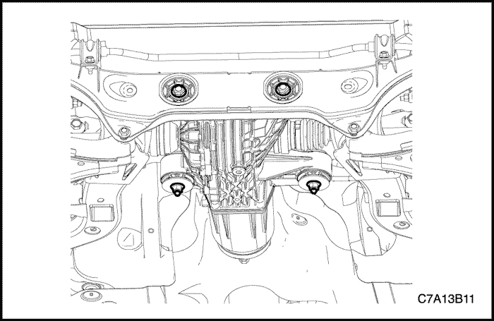
- Remove the front/rear securing bolts of the rear drive module.
Important : Support rear drive module while it is disengaged from the body panel.
- Lower the support slowly with care in order to avoid damaging the control module wiring harness.
- Remove the coupling control module(CCM) connector.
- Remove the rear drive module from the vehicle.
Installation Procedure
- Raise the rear drive module onto the support slowly and connect the coupling control module(CCM) connector.
- Install the front/rear securing bolts of the rear drive module.
Tighten
- Tighten the front securing bolts of the rear drive module to 117 N•m (86 lb-ft).
- Tighten the rear securing bolts of the rear drive module to 180 N•m (133 lb-ft).
- Install the propeller shaft and wheel drive axles to the rear drive module flange. Refer to Propeller Shaft and Wheel Drive Axles in this section.
- Install the exhaust muffler. Refer to Section 1G3, Engine Exhaust-HFV6 3.2L.
- Install the spare tire and secure the bracket bolt.
- Check the rear wheel aligment. Refer to Section 2B, Wheel Alignmetn.
UNIT REPAIR
Wheel Drive Shaft - Rear
Tools Required
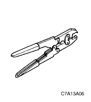
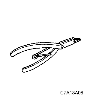
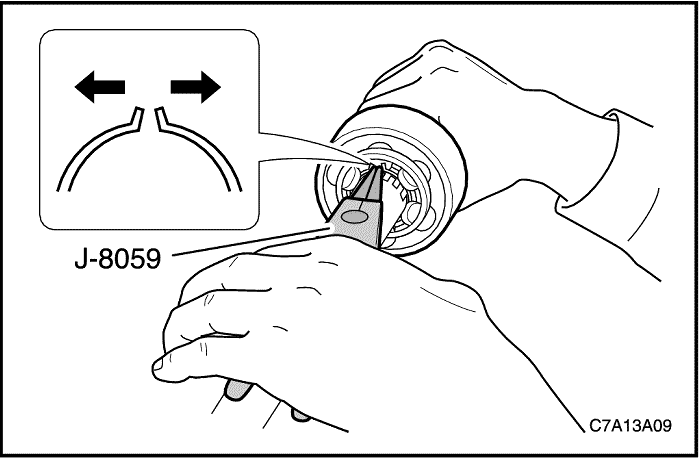
J–8059 Snap Ring Pliers
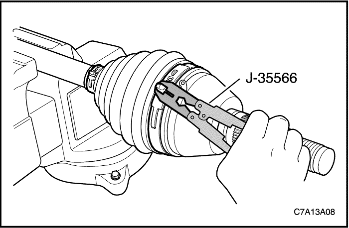
J–35566 Seal Clamp Pliers
Disassembly Procedure
- Remove the wheel drive shaft from the vehicle. Refer to ” Wheel Drive Shaft – Rear” in this section.
- Remove the large seal retaining clamp. Discard the clamp.
- Remove the small seal retaining clamp. Discard the clamp.
- Degrease the joint.
- Spread the snap ring using the snap ring pliers J–8059 and remove the outer joint from the drive shaft.
Caution : Do not disassemble the outer joint assembly. Parts are match fit and cannot be serviced separately. Improper reassembly will adversely affect both performance and safety.
- Remove the seal from the joint assembly.
Assembly Procedure
- Install the seal onto the drive shaft.
- Spread the snap ring using the snap ring pliers J–8059 and install the outer joint onto the drive shaft.
- Fill the joint seal with 170 to 190 g (6.0 to 6.7ounces) of the recommended grease. Repack the joint with 170 to 190 g (6.0 to 6.7 ounces) of the recommended grease.
- Install a new large seal retaining clamp and a new small seal retaining clamp.
- Crimp the new small seal retaining clamp and the new large seal retaining clamp using the seal clamp pliers J–35566.
- Install the drive shaft to the vehicle. Refer to “Wheel Drive Shaft - Rear” in this section.
Rear Drive Module
Disassembly Procedure
- Place a drain pan below the rear drive module.
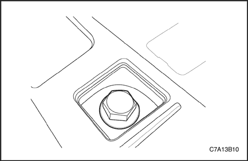
- Remove the drain plug from the bottom of the rear drive module and remove the fill plug from the left side of the rear drive module.
- Drain the fluid.
- Remove the differential carrier assembly side bracket.
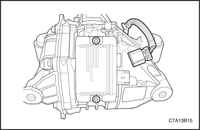
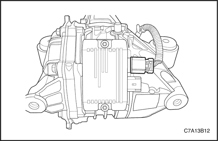
- Disconnect the coupling control module connector and remove the coupling control module from the rear drive module housing.
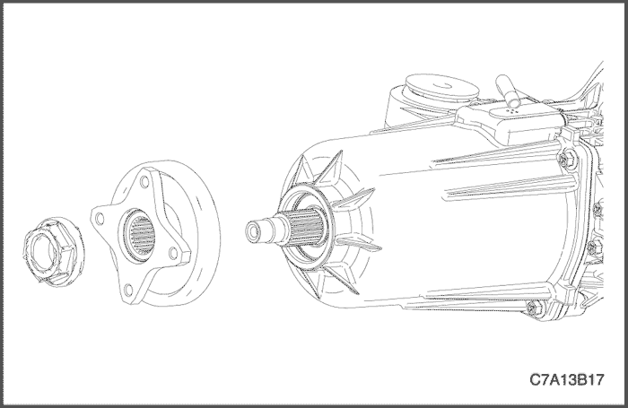
- Remove and discard the pinion flange nut.
- Remove the pinion flange.
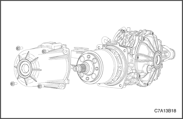
- Remove the clutch coupling assembly, housing and seal.
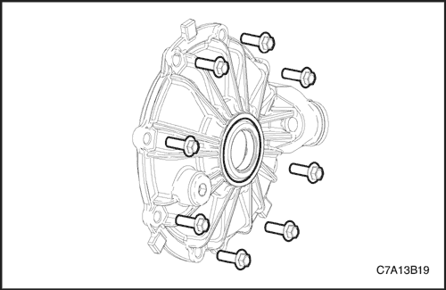
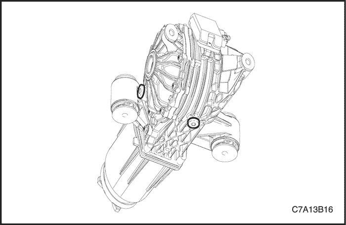
- Remove the differential carrier assembly side cover and seal.
- Remove the rear wheel drive shaft seals.
Assembly Procedure
Tools Required
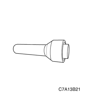
DT-48254 Rear Wheel Drive Shaft Seal Installer.
- Install the differential carrier assembly side cover and seal.
Tighten
Tighten the differential carrier assembly side bracket securing bolts to 29 N•m (21 lb-ft).
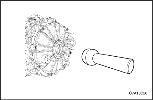
- Install the rear wheel drive shaft seal using the rear wheel drive shaft seal Installer DT-48254.
- Install the clutch coupling assembly, housing and seal.
Tighten
Tighten the clutch coupling assembly housing securing bolt to 26 N•m (19 lb-ft).
- Install the pinion flange.
- Install the new pinion flange nut.
Tighten
Tighten the pinion flange nut to 203 N•m (150 lb-ft).
- Install the coupling control module onto the rear drive module housing and connect the coupling control module connector.
Tighten
Tighten the coupling control module securing bolt to 10 N•m (71 lb-ft).
- Install the differential carrier assembly side bracket.
Tighten
Tighten the differential carrier assembly side bracket bolt to 29 N•m (21 lb-ft).
- Thoroughly clean the drain plug threads and apply thread sealer, GM P/N 12346004 (Canadian P/N 10953480), to the plug threads.
Tighten
Tighten the plug to 42 N•m (31 lb-ft).
- Fill the RDM with lubricant until the lubricant overflows through the fill plug hole.
- Thoroughly clean the fill plug threads and apply thread sealer, GM P/N 12346004 (Canadian P/N 10953480), to the plug threads.
- Install the fill plug.
Tighten
Tighten the plug to 42 N•m (31 lb-ft).
GENERAL DESCRIPTION AND SYSTEM OPERATION
Wheel Drive Shaft
Wheel Drive Shafts are flexible shaft assemblies that transmit rotational force from the differential carrier assembly to the rear–wheel assemblies.
Each axle assembly consists of an inner and an outer constant–velocity joint connected to an wheel drive shaft. The inner and outer joint are completely flexible, but it cannot move in and out.
Propeller Shaft
The propeller shaft assembly is a 2-piece design. The front shaft consists of a plunging A-type constant velocity joint at the front and a universal joint and yoke at the rear.
The rear shaft consists of a center bearing and a center yoke, which are pressed onto the rear half of the propshaft and retained by a snap ring. The front and rear shafts are joined together at the yokes with a universal joint. The rear shaft attaches to the axle with a flange which is attached to the rear shaft with a universal joint.
The center bearing provides support where the front and rear shafts mate and is bolted to the underbody. The front constant velocity joint is bolted to the power take-off unit (PTU), and the rear universal joint flange is bolted to the clutch coupling assembly.
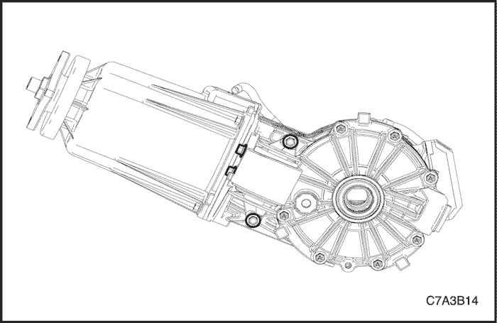
Rear Drive Module
The rear drive module (RDM) in this vehicle consists of a coupling control module and an aluminum housing which contains a clutch coupling assembly and a differential.
The on-demand rear differential distributes variable torque/power to the rear wheels via individual axle shafts.
The on-demand system operates as follows: only when front wheel slippage is encountered torque/power is proportioned to the rear wheels. As long as there is no front-to-rear speed difference; there is no torque/power to the rear wheels.
When front-to-rear wheel slippage does occur, the coupling control module receive the information from the ECM, BCM, EBCM and the coupling control module sends a signal to the clutch coupling assembly to actuate the clutch coupling pack which then distributes torque/power to the rear wheels. Rear axle ouput torque is controlled from 0Nm ~ 2,530Nm depending on various road condition such as asphalt, sand, snow and ice. The torque distribution ratio of front/rear axle is controlled continuously to have optimized value between 100/0 ~ 50/50 in real time depend on vehicle driving status & road condition.
The system has an integral protection device that reduces rear wheel torque when excessive heat is generated, thus protecting the rear wheel drive module (RDM).
Rear Differential Assembly Fluid
The rear differential assembly uses a specifically developed synthetic hypoid fluid which is intended for a lifetime service interval. However, proper fluid level must be maintained to ensure proper rear differential assembly operation.