Captiva |
||||||||
|
||||||||
|
Application
|
Description
|
Unit
|
HFV6 3.2L
|
||
|
General Data
|
Engine Type
|
-
|
V6
|
||
|
Bank Angle
|
°
|
60°
|
|||
|
Displacement
|
cm³
|
3,195
|
|||
|
Bore × Stroke
|
mm (in.)
|
89 × 85.6 (3.50 × 3.37)
|
|||
|
Compression Ratio
|
-
|
10.3 : 1
|
|||
|
Firing Order
|
-
|
1-2-3-4-5-6
|
|||
|
Maximum Power
|
hp (kw)
|
226.6 hp (169 kw) @ 6,600 rpm
|
|||
|
Maximum Torque
|
lb-ft (N·m)
|
219.1 lb-ft (297 N•m) @ 3,200 rpm
|
|||
|
Cylinder Block
|
Cylinder Bore Diameter
|
mm (in.)
|
88.992 - 89.008 (3.503 - 3.504)
|
||
|
Cylinder Out of Round(MAX)
|
mm (in.)
|
0.013 (0.000512)
|
|||
|
Crankshaft Main Bearing Bore Diameter
|
mm (in.)
|
72.867 - 72.881 (2.8688 - 2.8693)
|
|||
|
Cylinder Head Deck Surface Flatness
|
mm (in.)
|
0.05 (0.00197)
|
|||
|
Crankshaft
|
Connecting Rod Journal Diameter
|
mm (in.)
|
55.992 - 56.008 (2.2044 - 2.2050)
|
||
|
Connecting Rod journal Out of Round
|
mm (in.)
|
0.005 (0.00020)
|
|||
|
Connecting Rod Journal Taper
|
mm (in.)
|
0.005 (0.00020)
|
|||
|
Connecting Rod Journal Width (Production)
|
mm (in.)
|
22.000 (0.8661)
|
|||
|
Connecting Rod Journal Width (Service Limit)
|
mm (in.)
|
21.920 - 22.080 (0.8630 - 0.8693)
|
|||
|
Crankshaft End Play
|
mm (in.)
|
0.100 - 0.330 (0.00394 - 0.0130)
|
|||
|
Crankshaft Main Bearing Clearance
|
mm (in.)
|
0.010 - 0.060 (0.00039 - 0.00236)
|
|||
|
Crankshaft Main Journal Diameter
|
mm (in.)
|
67.992 - 68.008 (2.6768 - 2.6775)
|
|||
|
Crankshaft Main Journal Out of Round
|
mm (in.)
|
0.005 (0.00020)
|
|||
|
Crankshaft Main Journal Taper
|
mm (in.)
|
0.005 (0.00020)
|
|||
|
Crankshaft Main Journal Width #2, 4 (Production)
|
mm (in.)
|
24 (0.9449)
|
|||
|
Crankshaft Main Journal Width #2, 4 (Service)
|
mm (in.)
|
23.900 - 24.100 (0.9409 - 0.9488)
|
|||
|
Crankshaft Main Journal Width #3 (Production)
|
mm (in.)
|
24.4 (0.9606)
|
|||
|
Crankshaft Main Journal Width #3 (Service)
|
mm (in.)
|
24.360 - 24.440 (0.9590 - 0.9622)
|
|||
|
Crankshaft Main Journal Thrust Wall Runout
|
mm (in.)
|
0.000 - 0.040 (0.0000 - 0.00157)
|
|||
|
Crankshaft Main Journal Thrust Wall Square
|
mm (in.)
|
0.000 - 0.010 (0.0000 - 0.00039)
|
|||
|
Crankshaft Rear Flange Runout
|
mm (in.)
|
0.025 (0.00098)
|
|||
|
Crankshaft Reluctor Ring Runout (MAX)
|
mm (in.)
|
1.500 (0.0590)
|
|||
|
Crankshaft Thrust Bearing Clearance
|
mm (in.)
|
0.076 - 0.305 (0.0030 - 0.0120)
|
|||
|
Crankshaft Thrust Surface Runout
|
mm (in.)
|
0.04 (0.00157)
|
|||
|
Crankshaft Thrust Surface - Height Diameter
|
mm (in.)
|
95.000 (3.7401)
|
|||
|
Connecting Rod
|
Connecting Rod Length - Bore Center-to-Center
|
mm (in.)
|
155.800 (6.1338)
|
||
|
Connecting Rod Bore Diameter - Bearing End
|
mm (in.)
|
59.620 - 59.636 (2.3472 - 2.3479)
|
|||
|
Connecting Rod Bore Diameter - Pin End
|
mm (in.)
|
24.007 - 24.021 (0.9452 - 0.9457)
|
|||
|
Connecting Rod Width - Pin End
|
mm (in.)
|
26.000 (1.0236)
|
|||
|
Connecting Rod Width - Bearing End
|
mm (in.)
|
21.775 (0.8573)
|
|||
|
Connecting Rod Side Clearance
|
mm (in.)
|
0.095 - 0.355 (0.0037 - 0.0140)
|
|||
|
Connecting Rod Bearing Clearance
|
mm (in.)
|
0.010 - 0.070 (0.00039 - 0.0028)
|
|||
|
PISTON
|
Piston Diameter Center-to-Center
|
mm (in.)
|
88.956 - 88.974 (3.5022 - 3.5029)
|
||
|
Piston Pin Bore Diameter
|
mm (in.)
|
24.004 - 24.009 (0.9450 - 0.9452)
|
|||
|
Piston Ring Groove Width - First (Top) Compression Ring
|
mm (in.)
|
1.220 - 1.240 (0.0480 - 0.0488)
|
|||
|
Piston Ring Groove Width - Second Compression Ring
|
mm (in.)
|
1.510 - 1.530 (0.0594 - 0.0602)
|
|||
|
Piston Ring Groove Width - Oil Control Ring
|
mm (in.)
|
2.510 - 2.530 (0.0988 - 0.0996)
|
|||
|
Piston to Bore Clearance
|
mm (in.)
|
0.018 - 0.052 (0.00071 - 0.00205)
|
|||
|
PISTON PIN
|
Piston Pin Diameter
|
mm (in.)
|
23.997 - 24.000 (0.94476 - 0.94488)
|
||
|
Piston Pin Length
|
mm (in.)
|
60.600 - 61.100 (2.3858 - 2.4055)
|
|||
|
Piston Pin Clearance to Connecting Rod Bore
|
mm (in.)
|
0.007 - 0.024 (0.00028 - 0.00094)
|
|||
|
Piston Pin Clearance to Piston Pin Bore
|
mm (in.)
|
0.004 - 0.012 (0.00016 - 0.00047)
|
|||
|
PISTON RINGS
|
Piston Ring to Groove Clearance
|
First Compression Ring
|
mm (in.)
|
0.030 - 0.065 (0.0012 - 0.0026)
|
|
|
.
|
Second Compression Ring
|
mm (in.)
|
0.015 - 0.060 (0.00059 - 0.00236)
|
||
|
.
|
Oil Control Ring
|
mm (in.)
|
0.030 - 0.170 (0.0012 - 0.0067)
|
||
|
Piston Ring End Gap
|
First Compression Ring
|
mm (in.)
|
0.150 - 0.300 (0.0059 - 0.0118)
|
||
|
.
|
Second Compression Ring
|
mm (in.)
|
0.300 - 0.500 (0.0118 - 0.0197)
|
||
|
.
|
Oil Control Ring
|
mm (in.)
|
0.250 - 0.750 (0.0098 - 0.0295)
|
||
|
CYLINDER HEAD
|
Combustion Chamber Volume
|
cc
|
49.400
|
||
|
Valve Guide Bore Diameter - Intake
|
mm (in.)
|
6.000 - 6.020 (0.2362 - 0.2370)
|
|||
|
Valve Guide Bore Diameter - Exhaust
|
mm (in.)
|
6.000 - 6.020 (0.2362 - 0.2370)
|
|||
|
Valve Guide Installed Height
|
mm (in.)
|
14.050 - 14.550 (0.5531 - 0.5728)
|
|||
|
Stationary Hydraulic Lash Adjuster (SHLA) Bore Diameter
|
mm (in.)
|
12.008 - 12.030 (0.4727 - 0.4736)
|
|||
|
Valve Seat Angle - Seating Surface
|
°
|
45°
|
|||
|
Valve Seat Angle - Relief Surface
|
°
|
30°
|
|||
|
Valve Seat Angle - Undercut Surface
|
°
|
60°
|
|||
|
Valve Seat Runout
|
mm (in.)
|
0.050 (0.00197)
|
|||
|
Valve Seat Width - Exhaust Seating Surface
|
mm (in.)
|
1.400 - 1.800 (0.0551 - 0.0709)
|
|||
|
Valve Seat Width - Exhaust Relief Surface
|
mm (in.)
|
0.700 - 0.900 (0.0276 - 0.0354)
|
|||
|
Valve Seat Width - Intake Seating Surface
|
mm (in.)
|
1.000 - 1.400 (0.0374 - 0.0551)
|
|||
|
Valve Seat Width - Intake Relief Surface
|
mm (in.)
|
0.500 - 0.700 (0.0197 - 0.0276)
|
|||
|
Engine Block Deck Surface Flatness
|
mm (in.)
|
0.05 (0.0197)
|
|||
|
Exhaust Manifold Deck Surface Flatness
|
mm (in.)
|
0.25 (0.0098)
|
|||
|
Intake Manifold Deck Surface Flatness
|
mm (in.)
|
0.05 (0.0197)
|
|||
|
VALVE SYSTEM
|
Face Angle
|
°
|
44.25°
|
||
|
Face Runout
|
mm (in.)
|
0.038 (0.0015)
|
|||
|
Valve Face Width
|
Intake
|
mm (in.)
|
2.180 (0.0858)
|
||
|
.
|
Exhaust
|
mm (in.)
|
2.750 (0.1083)
|
||
|
Valve Head Diameter
|
Intake
|
mm (in.)
|
35.030 - 35.290 (1.3791 - 1.3894)
|
||
|
.
|
Exhaust
|
mm (in.)
|
30.470 - 30.730 (1.1996 - 1.2098)
|
||
|
Valve Length
|
Intake
|
mm (in.)
|
101.230 (3.9854)
|
||
|
.
|
Exhaust
|
mm (in.)
|
97.110 (3.8232)
|
||
|
Valve Stem Diameter
|
Standard
|
mm (in.)
|
5.955 - 5.975 (0.2344 - 0.2352)
|
||
|
.
|
Oversize
|
mm (in.)
|
6.013 - 6.033 (0.2367 - 0.2375)
|
||
|
Valve Stem to Guide Clearance
|
mm (in.)
|
0.025 - 0.065 (0.00098 - 0.00256)
|
|||
|
Hydraulic Lash Adjuster Diameter
|
mm (in.)
|
11.986 - 12.000 (0.47189 - 0.47244)
|
|||
|
Hydraulic Lash Adjuster to Bore Clearance
|
mm (in.)
|
0.037 - 0.041 (0.00146 - 0.00161)
|
|||
|
Rocker Arm/Camshaft Follower Ratio
|
-
|
1.68 : 1
|
|||
|
Rocker Arm/Camshaft Follower Roller Diameter
|
-
|
17.740 - 17.800 (0.6984 - 0.7008)
|
|||
|
Valve Spring Free Length
|
mm (in.)
|
42.500 - 45.500 (1.6732 - 1.7913)
|
|||
|
Valve Spring Installed Height - Closed
|
mm (in.)
|
35.000 (1.3779)
|
|||
|
Valve Spring Installed Height - Open
|
mm (in.)
|
24.000 (0.9449)
|
|||
|
Valve Spring Load - Closed
|
N
|
247 - 273 N
|
|||
|
Valve Spring Load - Open
|
N
|
598 - 662 N
|
|||
|
Valve Spring Diameter - Inside Top
|
mm (in.)
|
12.200 - 12.700 (0.4803 - 0.50)
|
|||
|
Valve Spring Diameter - Outside Top
|
mm (in.)
|
18.000 - 20.500 (0.7087 - 0.8071)
|
|||
|
Valve Spring Diameter - Inside Bottom
|
mm (in.)
|
17.950 - 18.450 (0.7067 - 0.7264)
|
|||
|
Valve Spring Diameter - Outside Bottom
|
mm (in.)
|
26.000 (1.0236)
|
|||
|
Valve Spring Coil Thickness
|
mm (in.)
|
3.250 - 3.900 (0.1279 - 0.1535)
|
|||
|
Valve Spring Total Number of Coils
|
-
|
7.1
|
|||
|
CAMSHAFT
|
Camshaft Bearing Inside Diameter - Front No. 1
|
mm (in.)
|
35.000 - 35.020 (1.3779 - 1.3787)
|
||
|
Camshaft Bearing Inside Diameter - Middle & Rear No. 2 - 4
|
mm (in.)
|
27.000 - 27.020 (1.0630 - 1.0638)
|
|||
|
Camshaft End Play
|
mm (in.)
|
0.045 - 0.215 (0.0018 - 0.00846)
|
|||
|
Camshaft Journal Diameter - Front No. 1
|
mm (in.)
|
34.936 - 34.960 (1.3754 - 1.3764)
|
|||
|
Camshaft Journal Diameter - Middle & Rear No. 2 - 4
|
mm (in.)
|
26.936 - 26.960 (1.0605 - 1.0614)
|
|||
|
Camshaft Journal Out of Round
|
mm (in.)
|
0.006 (0.00024)
|
|||
|
Camshaft Journal to Bore Clearance
|
mm (in.)
|
0.040 - 0.084 (0.0016 - 0.0033)
|
|||
|
Camshaft Runout - Front & Rear No. 1 & 4
|
mm (in.)
|
0.025 (0.00098)
|
|||
|
Camshaft Runout - Front & Rear No. 2 & 3
|
mm (in.)
|
0.050 (0.00197)
|
|||
|
Camshaft Lobe Duration - Exhaust (@ 0.150 mm Lift)
|
°
|
238°
|
|||
|
Camshaft Lobe Duration - Intake (@ 0.150 mm Lift)
|
°
|
237°
|
|||
|
Camshaft Lobe Height - Exhaust
|
mm (in.)
|
6.6 (0.2598)
|
|||
|
Camshaft Lobe Height - Intake
|
mm (in.)
|
6.5 (0.2559)
|
|||
|
Camshaft Lobe Overlap (@ 0.150 Lift)
|
°
|
- 5° (no overlap)
|
|||
|
Valve Opens - Exhaust
|
°
|
229° BTDC
|
|||
|
Valve Opens - Intake
|
°
|
14° ATDC
|
|||
|
Center-line - Exhaust
|
°
|
111° BTDC
|
|||
|
Center-line - Intake
|
°
|
132° ATDC
|
|||
|
Valve Colses - Exhaust
|
°
|
9° ATDC
|
|||
|
Valve Closes - Intake
|
°
|
252° ATDC
|
|||
|
Valve Lift - Exhaust
|
mm (in.)
|
10.8 (0.4252)
|
|||
|
Valve Lift - Intake
|
mm (in.)
|
10.8 (0.4252)
|
|||
|
OIL PUMP
|
Type
|
-
|
Gerotor
|
||
|
Gear Diameter - Outer
|
mm (in.)
|
87.095 - 87.175 (3.4289 - 3.4321)
|
|||
|
Gear Bore Depth
|
mm (in.)
|
15.565 - 15.600 (0.6128 - 0.6142)
|
|||
|
Gear Bore Diameter
|
mm (in.)
|
87.275 - 87.325 (3.4360 - 3.4380)
|
|||
|
Gear Thickness
|
mm (in.)
|
15.511 - 15.536 (0.6107 - 0.6116)
|
|||
|
Gear to Cover Clearance
|
mm (in.)
|
0.030 - 0.085 (0.0012 - 0.0033)
|
|||
|
Gear to Housing Clearance
|
mm (in.)
|
0.100 - 0.230 (0.0039 - 0.0090)
|
|||
|
Inner Gear Tip Clearance
|
mm (in.)
|
0.075 - 0.180 (0.0029 - 0.0071)
|
|||
|
Crankshaft Clearance to Housing
|
mm (in.)
|
0.040 - 0.130 (0.0016 - 0.0051)
|
|||
|
Inner Gerotor Hub Diameter
|
mm (in.)
|
53.310 - 53.335 (2.0988 - 2.0998)
|
|||
|
Housing Hub Diameter
|
mm (in.)
|
53.380 - 53.420 (2.1016 - 2.1031)
|
|||
|
Inner Gerotor Hub Clearance to Housing
|
mm (in.)
|
0.045 - 0.110 (0.0018 - 0.0043)
|
|||
|
Lubricating System
|
Oil Type
|
-
|
API SJ (ACEA A1) grade SAE 0W-30
|
||
|
Oil Capacity - with Filter
|
L
|
7.4
|
|||
|
Oil Capacity - without Filter
|
L
|
7.0
|
|||
|
Oil Pressure - Minimum at Idle
|
kPa
|
69
|
|||
|
Oil Pressure - Minimum at 2,000 rpm
|
kPa
|
138
|
|||
|
Piston Cooling Jet Valve Opening System
|
kPa
|
170 - 230
|
|||
|
Application
|
N•m
|
Lb-Ft
|
Lb-In
|
|
Accessory Drive Belt Idler Pulley Attaching Bolt
|
50
|
37
|
-
|
|
Accessory Drive Belt Tensioner Attaching Bolts
|
50
|
37
|
-
|
|
Air Cleaner Element Cover Screws
|
2
|
-
|
18
|
|
Air Cleaner Housing Bolts
|
6
|
-
|
53
|
|
Battery Hold-Down Bar Bracket Retaining Nuts
|
10
|
-
|
89
|
|
Battery Tray Retaining Bolts
|
10
|
-
|
89
|
|
Camshaft Bearing Cap Bolts
|
10
|
-
|
89
|
|
Camshaft Intermediate Driveshaft Sprocket Attaching Bolt
|
65
|
48
|
-
|
|
Camshaft Position Actuator Attaching Bolt
|
58
|
43
|
-
|
|
Connecting Rod Cap Bearing Bolts
|
35, Loosen all, 25 +110°
|
22, Loosen all, 18 +110°
|
-
|
|
Coolant Drain Threaded Plug
|
31
|
23
|
-
|
|
Cradle Mounting Bolts
|
155
|
114
|
-
|
|
Cradle Support Bracket Mounting Bolts
|
50
|
37
|
-
|
|
Crankshaft Main Bearing Cap Inboard Attaching Bolt
|
20 +80°
|
15 +80°
|
-
|
|
Crankshaft Main Bearing Cap Outboard Attaching Bolt
|
15 +110°
|
11 +110°
|
-
|
|
Crankshaft Main Bearing Cap Side Attaching Bolt
|
30 +60°
|
22 +60°
|
-
|
|
Crankshaft Oil Deflector Attaching Bolt
|
10
|
-
|
89
|
|
Crankshaft Pulley Bolts
|
100 +150°
|
74 +150°
|
-
|
|
Crankshaft Rear Oil Seal Housing Attaching Bolt
|
10
|
-
|
89
|
|
Cylinder Block Rear Oil Gallery Threaded Plug
|
31
|
23
|
-
|
|
Cylinder Head Bolts (M11)
|
45 +120°
|
33 +120°
|
-
|
|
Cylinder Head Bolts (M8)
|
15 +60°
|
11 +60°
|
-
|
|
Cylinder Head Cover Bolts
|
10
|
-
|
89
|
|
Engine Dress Cover Bolts and Nuts
|
8
|
-
|
71
|
|
Engine Fuse Block Lower Cover Bolts
|
10
|
-
|
89
|
|
Engine Fuse Block Retaining Bolts
|
3
|
-
|
27
|
|
Engine Lift Bracket Attaching Bolt
|
50
|
37
|
-
|
|
Engine Mount Adapter Bolts
|
50
|
37
|
-
|
|
Engine Mount Support Bracket Upper Bolts
|
90
|
66
|
-
|
|
Engine Mount Support Bracket Lower Bolt
|
50
|
37
|
-
|
|
Engine Mount Frame Side Bracket Bolt
|
100
|
74
|
-
|
|
Engine Mount Frame Side Bracket Nuts
|
90
|
66
|
-
|
|
Fuel Rail Assembly Retaining Bolts
|
25
|
18
|
-
|
|
Engine Mount Frame Side Bracket Nuts
|
90
|
66
|
-
|
|
Evaporative Emission Canister Purge Solenoid Bracket Bolt
|
5
|
-
|
44
|
|
Exhaust Camshaft Gear Bolt
|
50 + 60° +15°
|
37 + 60° +15°
|
-
|
|
Exhaust Front Pipe Mounting Bracket Bolt and Nut
|
40
|
30
|
-
|
|
Exhaust Manifold Heat Shield Bolts
|
10
|
-
|
89
|
|
Exhaust Manifold to Cylinder Head Attaching Bolts
|
20
|
15
|
-
|
|
Flexible Plate Bolts
|
65
|
48
|
-
|
|
Engine Front Cover Assembly Bolts
|
23
|
17
|
-
|
|
Fuel Injector Wiring Harness Bracket Attaching Bolt
|
20
|
15
|
-
|
|
Fuel Rail Assembly Retaining Bolts
|
10
|
-
|
89
|
|
Lower Intake Manifold to Cylinder Head Attaching Bolt
|
23
|
17
|
-
|
|
Oil Filter Adapter Retaining Bolts
|
8
|
-
|
71
|
|
Oil Gallery Threaded Plug
|
31
|
23
|
-
|
|
Oil Jet Attaching Bolt
|
10
|
-
|
89
|
|
Oil Level Sensor
|
20
|
15
|
-
|
|
Oil Level Stick Gauge Tube Attaching Bolt
|
10
|
-
|
89
|
|
Oil Pan Drain Plug
|
25
|
18
|
-
|
|
Oil Pan Flange-to-Transaxle Retaining Bolts
|
50
|
37
|
-
|
|
Oil Pan to Crankshaft Rear Oil Seal Housing Attaching Bolt
|
10
|
-
|
89
|
|
Oil Pan to Cylinder Block Attaching Bolt
|
23
|
17
|
-
|
|
Oil Pressure Sensor
|
13
|
-
|
115
|
|
Oil Pump Retaining Bolts
|
23
|
17
|
-
|
|
Oil Suction Pipe Retaining Bolts
|
10
|
-
|
89
|
|
Primary Timing Chain Upper Guide Attaching Bolt
|
23
|
17
|
-
|
|
Primary Timing Chain Tensioner Attaching Bolt
|
23
|
17
|
-
|
|
Pup Converter-to-Exhaust Front Pipe Retaining Nuts
|
40
|
30
|
-
|
|
Rear Timing Belt Cover Bolts
|
7
|
-
|
62
|
|
Secondary Timing Chain Guide Attaching Bolt
|
23
|
17
|
-
|
|
Secondary Timing Chain Shoe Attaching Bolt
|
23
|
17
|
-
|
|
Secondary Timing Chain Tensioner Attaching Bolt
|
23
|
17
|
-
|
|
Spark Plugs
|
18
|
13
|
-
|
|
Timing Belt Automatic Tensioner Bolt
|
25
|
18
|
-
|
|
Timing Belt Idler Pulley Bolt & Nut
|
25
|
18
|
-
|
|
Transaxle Front Mount Retaining Bolts
|
50
|
37
|
-
|
|
Transaxle Front Mount-to-Transaxle Through Bolt & Nut
|
90
|
66
|
-
|
|
Transaxle Mount Assembly Retaining Bolts
|
37
|
27
|
-
|
|
Transaxle Mount Bracket Retaining Bolts
|
50
|
37
|
-
|
|
Transaxle Rear Mount Retaining Bolts
|
90
|
66
|
-
|
|
Transaxle Rear Mount Bracket Retaining Bolts
|
90
|
66
|
-
|
|
Transaxle Rear Mount-to-Bracket Through Bolt & Nut
|
90
|
66
|
-
|
|
Transaxle-to-Oil Pan Flange Bolt
|
50
|
37
|
-
|
|
Transaxle Torque Coverter Bolts
|
45
|
33
|
-
|
|
Upper Intake Manifold to Lower Intake Manifold Attaching Bolt
|
23
|
17
|
-
|
|
Upper Intake Manifold to Cylinder Head Attaching Bolt
|
23
|
17
|
-
|
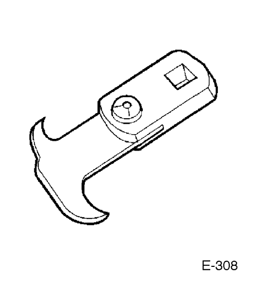 |
E308
Seal Remover
|
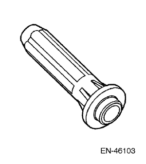 |
EN-46103
Camshaft Actuator Valve Seal Installer
|
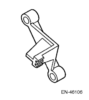 |
EN-46106
Flexplate Holding Tool
|
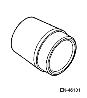 |
EN-46101
Spark Plug Tube Seal Guide Set
|
 |
EN-46105-1&2
Camshaft Locking Tool Set
|
 |
EN-46108
Timing Chain Retention Tool Set
|
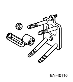 |
EN-46110
On-Vehicle Valve Spring Compressor
|
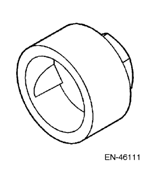 |
EN-46111
Crankshaft Rotation Socket
|
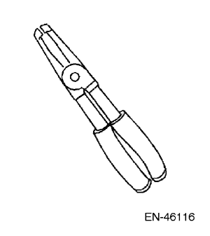 |
EN-46116
Valve Stem Seal Remover/Installer
|
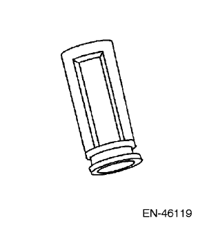 |
EN-46119
Off-Vehicle Valve Spring Compressor Adaptor
|
 |
EN-46121
Connecting Rod Guide Pin Set
|
 |
Timing Chain Tensioner Retraction Springs
|
 |
EN-46120 & J-42096
Valve Guide Reamer
|
 |
EN-46122
Oil Control Valve Check Ball Remover/Installer
|
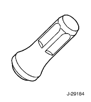 |
J-29184
Crankshaft Front Oil Seal Installer
|
 |
J-41816
Three Legged Puller
|
 |
J-41998-B
Crankshaft Pulley Installer
|
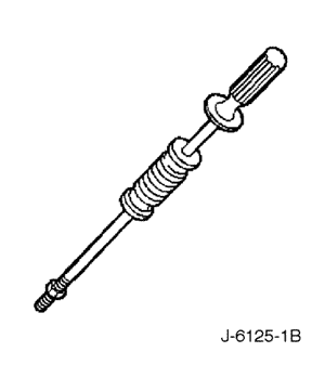 |
J-6125-1B
Slide Hammer
|
 |
J-36648-A
Oil Pressure Gauge Adaptor
|
 |
J-41818
Main Bearing Cap Removal Tool
|
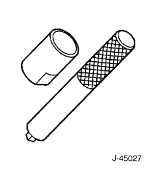 |
J-45027
Tensioner Tool
|
 |
J-8062
Valve Spring Compressor
|
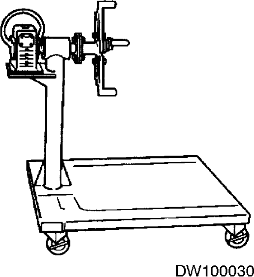 |
DW100-030
Engine Overhaul stand
|
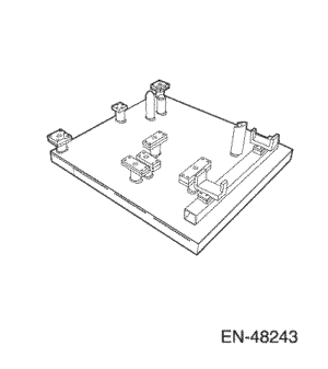 |
EN-48243
Engine Assembly Remove/Install Pallet
|
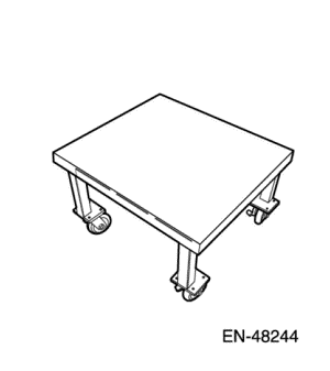 |
EN-48244
Engine Assembly Remove/Install Pallet Supporter
|
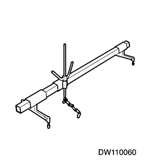 |
DW110-060
Engine Assembly Support Fixture
|


| Step | Action | Value(s) | Yes | No |
| 1 |
Are drippings present?
|
-
|
Go to Step 2
|
System OK
|
| 2 |
Can you identify the type of fluid and the approximate location of the leak?
|
-
|
Go to Step 10
|
Go to Step 3
|
| 3 |
Can you identify the type of fluid and the approximate location of the leak?
|
-
|
Go to Step 10
|
Go to Step 4
|
| 4 |
Can you identify the type of fluid and the approximate location of the leak?
|
-
|
Go to Step 10
|
Go to Step 5
|
| 5 |
Can you identify the type of fluid and the approximate location of the leak?
|
-
|
Go to Step 10
|
Go to Step 6
|
| 6 |
Can you identify the type of fluid and the approximate location of the leak?
|
-
|
Go to Step 10
|
Go to Step 7
|
| 7 |
Can you identify the type of fluid and the approximate location of the leak?
|
-
|
Go to Step 10
|
Go to Step 8
|
| 8 |
Use the black light kit in order to identify the type of fluid, and the approximate location of the leak. Refer to the manufacturer's instructions when using the tool.
Can you identify the type of fluid and the approximate location of the leak?
|
-
|
Go to Step 10
|
Go to Step 9
|
| 9 |
Can you identify the type of fluid and the approximate location of the leak?
|
-
|
Go to Step 10
|
System OK
|
| 10 |
Is there mechanical damage, or customer modifications to the engine?
|
-
|
Go to Step 11
|
System OK
|
| 11 |
Repair or replace all damaged or modified components.
Does the engine still leak oil?
|
-
|
Go to Step 11
|
System OK
|
Cause
|
Correction
|
|
High oil pressure.
|
|
|
Worn, damaged, or improperly installed accessory drive belt - severe cracking, bumps or missing segments.
A misfire DTC may be present without an actual misfire condition.
|
|
|
Worn, damaged, or improperly installed accessory drive system components.
A misfire DTC may be present without an actual misfire condition.
|
|
|
Damaged, loose or improperly installed crankshaft pulley.
A misfire DTC may be present without an actual misfire condition.
|
|
|
Worn, damaged, or improperly installed crankshaft reluctor wheel.
A worn or damaged crankshaft reluctor wheel can result in different symptoms depending on the severity and location of the wear or damage.
|
|
|
Damaged, loose or improperly installed engine flywheel.
A misfire DTC may be present without an actual misfire condition.
|
|
|
Damaged, improperly installed or restricted exhaust system, collapsed or dented pipes, plugged mufflers or malfunctioning catalytic converters.
A DTC may be present without an actual fault condition.
|
|
|
Worn, damaged or improperly installed vacuum hoses.
|
|
|
Damaged or improperly installed electronic throttle body.
|
|
|
Damaged or improperly installed intake manifold.
|
|
|
Damaged or improperly installed cylinder head.
Oil consumption may or may not cause the engine to misfire.
|
|
|
Worn, damaged, loose or broken valve spring.
|
|
|
Worn, damaged or stuck valve, carbon on the valve stem or valve seat.
|
|
|
Worn or damaged valve guide.
|
|
|
Worn, damaged or dirty valve lifter.
|
|
|
Worn or damaged camshaft lobe.
|
|
|
Worn, damaged or loose timing chain and sprockets.
|
|
|
Worn, damaged or improperly installed piston.
Pistons must be installed with the mark, or dimple, on the top of the piston, facing the front of the engine; piston pins must be centered in the connecting rod pin bore.
Oil consumption may or may not cause the engine to misfire.
|
|
Cause
|
Correction
|
|
Worn, damaged, or improperly installed accessory drive belt - severe cracking, bumps or missing segments.
A misfire DTC may be present without an actual misfire condition.
|
|
|
Worn, damaged, or improperly installed accessory drive system components.
A misfire DTC may be present without an actual misfire condition.
|
|
|
Worn, damaged, improperly installed or loose crankshaft pulley.
A misfire code may be present without an actual misfire condition.
|
|
|
Worn, damaged, improperly installed or loose engine flywheel.
A misfire code may be present without an actual misfire condition.
|
|
|
Worn, damaged or improperly installed piston.
Pistons must be installed with the mark, or dimple, on the top of the piston, facing the front of the engine; piston pins must be centered in the connecting rod pin bore.
Oil consumption may or may not cause the engine to misfire.
|
|
|
Worn, damaged or improperly installed crankshaft thrust bearing.
A misfire code may be present without an actual misfire condition.
|
|
Cause
|
Correction
|
|
Worn, damaged or stuck valve, carbon on the valve stem or valve seat.
|
|
|
Worn, damaged or dirty valve lifter.
|
|
|
Worn or damaged camshaft lobe.
|
|
|
Worn, damaged or loose timing chain and sprockets.
|
|
Cause
|
Correction
|
|
Damaged or improperly installed cylinder head.
Coolant consumption may or may not cause the engine to misfire.
|
|
Cause
|
Correction
|
|
Worn or damaged valve.
|
|
|
Worn, damaged or improperly installed piston rings.
Piston rings must be installed with the mark, or dimple, on the top of the piston ring, facing up.
|
|
Cause
|
Correction
|
|
Incorrect engine oil, viscosity.
|
|
|
Incorrect oil filter, without anti-drainback feature.
|
|
|
Worn, damaged, or improperly installed oil filter by-pass valve.
|
|
|
High valve lifter leak down rate.
|
|
|
Worn, damaged, or improperly installed crankshaft thrust bearing.
|
|
Cause
|
Correction
|
|
Low oil pressure.
|
|
|
Improper lubrication of the valve train components.
|
|
|
Broken valve spring.
|
|
|
Worn, damaged or stuck valves, carbon on the valve stem or valve seat.
|
|
|
Worn or damaged valve guide.
|
|
|
Worn, damaged or dirty valve lifter.
|
|
|
Worn or damaged camshaft lobes.
|
|
|
Worn, damaged, improperly installed or loose timing chain and sprockets.
|
|
|
Worn, damaged or improperly installed chain belt tensioner, if equipped.
|
|
Cause
|
Correction
|
|
Low oil pressure.
|
|
|
Detonation or spark knock.
|
|
|
Worn, damaged, or improperly installed accessory drive belt - severe cracking, bumps or missing segments in the accessory drive belt.
|
|
|
Worn, damaged, or improperly installed accessory drive system components.
|
|
|
Worn, damaged, or improperly installed crankshaft pulley.
|
|
|
Worn, damaged, or improperly installed engine flywheel.
|
|
|
Worn, damaged, or improperly installed torque converter.
|
|
|
Damaged oil pan, contacting the oil pump screen - an oil pan that has been damaged may loosen, improperly position, or restrict oil flow at the oil pump screen, preventing proper oil flow to the oil pump.
|
|
|
Worn, damaged, improperly installed or restricted oil pump screen - an oil pan that has been damaged may loosen, improperly position, or restrict oil flow at the oil pump screen, preventing proper oil flow to the oil pump.
|
|
|
Worn, damaged, or improperly installed piston - pistons must be installed with the mark, or dimple, on the top of the piston, facing the front of the engine.Piston pins must be centered in the connecting rod pin bore.
|
|
|
Worn, damaged, or improperly installed connecting rod bearing.
|
|
|
Worn, damaged, or improperly installed crankshaft bearing.
|
|
Cause
|
Correction
|
|
Low oil pressure.
|
|
|
Detonation or spark knock.
|
|
|
Worn, damaged, or improperly installed engine flywheel.
|
|
|
Worn, damaged, or improperly installed torque converter.
|
|
|
Worn, damaged, or improperly installed pistons-pistons must be installed with the mark, or dimple, on the top of the piston, facing the front of the engine.Piston pins must be centered in the connecting rod pin bore.
|
|
|
Worn, damaged, or improperly installed connecting rod bearing.
|
|
|
Worn, damaged, or improperly installed crankshaft bearing.
|
|
Cause
|
Correction
|
|
Seized accessory drive system component.
|
|
|
Hydraulically locked cylinder.
|
|
|
Seized automatic transaxle torque converter.
|
|
|
Seized manual transaxle.
|
|
|
Broken timing chain and/or gears.
|
|
|
Seized crankshaft.
|
|
|
Material in cylinder.
|
|
|
Seized crankshaft or connecting rod bearings.
|
|
|
Bent or broken connecting rod.
|
|
|
Broken crankshaft.
|
|
Cause
|
Correction
|
|
|
|
Cracked intake manifold or failed gasket.
|
Replace the components as required.
|
|
Faulty cylinder head gasket.
|
Replace the head gasket and components as required. Refer to Section 1C2, Engine Mechanical - HFV6 3.2L.
|
|
Warped cylinder head.
|
Machine the cylinder head to the proper flatness, if applicable and replace the cylinder head gasket. Refer to Section 1C2, Engine Mechanical - HFV6 3.2L.
|
|
Cracked cylinder head.
|
Replace the cylinder head and gasket.
|
|
Cracked cylinder liner or engine block.
|
Replace the components as required.
|
|
Cylinder head or engine block porosity.
|
Replace the components as required.
|
Cause
|
Correction
|
|
|
|
Faulty cylinder head gasket.
|
Replace the head gasket and components as required. Refer to Section 1C2, Engine Mechanical - HFV6 3.2L.
|
|
Warped cylinder head.
|
Machine the cylinder head to proper flatness, if applicable, and replace the cylinder head gasket. Refer to Section 1C2, Engine Mechanical - HFV6 3.2L.
|
|
Cracked cylinder head.
|
Replace the cylinder head and gasket.
|
|
Cracked cylinder liner or engine block.
|
Replace the components as required.
|
|
Cylinder head or engine block porosity.
|
Replace the components as required.
|
| Step | Action | Value(s) | Yes | No |
| 1 |
Did you review the Symptoms - Engine Mechanical diagnostic information, and perform the necessary inspections?
|
-
|
Go to Step 2
|
Go to Symptoms
|
| 2 |
Verify that there is a chirping noise.
Does the engine make the chirping noise?
|
-
|
Go to Step 3
|
Go to Diagnostic Aids
|
| 3 |
Does the chirping noise still exist?
|
-
|
Go to Step 4
|
|
| 4 |
Inspect for severe drive belt pilling exceeding 1/3 of the drive belt groove depth.
Does the drive belt grooves have pilling?
|
-
|
Go to Step 5
|
Go to Step 6
|
| 5 |
Clean the accessory drive belt pulley(s) with a suitable wire brush.
Were the accessory drive belt pulley(s) cleaned?
|
-
|
Go to Step 15
|
-
|
| 6 |
Inspect for a misaligned accessory drive pulley(s).
Is there a misaligned pulley(s)?
|
-
|
Go to Step 7
|
Go to Step 8
|
| 7 |
Replace and/or repair the misaligned accessory drive pulley(s).
Were the misaligned accessory drive pulley(s) replaced and/or repaired?
|
-
|
Go to Step 15
|
-
|
| 8 |
Inspect for a bent or cracked accessory drive bracket(s).
Is there a bent and/or cracked accessory drive bracket(s)?
|
-
|
Go to Step 9
|
Go to Step 10
|
| 9 |
Replace the bent and/or cracked accessory drive bracket(s).
Was the bent and/or cracked accessory drive bracket(s) replaced?
|
-
|
Go to Step 15
|
-
|
| 10 |
Inspect for incorrect, loose and/or missing fasteners.
Were there any incorrect, loose, and/or missing fasteners found?
|
-
|
Go to Step 11
|
Go to Step 12
|
| 11 |
Were the fasteners replaced and/or tightened?
|
-
|
Go to Step 15
|
-
|
| 12 |
Inspect for a bent accessory drive pulley(s).
Was a bent accessory drive pulley(s) found?
|
-
|
Go to Step 13
|
Go to Step 14
|
| 13 |
Replace the bent accessory drive pulley(s).
Was the bent accessory drive pulley(s) replaced?
|
-
|
Go to Step 15
|
-
|
| 14 |
Replace the drive belt. Refer to Section 1C2, Engine Mechanical - HFV6 3.2L.
Was the drive belt replaced?
|
-
|
Go to Step 15
|
-
|
| 15 |
Does the chirping noise still exist?
|
-
|
-
|
System OK
|
| Step | Action | Value(s) | Yes | No |
| 1 |
Did you review the Symptoms - Engine Mechanical diagnostic information, and perform the necessary inspections?
|
-
|
Go to Step 2
|
|
| 2 |
Verify that there is a squealing noise.
Does the engine make the squeal noise?
|
-
|
Go to Step 3
|
Go to Diagnostic Aids
|
| 3 |
Does the chirping noise still exist?
|
-
|
Go to Step 4
|
|
| 4 |
Inspect for a seized accessory drive component bearing or a faulty accessory drive component.
Did you find and correct the condition?
|
-
|
Go to Step 9
|
Go to Step 5
|
| 5 |
Inspect the drive belt tensioner for proper operation. Refer to Drive Belt Tensioner Diagnosis.
Did you find and correct the condition?
|
-
|
Go to Step 9
|
Go to Step 6
|
| 6 |
Check for the correct length drive belt.
Did you find and correct the condition?
|
-
|
Go to Step 9
|
Go to Step 7
|
| 7 |
Inspect for a misaligned pulley.
Did you find and correct the condition?
|
-
|
Go to Step 9
|
Go to Step 8
|
| 8 |
Inspect for an incorrect size pulley.
Did you find and correct the condition?
|
-
|
Go to Step 9
|
-
|
| 9 |
Does the squealing noise still exist?
|
-
|
-
|
System OK
|
| Step | Action | Value(s) | Yes | No |
| 1 |
Did you review the Symptoms - Engine Mechanical diagnostic information, and perform the necessary inspections?
|
-
|
Go to Step 2
|
|
| 2 |
Verify that there is a whining noise.
Does the engine make the whine noise?
|
-
|
Go to Step 3
|
Go to Diagnostic Aids
|
| 3 |
Does the whining noise still exist?
|
-
|
Go to Step 4
|
|
| 4 |
Did you find and correct the condition?
|
-
|
Go to Step 5
|
-
|
| 5 |
Does the whining still exist?
|
-
|
-
|
System OK
|
| Step | Action | Value(s) | Yes | No |
| 1 |
Did you review the Symptoms - Engine Mechanical diagnostic information, and perform the necessary inspections?
|
-
|
Go to Step 2
|
|
| 2 |
Verify that there is a rumbling noise.
Does the engine make the rumbling noise?
|
-
|
Go to Step 3
|
Go to Diagnostic Aids
|
| 3 |
Does the chirping noise still exist?
|
-
|
Go to Step 4
|
|
| 4 |
Inspect the drive belt for damage, separation, or sections of missing ribs.
Were any of these conditions found?
|
-
|
Go to Step 7
|
Go to Step 5
|
| 5 |
Inspect for severe pilling of more than 1/3 of the drive belt groove depth.
Do the drive belt grooves have pilling?
|
-
|
Go to Step 6
|
Go to Step 7
|
| 6 |
Did you complete the repair?
|
-
|
Go to Step 8
|
-
|
| 7 |
Install a new drive belt. Refer to Section 1C2, Engine Mechanical - HFV6 3.2L.
Did you complete the replacement?
|
-
|
Go to Step 8
|
-
|
| 8 |
Does the rumbling noise still exist?
|
-
|
-
|
System OK
|
| Step | Action | Value(s) | Yes | No |
| 1 |
Did you review the Symptoms - Engine Mechanical diagnostic information, and perform the necessary inspections?
|
-
|
Go to Step 2
|
|
| 2 |
Verify that the vibration is engine related.
Does the engine make the vibration?
|
-
|
Go to Step 3
|
Go to Diagnostic Aids
|
| 3 |
Does the engine still make the vibration?
|
-
|
Go to Diagnostic Starting Point - Vibration Diagnosis and Correction in Vibration Diagnosis and Correction
|
Go to Step 4
|
| 4 |
Inspect the drive belt for wear, damage, debris build-up and missing drive belt ribs.
Were any of these conditions found?
|
-
|
Go to Step 5
|
Go to Step 6
|
| 5 |
Install a new drive belt. Refer to Section 1C2, Engine Mechanical - HFV6 3.2L.
Did you complete the replacement?
|
-
|
Go to Step 11
|
-
|
| 6 |
Inspect for incorrect, loose and/or missing fasteners.
Were any of these conditions found?
|
-
|
Go to Step 7
|
Go to Step 8
|
| 7 |
Replace any incorrect and/or missing fastener.Tighten any loose fasteners. Refer to "Fastener Tightening Specifications"
in this section.
Were the fasteners replaced and/or tightened?
|
-
|
Go to Step 11
|
-
|
| 8 |
Inspect for damaged fan blades or a bent fan clutch shaft.
Did you find and correct the condition?
|
-
|
Go to Step 11
|
Go to Step 9
|
| 9 |
Inspect for a bent water pump shaft.
Did you find and correct the condition?
|
-
|
Go to Step 11
|
Go to Step 10
|
| 10 |
Inspect for bent or cracked accessory drive bracket(s).
Did you find and correct the condition?
|
-
|
Go to Step 11
|
-
|
| 11 |
Does the vibration still exist?
|
-
|
-
|
System OK
|
| Step | Action | Value(s) | Yes | No |
| 1 |
Did you review the Symptoms - Engine Mechanical diagnostic information, and perform the necessary inspections?
|
-
|
Go to Step 2
|
|
| 2 |
Inspect for a damaged drive belt.
Was a damaged drive belt found?
|
-
|
Go to Step 3
|
Go to Step 4
|
| 3 |
Install a new drive belt. Refer to Section 1C2, Engine Mechanical - HFV6 3.2L.
Does the drive belt continue to fall off?
|
-
|
Go to Step 4
|
System OK
|
| 4 |
Inspect for misaligned accessory drive pulley.
Did you find and correct the condition?
|
-
|
Go to Step 12
|
Go to Step 5
|
| 5 |
Inspect for a bent or dented accessory drive pulley.
Did you find and correct the condition?
|
-
|
Go to Step 12
|
Go to Step 6
|
| 6 |
Inspect for a bent or a cracked accessory drive bracket(s).
Did you find and correct the condition?
|
-
|
Go to Step 12
|
Go to Step 7
|
| 7 |
Inspect for incorrect, loose and/or missing fasteners.
Were there any incorrect, loose and/or missing fasteners?
|
-
|
Go to Step 8
|
Go to Step 9
|
| 8 |
Does the drive belt continue to fall off?
|
-
|
Go to Step 9
|
System OK
|
| 9 |
Test the drive belt tensioner for correct operation. Refer to Drive Belt Tensioner Diagnosis.
Does the drive belt tensioner operate correctly?
|
-
|
Go to Step 11
|
Go to Step 10
|
| 10 |
Replace the drive belt tensioner. Refer to Drive Belt Tensioner Replacement.
Does the drive belt continue to fall off?
|
-
|
Go to Step 11
|
System OK
|
| 11 |
Inspect for a failed drive belt idler and/or tensioner pulley bearings.
Did you find and repair the condition?
|
-
|
Go to Step 12
|
-
|
| 12 |
Run the engine in order to verify the repair.
Does the drive belt still fall off?
|
-
|
-
|
System OK
|
| Step | Action | Value(s) | Yes | No |
| 1 |
Did you review the Symptoms - Engine Mechanical diagnostic information, and perform the necessary inspections?
|
-
|
Go to Step 2
|
|
| 2 |
Inspect the drive belt(s) for proper installation.
Is the drive belt installed properly?
|
-
|
Go to Step 5
|
Go to Step 3
|
| 3 |
Inspect for the correct drive belt.
Is the correct drive belt installed?
|
-
|
Go to Step 5
|
Go to Step 4
|
| 4 |
Inspect the drive belt for signs of rubbing against a bracket, hose, or wiring harness.
Was the drive belt rubbing against anything?
|
-
|
Go to Step 5
|
Go to Diagnostic Aids
|
| 5 |
Replace the drive belt. Refer to Section 1C2, Engine Mechanical - HFV6 3.2L.
Did you complete the replacement?
|
-
|
Go to Step 6
|
-
|
| 6 |
Run the engine in order to verify the repair.
Is there still excessive drive belt wear?
|
-
|
-
|
System OK
|
| © Copyright Chevrolet Europe. All rights reserved |


