SECTION 1D3
ENGINE COOLING - HFV6 3.2L
Caution : Disconnect the negative battery cable before removing or installing any electrical unit or when a tool or equipment could easily come in contact with exposed electrical terminals. Disconnecting this cable will help to prevent personal injury and damage to the vehicle. The ignition must also be in LOCK unless otherwise noted.
SPECIFICATIONS
Cooling System Specifications
Application | Description | Unit | Standard |
Cooling System | Cooling Type | - | Pressurized |
Coolant | Type | - | Dexcool/Silicate Based Coolant |
Capacity | L (qt) | 10 (10.57) |
Thermostat | Type | - | Wax Pellet |
Temperature (Opened Initially) | °C (°F) | 82 °C (179.6 °F) |
Temperature (Completely Opened) | °C (°F) | 95 °C (203 °F) |
Cooling Fan | Type | - | Electrical Dual Fan |
Number of Blade | EA | 5(Main) / 7(Aux) |
Diameter | mm (in.) | Main : 340 (13.4) / Aux : 320 (12.6) |
ON Temperature at Low Speed | °C (°F) | 100 (212) |
OFF Temperature at Low Speed | °C (°F) | 98 (208.4) |
ON Temperature at High Speed | °C (°F) | 110 (230) |
OFF Temperature at High Speed | °C (°F) | 108 (226.4) |
Surge Tank | Open Pressure of the Pressure Valve | kPa | 140 |
Open Pressure of the Vacuum Valve | kPa | 10 |
Water Pump | Type | - | Centrifugal |
Impeller Diameter | mm (in.) | 55 (2.17) |
Number of Impeller Blade | EA | 6 |
Radiator | Type | - | Cross Flow |
Core Width | mm (in.) | 673 (26.50) |
Core Height | mm (in.) | 511 (20.12) |
Core Depth | mm (in.) | 27 (1.063) |
Minimum Cooling Capacity | Kcal/h | 83,000 |
Coolant Temperature Sensor (CTS) | Type | - | NTC |
Signal Voltage (at normal engine temp.) | V | 1.0~2.0 |
Resistance (at –40°C) | kΩ | 100.78 |
Resistance (at –20°C) | kΩ | 24.75~33.26 |
Resistance (at 0°C) | kΩ | 8.38~10.61 |
Resistance (at 40°C) | kΩ | 1.37~1.56 |
Resistance (at 80°C) | kΩ | 0.32~0.35 |
Resistance (at 120°C) | kΩ | 0.093~0.107 |
Fastener Tightening Specifications
Application | N•m | Lb-Ft | Lb-In |
Condenser, Radiator, Fan Module (CRFM) Assembly Support Bracket Mounting Bolt | 50 | 37 | - |
CRFM Assembly Support Bracket Through Bolt and Nut | 50 | 37 | - |
Fan Assembly Mounting Bolts | 4 | - | 35 |
Fan Blade Retaining Nut | 5.6 | - | 50 |
Fan Motor Retaining Screws | 3.5 | - | 31 |
Heater Inlet and Outlet Pipe Retaining Bolts | 12 | - | 106 |
Radiator Upper Left and Right Bracket Retaining Bolts | 20 | 15 | - |
Surge Tank Mounting Bolt and Nut | 8 | - | 71 |
Thermostat Housing Mounting Bolts | 10 | - | 89 |
Water Outlet Port Attaching Bolt | 10 | - | 89 |
Water Pipe to Thermostat Housing Attaching Bolt | 20 | 15 | - |
Water Pipe to Cylinder Head Attaching Bolt | 33 | 24 | - |
Water Pump Mounting Bolts | 25 | 18 | - |
Water Pump Pulley Retaining Bolts | 12 | - | 106 |
COMPONENT LOCATOR
Radiator and Fan
- Radiator Upper Bracket
- Lower Radiator Bumper
- Radiator
- Main Cooling Fan
- Auxiliary Cooling Fan
- Main Cooling Fan Motor
- Auxiliary Cooling Fan Motor
- Cooling Fan Shroud Assembly
- Coolant Drain Cock
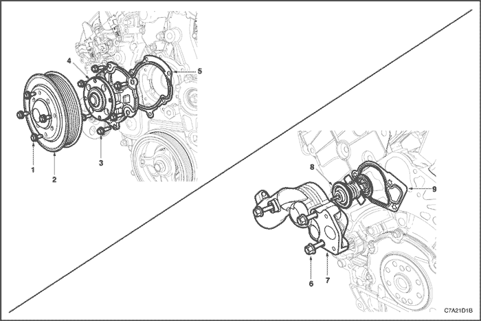
Water Pump and Thermostat
- Water Pump Pulley Bolt
- Water Pump Pulley
- Water Pump Bolt
- Water Pump
- Water Pump to Engine Front Cover Gasket
- Thermostat Housing Bolt
- Thermostat Housing
- Thermostat
- Thermostat Housing to Engine Block Gasket
DIAGNOSIS
Thermostat Test
- Remove the thermostat from the vehicle. Refer to "Thermostat" in this section.
- Make sure the valve spring is tight when the thermostat is fully closed. If the spring is not tight, replace the thermostat.
- Suspend the thermostat and a thermometer in a pan of 50/50 mixture of Dex-cool/Silicate Based Coolant and water. Do not let the thermostat or the thermometer rest on the bottom of the pan because the uneven concentration of heat on the bottom could result in inaccurate temperature measurements.
- Heat the pan on a burner.
- Use the thermometer to measure the temperature of the heated solution.
- The thermostat should begin to open at 82 °C (179.6 °F) and it should be fully open at 95 °C (203 °F). If it does not open at these temperatures, replace the thermostat.
Cooling System Diagnosis
Engine Overheats
Checks | Action |
Check for a loss of the coolant. | Add the coolant. |
Check for a weak coolant solution. | Confirm that the coolant solution is a 50/50 mixture of ethylene glycol and water. |
Check the front of the radiator for any dirt, any leaves, or any insects. | Clean the front of the radiator. |
Check for leakage from the hoses, the water pump, the heater, the thermostat housing, the radiator, the core plugs, or the head gasket. | Replace any damaged components. |
Check for a faulty thermostat. | Replace a damaged thermostat. |
Check for retarded ignition timing. | Perform an ECM code diagnosis. Confirm the integrity of the timing belt. |
Check for an improperly operating electric cooling fan. | Replace the electric cooling fan. |
Check for radiator hoses that are plugged or rotted. | Replace any damaged radiator hoses. |
Check for a faulty water pump. | Replace a faulty water pump. |
Check for a faulty surge tank cap. | Replace a faulty surge tank cap. |
Check for a cylinder head or an engine block that is cracked or plugged. | Repair the damaged cylinder head or the damaged engine block. |
Loss of Coolant
Checks | Action |
Check for a leak in the radiator. | Replace a damaged radiator. |
Check for a leak in the following locations: | Replace the following parts, as needed: |
Check for loose or damaged radiator hoses, heater hoses, and connections. | Reseat the hoses. Replace the hoses or the clamps. |
Check for leaks in the water pump seal. | Replace the water pump seal. |
Check for leaks in the water pump gasket. | Replace the water pump gasket. |
Check for an improper cylinder head torque. | Tighten the cylinder head bolts to specifications. Replace the cylinder head gasket, if needed. |
Check for leaks in the following locations: - Intake manifold.
- Cylinder head gasket.
- Cylinder block plug.
- Heater core.
- Radiator drain plug.
| Repair or replace any components, as needed, to correct the leak. |
Engine Fails to Reach Normal Operating Temperature or Cool Air from the Heater
Checks | Action |
Check to determine if the thermostat is stuck open or is the wrong type of thermostat. | Install a new thermostat of the correct type and heat range. |
Check the coolant level to determine if it is below the MIN mark on the surge tank. | Add sufficient coolant to raise the fluid to the specified mark on the surge tank. |
MAINTENANCE AND REPAIR
ON-VEHICLE SERVICE


Draining and Refilling the Cooling System
Important : The cooling sysem in the vehicle is designed to use either Dex-cool coolant, which is red in color, or silicate based coolant, which is blue. These two types of coolant are not compatible with each other and should never be mixed. Even if the cooling system has been completely drained before a refill, do not switch types of coolant.
Caution : Do not remove the surge tank cap while the engine and the radiator are hot. Scalding fluid and steam may be blown out high pressure.
- Place a pan below the vehicle to catch the draining coolant.
- Remove the surge tank cap.
- Unplug the drain cock.
Caution : Dispose of the used coolant to a used coolant holding tank to be picked up with the used oil for disposal. Never pour the used coolant down the drain.
- Catch the escaping fluid in a drain pan.
- Remove all sludge and dirt from inside of the surge tank. Refer to "Surge Tank" in this section.
- Plug the drain cock.
- Add the clean water to the surge tank.
- Fill the tank slowly so that the upper reservoir hose remains above the water line. This allows the air inside the cooling system to escape.
- Start the engine.
- Run the engine until the thermostat opens. You can tell the thermostat is open when both radiator hoses are hot to the touch.

- Stop the engine.
- Repeat steps 1 through 9 until the drained water is clear and free of coolant and rust.
Notice : Never use an antifreeze mixture more concentrated than 60% antifreeze to 40% water. The solution freezing point increases above this concentration.
- Fill the cooling system through the surge tank with a mixture of Dex-cool and water. The mixture must be at least 50% antifreeze, but not more than 60% antifreeze.
- Fill the surge tank to the specified MAX fill mark on the outside of the tank.
Thermostat
Removal Procedure
Caution : To prevent personal injury, do not remove the surge tank cap while the engine and the radiator are hot because the heat caused the system to remain under pressure. Scalding fluid and steam may be blown out high pressure.
- Drain the coolant. Refer to "Draining and Refilling the Cooling System" in this section.
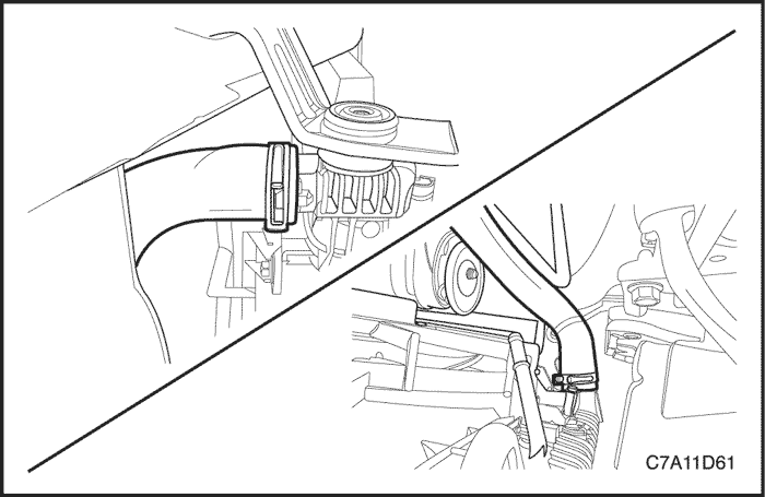
- Loosen the lower radiator hose clamp at the water pipe.
- Disconnect the lower radiator hose from the water pipe.

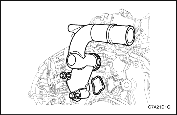
- Remove the water pipe attaching bolts from the cylinder head and the thermostat housing.
- Remove the water pipe.
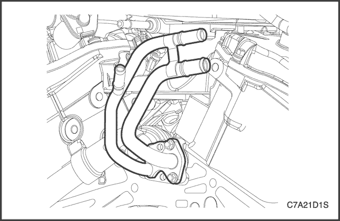
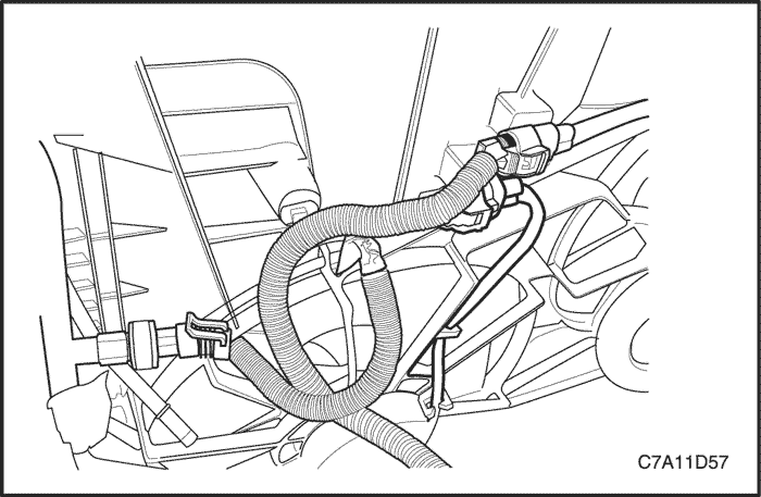
- Remove the heater inlet and outlet hose from the heater inlet and outlet pipe.
- Remove the heater inlet and outlet pipe from the thermostat housing.

- Remove the mounting bolts that hold the thermostat housing to the cylinder block.
- Remove the thermostat housing from the cylinder block.
- Remove and discard the thermostat housing to engine block gasket.
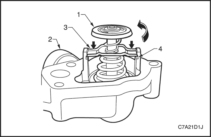
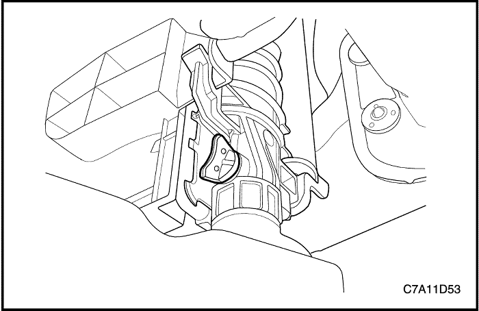
- Remove thermostat (1) from thermostat housing (2) as follows:
- a. Secure the thermostat housing by gripping in a vice fitted with soft jaws.
- b. Depress the retaining bar (3) on both sides of the thermostat and rotate the thermostat until it clears the retaining lugs (4) on the thermostat housing (2).
- c. Release the thermostat spring force.
- d. Remove the thermostat assembly from the thermostat housing.
Installation Procedure
- Install the heater inlet and outlet pipe to the thermostat housing.
Tighten
Tighten the heater inlet and outlet pipe retaining bolts to 12 N•m (106 lb-in).
- Install the thermostat into the thermostat housing.
- Ensure that the engine block and thermostat housing mating surfaces are clean and dry.
- Install a new gasket to the thermostat housing.
- Install the thermostat housing to the engine block.
Tighten
Tighten the thermostat housing attaching bolts to 10 N•m (89 lb-in).
- Install the water pipe.
Tighten
- Tighten the water pipe to thermostat housing attaching bolt to 20 N•m (15 lb-ft).
- Tighten the water pipe to cylinder head attaching bolt to 33 N•m (24 lb-ft).
- Connect the lower radiator hose to the thermostat housing.
- Connect the heater inlet and outlet hoses to the heater inlet and outlet pipe.
- Secure the lower radiator hose to the thermostat housing with a hose clamp.
- Refill the engine cooling system. Refer to "Draining and Refilling the Cooling System" in this section.
Water Pump
Removal Procedure
- Allow engine to cool to ambient temperature (less than 50(°C), then remove the coolant filler cap.
- Drain the coolant. Refer to "Draining and Refilling the Cooling System" in this section.
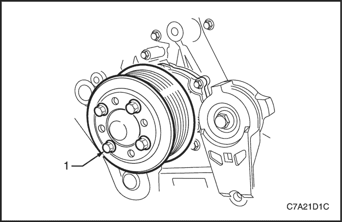
- Loosen the water pump pulley retaining bolts.

- Remove the accessory drive belt. Refer to Section 1C2, Engine Mechanical - HFV6 3.2L.
- Remove the loosened water pump pulley retaining bolts (1), then remove the pulley (2) from the hub (3).

- Remove the water pump (1) from the engine front cover.
- Remove water pump to front cover gasket (2) and discard.
Inspection Cleaning Procedure
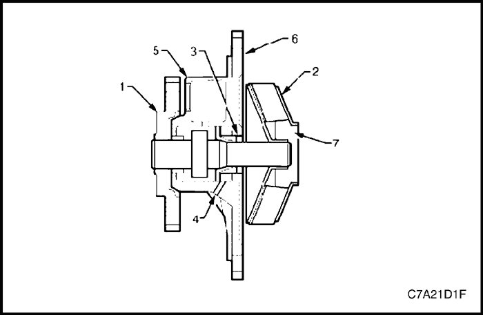
- Rotate the water pump hub (1). The hub and impeller (2) should turn straight and smoothly. If the hub wobbles, is noisy or feels rough when rotated, replace the water pump.
- Inspect the exterior of the water pump for the following:
- Damage to the water pump hub bolt threads for the water pump pulley.
- Damage to the water pump bolt holes.
- Examine the water pump shaft (3) and the weep hole (4) in the water pump housing (5) for signs of leakage. If coolant leakage is evident, replace the water pump.
- Inspect the interior of the water pump for the following:
- Damage to the water pump gasket-sealing flange surface (6).
- Damage, corrosion or restrictions to the water pump impeller.
- Damage, corrosion or restrictions to the coolant passages (7).
- Replace the water pump as necessary.
Installation Procedure
- Install a new water pump to front cover gasket (2).
- Install the water pump (1) to the engine front cover.
Tighten
Tighten the water pump retaining bolts to 25 N•m (18 lb-ft).

- Install the water pump pulley.
Tighten
Tighten the water pump pulley retaining bolts to 12 N•m (106 lb-in).
- Install the accessory drive belt. Refer to Section 1C2, Engine Mechanical - HFV6 3.2L.
- Refill the engine cooling system. Refer to "Draining and Refilling the Cooling System" in this section.

Water Outlet Port
Removal Procedure
- Loosen the clamp and disconnect the heater upper hose.
- Loosen the clamp and disconnect the water hose to surge tank.
- Remove the water outlet port (1) from the cylinder block.
- Remove water outlet port to cylinder block gasket (2) and discard.
Installation Procedure
- Install a new water outlet port to cylinder block gasket (2).
- Install the water outlet port (1) to the cylinder block.
Tighten
Tighten the water outlet port attaching bolt to 10 N•m (89 lb-in).
- Connect the heater upper hose to the water outlet port and secure the clamp.
- Connect the water hose to surge tank to the water outlet port and secure the clamp.
Cooling Fan Assembly
Removal Procedure
- Disconnect the negative battery cable.
- Remove the engine dress cover. Refer to Section 1C2, Engine Mechanical - HFV6 3.2L.
- Remove the air cleaner assembly. Refer to Section 1C2, Engine Mechanical - HFV6 3.2L.
- Disconnect the both cooling fan electrical connectors and the A/C pressure sensor connector.
- Remove the cooling fan shroud mounting bolts.
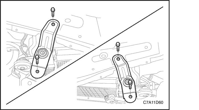
- Support the radiator and condenser before removing the condenser, radiator, fan module (CRFM) assembly support bracket.
- Remove the CRFM assembly support bracket upper bolt.
- Remove the CRFM assembly support bracket through bolt and nut.
- Remove the both CRFM assembly support brackets.

- Separate the fan shroud assembly from the radiator and carefully lower the fan shroud assembly from the vehicle.
- Remove the both main and auxiliary fan blades from the fan shroud assembly by removing the nut at the center of the fan hubs.
- Remove the both fan motor retaining screws.
- Remove the both fan motors from the shroud.
Installation Procedure
Caution : If a fan assembly is bent or damaged in any way, no attempt should be made to repair or reuse the damaged part. A bent or damaged fan assembly must be replaced with a new fan assembly. It is essential to remain the fan assemblies in proper balance. A fan assembly that is not in proper balance can fail and fly apart during use, creating extreme danger. Proper balance cannot be assured on a fan assembly that has been bent or damaged.
- Install the both fan motors and fan blades, if they were previously removed.
Tighten
- Tighten the fan motor retaining screws to 3.5 N•m (31 lb-in).
- Tighten the fan blades retaining nuts to 5.6 N•m (50 lb-in).
- Carefully lift the fan shroud assembly into the position previously removed.
- Install the CRFM assembly support bracket through bolt and nut.
Tighten
Tighten the CRFM assembly support bracket through bolt and nut to 50 N•m (37 lb-ft).
- Install the CRFM assembly support bracket mounting upper bolt to 50 N•m (37 lb-in.)
- Install the cooling fan assembly to the radiator.
Important : Be sure to slip the tab at the bottom edge of the shroud into the retaining clip at the radiator.
- Secure the cooling fan assembly to the top of the radiator with the mounting bolts.
Tighten
Tighten the cooling fan assembly mounting bolts to 4 N•m (35 lb-in).
- Connect the cooling fan electrical connectors and the A/C pressure sensor connector.
- Install the air cleaner assembly. Refer to Section 1C2, Engine Mechanical - HFV6 3.2L.
- Install the engine dress cover. Refer to Section 1C2, Engine Mechanical - HFV6 3.2L.
- Connect the negative battery cable.

Surge Tank
Removal Procedure
Caution : To prevent personal injury, do not remove the surge tank cap while the engine and the radiator are hot because the heat caused the system to remain under pressure. Scalding fluid and steam may be blown out high pressure.
- Drain the engine coolant to below the level of the surge tank.
Note : Do not drain the power steering fluid at this stage.
- Remove the power steering fluid reservoir retaining bolts and move the reservoir away from the surge tank. Refer to Section 6A, Power Steering System.
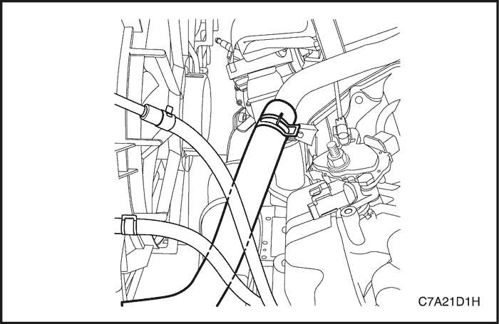
- Loosen the return hose clamp and disconnect the return hose from the top of the surge tank.
- Loosen the throttle body hose clamp and disconnect the throttle body hose from the top of the surge tank.
- Loosen the feed hose clamp and disconnect the feed hose from the bottom of the surge tank.

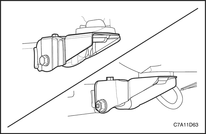
- Remove the surge tank attaching bolt and nut.
- Remove the surge tank.
- Clean the inside and the outside of the surge tank and the surge tank cap with soap and water.
- Rinse the surge tank and the cap thoroughly.
Installation Procedure
- Install the surge tank.
- Secure the surge tank with the attaching bolt and nut.
Tighten
Tighten the surge tank retaining bolt and nut to 8 N•m (71 lb-in.).
- Connect the return hose and the throttle body hose to the top of the surge tank.
- Connect the feed hose to the bottom of the surge tank.
- Secure the return hose, throttle body hose and the feed hose to the surge tank with the hose clamps.
- Fill the surge tank with the coolant to the center ridge or the MAX mark.
Radiator
Removal Procedure
- Disconnect the negative battery cable.
- Drain the engine cooling system. Refer to "Draining and Refilling the Cooling System" in this section.
- Remove the engine dress cover. Refer to Section 1C2, Engine Mechanical - HFV6 3.2L.
- Disconnect the both cooling fan electrical connectors and the A/C pressure sensor connector.
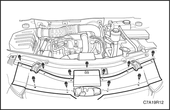
- Remove the radiator grill upper guide. Refer to Section 9R, Body Front End.
- Remove the A/C condenser upper and lower bracket from the radiator. Refer to Section 7B, Manual Control Heating, Ventilation, and Air Conditioning System.
- Hang the A/C condenser to prevent it from falling down.
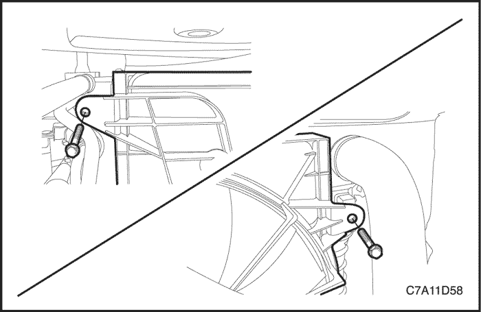
- Remove the radiator upper bracket retaining bolts.
- Remove the radiator upper brackets.
- Disconnect the transaxle cooler pipes from the lower radiator tank, if equipped.
- Loosen the upper radiator hose clamp and then disconnect the upper radiator hose from the radiator.
- Loosen the lower radiator hose clamp and then disconnect the lower radiator hose from the radiator.
- Loosen the clamp and disconnect the coolant return hose.
- Lift and carefully support the vehicle.
- Remove the condenser, radiator, fan module (CRFM) assembly support bracket mounting upper bolts.
- Remove the CRFM assembly support bracket through bolts and nuts.
- Remove the both CRFM assembly support brackets.

Caution : Do not to damage the radiator fins for the proper operation of the cooling system.
- Carefully lower the radiator and fan assembly from the vehicle.
- Remove the radiator.
- Remove the cooling fan assembly from the radiator if necessary.
Cleaning
Caution : NEVER spray water on a hot radiator. The resulting steam could cause personal injury.
Notice : The radiator fins are necessary for good heat transfer. Do not brush the fins. This may cause damage to the fins, reducing heat transfer.
Important : Remove bugs, leaves, dirt and other debris by blowing compressed air through the engine side of the radiator.
Some conditions may require the use of warm water and a mild detergent.
- Clean the radiator cooling fins.
- Straighten any damaged cooling fins.
Installation Procedure
Caution : Do not to damage the radiator fins for the proper operation of the cooling system.
- Install the cooling fan assembly if necessary.
- Install the radiator.
- Carefully lift the radiator into the position previously removed.
- Install the both CRFM assembly support brackets.
- Install the CRFM assembly support bracket through bolts and nuts.
Tighten
Tighten the CRFM assembly support bracket through bolts and nuts to 50 N•m (37 lb-ft).
- Install the CRFM assembly support bracket mounting upper bolts.
Tighten
Tighten the CRFM assembly support bracket mounting upper bolts to 50 N•m (37 lb-ft).
- Connect the lower radiator hose to the radiator and then secure the clamp.
- Connect the upper radiator hose to the radiator and then secure the clamp.
- Connect the transaxle cooler pipes to the radiator, if equipped.
- Connect the coolant return hose.
- Install the A/C condenser to the radiator.
- Install the radiator upper brackets.
Tighten
Tighten the radiator upper bracket retaining bolts to 20 N•m (15 lb-ft).
- Install the radiator grill upper guide. Refer to Section 9R, Body Front End.

- Install the engine dress cover. Refer to Section 1C2, Engine Mechanical - HFV6 3.2L.
- Fill the engine cooling system. Refer to "Draining and Refilling the Cooling System" in this section.
- Connect the negative battery.
GENERAL DESCRIPTION AND SYSTEM OPERATION
General Description
The cooling system maintains the engine temperature at an efficient level during all engine operating conditions.
When the engine is cold, the cooling system cools the engine slowly or not at all. This slow cooling of the engine allows the engine to warm up quickly.
The cooling system includes a radiator and recovery subsystem, cooling fans, a thermostat and housing, a water pump, and a water pump drive belt. The timing belt drives the water pump.
All components must function properly in order for the cooling system to operate. The water pump draws the coolant from the radiator. The coolant then circulates through water jackets in the engine block, the intake manifold, and the cylinder head. When the coolant reaches the operating temperature of the thermostat, the thermostat opens. The coolant then goes back to the radiator where it cools.This system directs some coolant through the hoses to the heater core. This provides for heating and defrosting. The surge tank is connected to the radiator to recover the coolant displaced by expansion from the high temperatures.
The surge tank maintains the correct coolant level.
The cooling system for this vehicle has no radiator cap or filler neck. The coolant is added to the cooling system through the surge tank.
Radiator
This vehicle has a lightweight tube–and–fin aluminum radiator. Plastic tanks are mounted on the right and the left sides of the radiator core.
On vehicles equipped with automatic transaxles, the transaxle fluid cooler lines run through the left radiator tank. A radiator drain cock is on this radiator. To drain the cooling system, open the drain cock.
Surge Tank
The surge tank is a transparent plastic reservoir, similar to the windshield washer reservoir.
The surge tank is connected to the radiator by a hose and to the engine cooling system by another hose. As the vehicle is driven, the engine coolant heats and expands. The portion of the engine coolant displaced by this expansion flows from the radiator and the engine into the surge tank. The air trapped in the radiator and the engine is degassed into the surge tank.
When the engine stops, the engine coolant cools and contracts. The displaced engine coolant is then drawn back into the radiator and the engine. This keeps the radiator filled with the coolant to the desired level at all times and increases the cooling efficiency.
Maintain the coolant level between the MIN and the MAX marks on the surge tank when the system is cold.
Water Pump
The water pump is a centrifugal vane impeller type pump. The pump consists of a housing and an impeller. The impeller is a flat plate mounted on the pump shaft with a series of flat or curved blades (vanes). When the impeller rotates, the coolant between the vanes is thrown outward by centrifugal force. The impeller shaft is supported by sealed bearings. The sealed bearings do not need to be lubricated. Grease cannot leak out, dirt and water cannot get in as long as the seal is not damaged or worn.
The water pump is mounted to the engine front cover and is driven by the crankshaft pulley via a multi-ribbed drive belt , turning the pump pulley , bolted to the water pump flange. Coolant enters the engine through the coolant inlet pipe and thermostat at the rear of engine and passes through the engine to the water pump on the front engine cover and exits via the coolant outlet housing located at the front of the intake manifold.
Thermostat
A wax pellet type thermostat is used in the coolant inlet passage to control the flow of coolant, providing fast engine warm up and regulating coolant temperature. The wax pellet or power element in the thermostat expands when heated and contracts when cooled. The wax pellet is connected through a piston to a valve and when the pellet is heated, pressure is exerted against a metal valve, which is forced to open.
As the pellet is cooled, the contraction allows a spring to close the valve. Thus, the valve remains closed while the coolant is cold, preventing circulation of coolant through the radiator, but allowing the coolant to circulate throughout the engine to warm it quickly and evenly. As the engine becomes warm, the pellet expands and the thermostat opens, permitting the coolant to flow through to the radiator where heat is transferred to the surrounding air, through the radiator walls.
This opening and closing of the thermostat valve permits enough coolant to enter the radiator to keep the engine within specified temperature limits.
The thermostat also provides a restriction in the cooling system, even after it has opened. This restriction creates a pressure difference, which prevents cavitation at the water pump and forces coolant to circulate through the engine block.
The thermostat begins to open at 82 °C (179.6 °F) and is fully opened at 95 °C (203 °F).
Electric Cooling Fan
Caution : Keep hands, tools, and clothing away from the engine cooling fans to help prevent personal injury. This fan is electric and can turn ON whether or not the engine is running.
Caution : If a fan blade is bent or damaged in any way, no attempt should be made to repair or reuse the damaged part. A bent or damaged fan assembly should always be replaced with a new one. Failure to do so can result in personal injury.
The cooling fans are mounted behind the radiator in the engine compartment. Cooling system on this vehicle has two cooling fans – the main fan and the auxiliary fan. The electric cooling fans increase the flow of air across the radiator fins and across the condenser on air condition (A/C) equipped vehicles. This helps to speed cooling when the vehicle is at idle or moving at low speeds.
A vehicle equipped with the A/C or Non-A/C has two fans on the one shroud. The main fan size is 340 mm (13.4 inches) in diameter with five blades, and the auxiliary fan size is 320 mm (12.6 inches) in diameter with seven blades to aid the airflow through the radiator and the condenser. Two electric fan motors attached to the center of each fan on the fan shroud assembly drive the both fans.
A/C OFF or Non-A/C Model
- The cooling fans are actuated by the electronic control module (ECM) using the serial/parallel cooling fan relay.
- The ECM will turn the cooling fans on at low speed when the coolant temperature reaches 100°C (212°F) and at high speed when the coolant temperature reaches 110°C (230°F).
- The ECM will change the cooling fans from high speed to low speed at 108°C (226.4°F) and will turn the cooling fans off at 98°C (208.4°F).
A/C ON
- The ECM will turn the cooling fans on at low speed when the A/C system is on. The ECM will change to high speed when the coolant temperature reaches 110°C (230°F) or the high side A/C pressure reaches 1760 kPa (255 psi).
- The cooling fans will return to low speed when the coolant temperature reaches 100°C (212°F) and the high side A/C pressure reaches 1347 kPa (195 psi).