MAINTENANCE AND REPAIR
ON-VEHICLE SERVICE


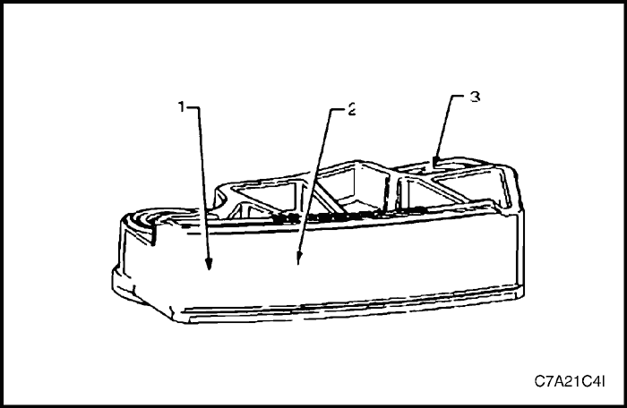
Engine Dress Cover
Removal Procedure
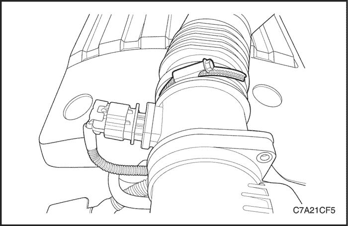
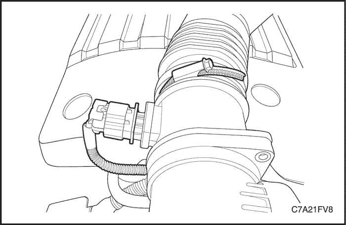
- Loosen the clamp and disconnect the flexible air intake duct from the mass air flow (MAF) sensor assembly.
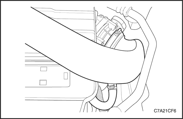
- Loosen the clamp and disconnect the air intake duct from the throttle body assembly.
- Unclip the clip and disconnect the positive crankcase ventilation (PCV) hose from the air intake duct.
- Remove the air intake duct assembly.

- Remove the engine dress cover attaching bolts and nuts.
- Remove the engine dress cover.
Installation Procedure
- Install the engine dress cover.
Tighten
Tighten the engine dress cover attaching bolts and nuts to 8 N•m (71 lb-in).
- Install the air intake duct assembly.
- Tighten the loosened clamps.
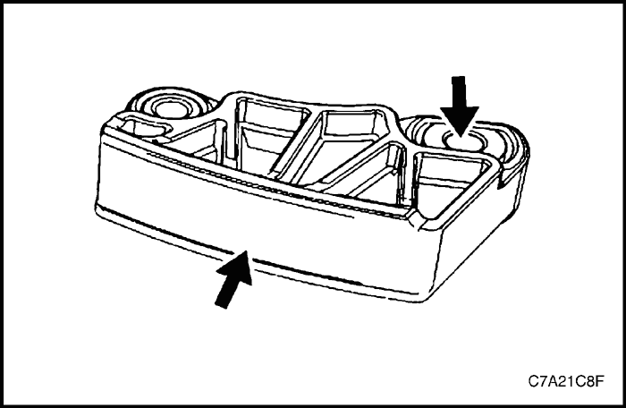
Air Cleaner Assembly
Removal Procedure
- Disconnect the negative battery cable.
- Disconnect the mass air flow (MAF) sensor connector.
- Loosen the clamp and disconnect the flexible air intake duct from the MAF sensor assembly.

- Remove the air cleaner housing bolts.
- Unclip the housing from the ball stud and then remove the air cleaner assembly.
Installation Procedure
- Install the air cleaner lower housing to the ball stud.
- Install the air cleaner housing bolts.
Tighten
Tighten the air cleaner housing attaching bolt to 6 N•m (53 lb-in).
- Install the air intake duct assembly.
- Tighten the loosened clamps.

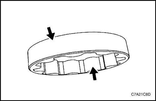
Air Cleaner Element
Removal Procedure
- Loosen the clamp and disconnect the air cleaner outlet hose from the air cleaner housing.
- Remove the air cleaner element cover screws.

- Remove the air cleaner element.
Installation Procedure
- Install the air cleaner element cover.
- Tighten the air cleaner element cover screws.
Tighten
Tighten the air cleaner element cover screws to 2 N•m (18 lb-in).
Accessory Drive Belt
Removal Procedure
- Remove the engine dress cover. Refer to "Engine Dress Cover"
in this section.
- Remove the air cleaner assembly. Refer to "Air Cleaner Assembly"
in this section.
- Remove the right front tire.
- Remove the splash shield.
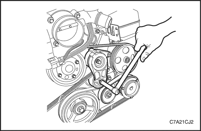
- Rotate the accessory drive belt tensioner clockwise to reduce the belt tension.
- While holding the tensioner in the reduced tension position, disconnect the belt.
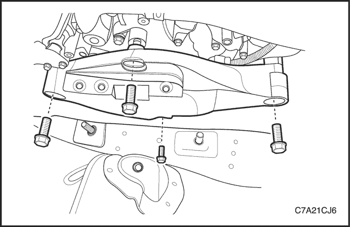
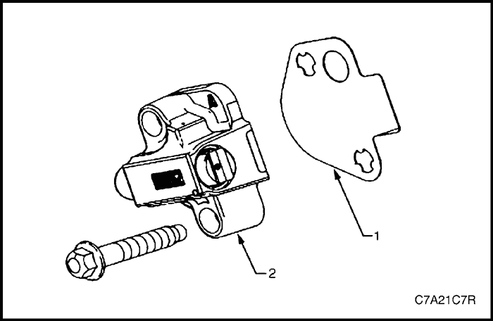
- Remove the engine mount assembly. Refer to "Engine Mount Assembly"
in this section.
- Remove the engine mount support bracket retaining bolts.
- Remove the engine mount support bracket by moving upward.
- Remove the accessory drive belt.
Installation Procedure
- Position the accessory drive belt.
- Install the engine mount support bracket.
Tighten
-
- Tighten the engine mount support bracket mounting upper bolts to 90 N•m (66 lb-ft).
- Tighten the engine mount support bracket mounting lower bolt to 50 N•m (37 lb-ft).
- Install the engine mount assembly. Refer to "Engine Mount Assembly"
in this section.
- Rotate the accessory drive belt tensioner clockwise.
- While holding the tensioner in the reduced tension position, install the belt.
- Install the splash shield.
- Install the right front tire.
- Install the air cleaner assembly. Refer to "Air Cleaner Assembly"
in this section.
- Install the engine dress cover. Refer to "Engine Dress Cover"
in this section.
Accessory Drive Belt Idler Pulley
Removal Procedure
- Remove the engine dress cover. Refer to "Engine Dress Cover"
in this section.
- Remove the air cleaner assembly. Refer to Section 1C2, Engine Mechanical - HFV6 3.2L.
- Rotate the accessory drive belt tensioner clockwise to reduce the belt tension.
- While holding the tensioner in the reduced tension position, disconnect the belt.
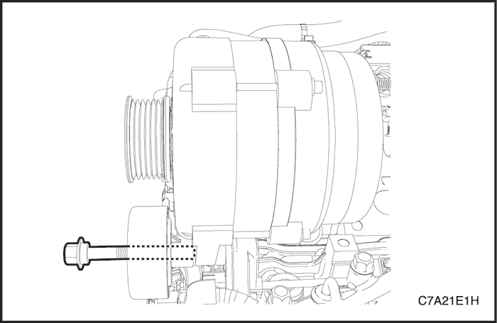
- Loosen the accessory drive belt idler pulley-to-generator through bolt.
- Carefully support the generator and remove the generator upper mounting bolts to ease the removal of the through bolt.
- Remove the accessory drive bolt idler pulley-to-generator through bolt.
- Remove the accessory drive belt idler pulley.
Installation Procedure
- Carefully support the generator and install the accessory drive belt idler pulley.
Tighten
Tighten the accessory drive belt idler pulley-to-generator through bolt to 50 N•m (37 lb-ft).
- Install the generator upper mounting bolts.
Tighten
Tighten the generator upper mounting bolt to 58 N•m (43 lb-ft).
- Rotate the accessory drive belt tensioner clockwise.
- While holding the tensioner in the reduced tension position, install the belt.
- Install the air cleaner assembly. Refer to Section 1C2, Engine Mechanical - HFV6 3.2L.
- Install the engine dress cover. Refer to Section 1C2, Engine Mechanical - HFV6 3.2L.
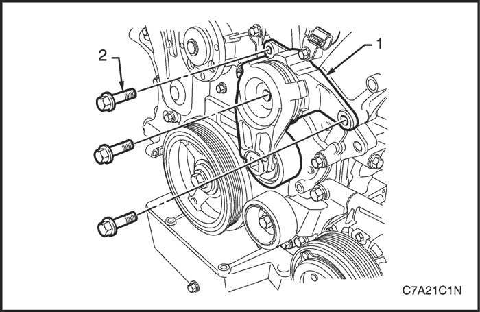
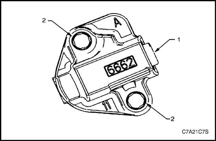
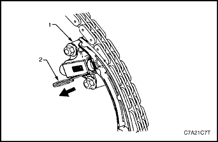
Accessory Drive Belt Tensioner Assembly
Removal Procedure
- Remove the accessory drive belt. Refer to "Accessory Drive Belt"
in this section.
- Remove the accessory drive belt tensioner.
- Disconnect the breather hose and PCV hose from the cylinder head cover.
Note : The accessory drive belt tensioner pulley is not serviced separately. If the pulley is found to be faulty, the entire tensioner assembly must be replaced.
Caution : Repairing a damaged accessory drive belt pulley should not be attempted under any circumstances.
Installation Procedure
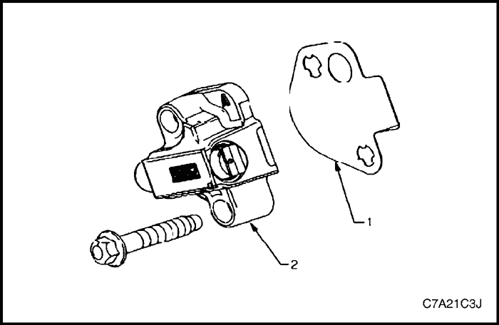
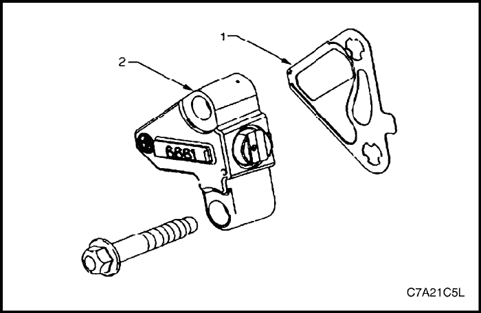
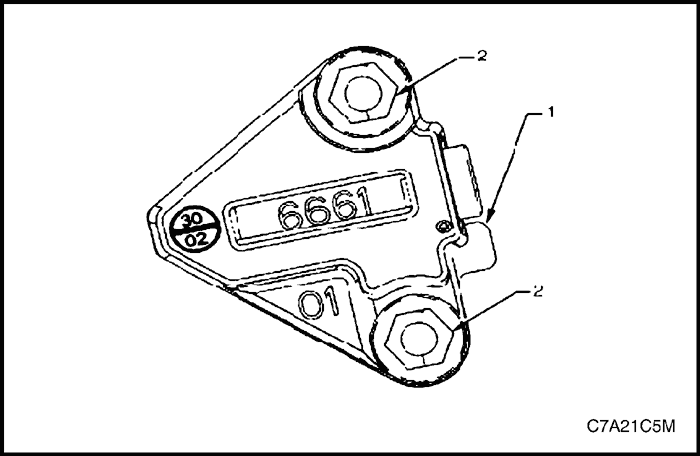
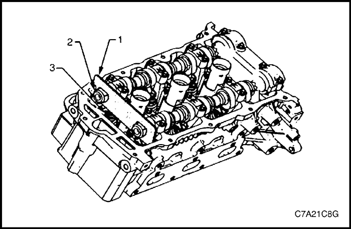
- Install the accessory drive belt tensioner assembly (1).
- Install the accessory drive belt tensioner bolts (2).
Tighten
Tighten the accessory drive belt tensioner attaching bolts to 50 N•m (37 lb-ft).
Upper Intake Manifold
Note : The intake manifold comprises of an upper and lower section. Some service procedures only require the removal of the upper intake manifold (e.g. fuel injector/spark plug servicing), while other service procedures require the removal of both the upper and lower manifold as a complete assembly (e.g. cylinder head/s). If the complete assembly needs to be removed, refer to "Intake Manifold Assembly"
in this section.
Removal Procedure
- Disconnect the battery negative cable.
- Remove the engine dress cover. Refer to "Engine Dress Cover"
in this section.
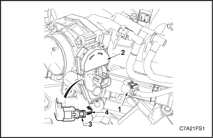
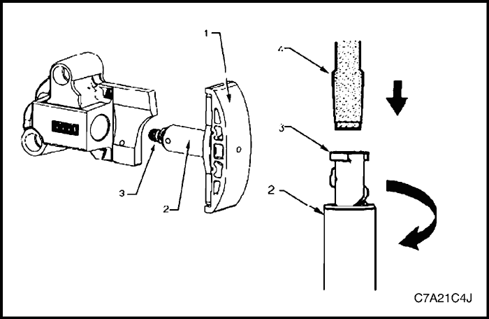
Caution : The following precautions must be followed when disconnecting the throttle body wiring connector.
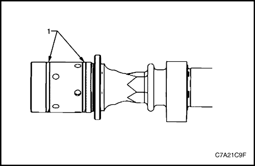
- Do not use any mechanical device such as a screwdriver to disengage the harness connector (1) from the throttle body (2).
- When retracting the throttle wiring connector lock (3), take care not to disengage the lock from the connector.
- Do not pull on the connector wires.
- Retract the throttle body wiring connector lock (3).
- While pressing the connector latch in the direction of the arrow (4), disconnect the throttle body wiring connector.
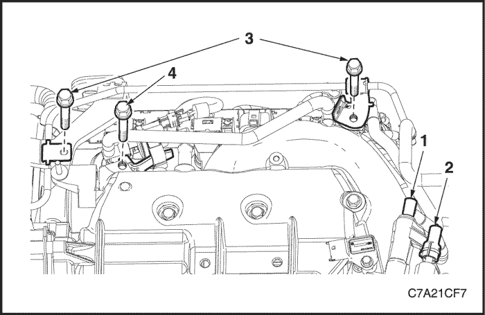
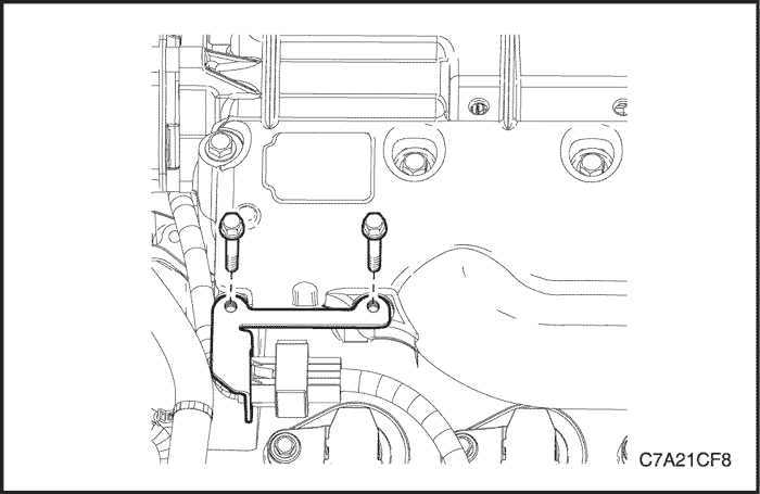
- Disconnect the positive crankcase ventilation (PCV) hose (1), evaporative (EVAP) emission purge vacuum hose (2).
- Remove the water outlet port-to-surge tank pipe bracket retaining bolts (3).
- Remove the EVAP emission purge solenoid bracket retaining bolt (4).
- Disconnect the wiring harness connector from the intake manifold tuning control (IMTC) solenoid.
- Remove the engine wiring harness mount bracket.
- Move all the necessary parts clear of the upper intake manifold assembly.
Caution : When the upper intake manifold is removed, plug each of the lower intake runner openings with lint free cloth, to stop the entry of foreign material into the engine.
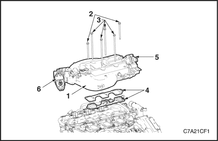
- Remove the four long (3) and two short bolts (2) attaching the upper intake manifold (1) to the cylinder heads and lower intake manifold.
Caution : Do not reuse the upper to lower intake manifold gaskets.
- Lift the upper intake manifold clear from the lower half and then remove the upper intake manifold from the engine.
- Remove and discard the upper to lower intake manifold gaskets (4).
- Remove the IMTC solenoid (5) and the throttle body assembly (6), if necessary.
Clean
Caution : Due to the aluminium alloy construction of the intake manifold, wire brushes and steel scrapers must not be used during the cleaning process, as damage to sealing surfaces may occur. Use of a wooden or plastic scraper is preferred.
- Clean mating surfaces ensuring any gasket material is removed.
- Clean the manifold using a suitable solvent.
- Dry the timing components with compressed air.
Inspection
- Inspect the intake manifold for the following fault conditions:
- Damaged sealing and mating surfaces.
- Damaged lower intake manifold gasket.
- Damage or excessive debris on the threaded and through holes.
- Cracks or damage to the intake manifold body.
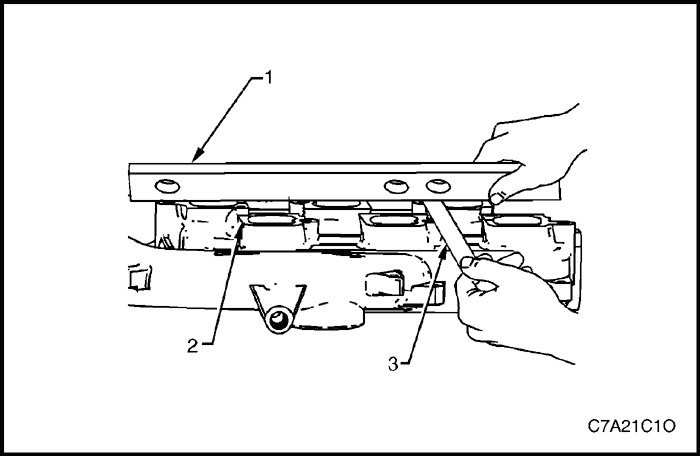
- Place a straight edge (1) across the upper intake manifold sealing surface (2).
- Using a feeler gauge (3), measure the clearance between the manifold and the straight edge.
- If the clearance between the upper intake manifold sealing surface and the straight edge exceeds the specified maximum warpage, replace the manifold.
- Upper manifold maximum warpage : 0.05 mm.
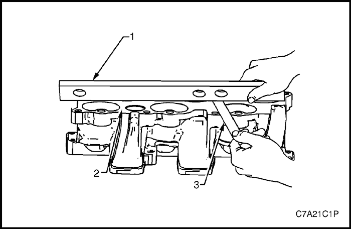
- Place a straight edge (1) across the lower intake manifold sealing surface (2).
- Using a feeler gauge (3), measure the clearance between the manifold and the straight edge.
- If the clearance between the lower intake manifold sealing surface and the straight edge exceeds the specified maximum warpage, replace the manifold.
- Lower manifold maximum warpage : 0.05 mm.
Installation Procedure
- Installation should follow the removal procedure in the reverse order, noting the following.
- Only new gaskets are to be fitted between the upper and lower intake manifolds.
Caution : Tighten the intake manifold bolts in a circular pattern starting at the center bolt and moving outward.
- Install the upper intake manifold.
Tighten
Tighten the upper intake manifold to lower intake manifold and cylinder head attaching bolts to 23 N•m (17 lb-ft).
- Connect the IMTC connector.
- Connect the throttle body connector.
- Install the EVAP emission purge solenoid bracket retaining bolt (4).
- Install the water outlet port-to-surge tank pipe bracket retaining bolts (3).
- Connect the EVAP emission vacuum hose (2) and PCV hose (1) to the upper intake manifold.
- Install the engine wiring harness mount bracket.
Intake Manifold Assembly
Note : The intake manifold comprises of an upper and lower section. Some service procedures only require the removal of the upper intake manifold (e.g. fuel injector/spark plug servicing), while other service procedures require the removal of both the upper and lower manifold as a complete assembly (e.g. cylinder head/s). If only the upper intake manifold needs to be removed, refer to "Upper Intake Manifold"
in this section.
Removal Procedure
- Depressurise the fuel system. Refer to Section 1F3, Engine Controls - HFV6 3.2L.
- Disconnect the negative battery cable.
- Remove the air intake duct.
- Remove the engine dress cover. Refer to "Engine Dress Cover"
in this section.
Caution : The following precautions must be followed when disconnecting the throttle body wiring connector.
- Do not use any mechanical device such as a screwdriver to disengage the harness connector (1) from the throttle body (2).
- When retracting the throttle wiring connector lock (3), take care not to disengage the lock from the connector.
- Do not pull on the connector wires.
- Retract the throttle body wiring connector lock (3).
- While pressing the connector latch in the direction of the arrow (4), disconnect the throttle body wiring connector.
- Disconnect the positive crankcase ventilation (PCV) hose (1), evaporative (EVAP) emission purge vacuum hose (2).
- Remove the water outlet port-to-surge tank pipe bracket retaining bolts (3).
- Remove the EVAP emission purge solenoid bracket retaining bolt (4).
- Disconnect the wiring harness connector from the intake manifold tuning control (IMTC) solenoid.
- Remove the engine wiring harness mount bracket.
- Move all the necessary parts clear of the upper intake manifold assembly.
Caution : Plug the fuel feed hose opening after removal to prevent dirt and other contaminants from entering the fuel system.
- Disconnect the fuel feed line from the fuel rail.
- Remove the wiring harness connector (2) from the EVAP valve (1).
- Disconnect the quick connect (3) from the rear of the EVAP valve, as follows:
-
- a. Squeeze the two barbed lugs together, push the quick connect into the valve, then pull out to separate the connection.
- b. Plug both open ends to prevent the entry of foreign matter.
- Remove the four long (1) bolts securing the complete intake manifold to the cylinder heads.
Caution : Do not loosen nor remove the shortest bolts (X) holding the upper intake manifold to the lower.
- Remove the two short (2) bolts securing the lower intake manifold to the cylinder heads.
Caution : When the intake manifold is removed, plug each of the cylinder head intake openings with lint free cloth, to stop the entry of foreign material into the intake ports.
- Remove the upper and lower intake manifold assembly from the engine.
- Remove lower intake manifold to cylinder head gasket.

- Remove the bolts attaching the upper intake manifold to the lower intake manifold.
- Remove the upper intake manifold from the lower intake manifold.
Caution : Do not reuse the upper to lower intake manifold gaskets.
- Remove and discard the upper to lower intake manifold gaskets.
Caution : The following precautions must be followed when removing the fuel rail and injector assembly (1):
-
- a. Care must be taken when removing the fuel rail and injector assembly to prevent damage to the injector spray tips and injector harness connector terminals.
- b. Support the fuel rail and injector assembly after removal.
- c. Plug all fuel line and manifold openings after removal to prevent dirt and other contaminants from entering the fuel system.
- Remove the fuel rail and injector assembly, if necessary. Refer to Section 1F3, Engine Controls - HFV6 3.2L.
Clean
Caution : Due to the aluminium alloy construction of the intake manifold, wire brushes and steel scrapers must not be used during the cleaning process, as damage to sealing surfaces may occur. Use of a wooden or plastic scraper is preferred.
- Clean mating surfaces ensuring any gasket material is removed.
- Clean the manifold using a suitable solvent.
- Dry the timing components with compressed air.
Inspection
- Inspect the intake manifold for the following fault conditions:
- Damaged sealing and mating surfaces.
- Damaged lower intake manifold gasket.
- Damage or excessive debris on the threaded and through holes.
- Cracks or damage to the intake manifold body.
- Place a straight edge (1) across the upper intake manifold sealing surface (2).
- Using a feeler gauge (3), measure the clearance between the manifold and the straight edge.
- If the clearance between the upper intake manifold sealing surface and the straight edge exceeds the specified maximum warpage, replace the manifold.
- Upper manifold maximum warpage : 0.05 mm.
- Place a straight edge (1) across the lower intake manifold sealing surface (2).
- Using a feeler gauge (3), measure the clearance between the manifold and the straight edge.
- If the clearance between the lower intake manifold sealing surface and the straight edge exceeds the specified maximum warpage, replace the manifold.
- Lower manifold maximum warpage : 0.05 mm.
Installation Procedure
- Install the fuel rail and injector assembly, if necessary. Refer to Section 1F3, Engine Mechanical - HFV6 3.2L.
- Install the lower intake manifold to the cylinder head.
Tighten
Tighten the lower intake manifold to cylinder head attaching bolts to 23 N•m (17 lb-ft).
- Install the upper intake manifold to the lower intake manifold and cylinder head.
Tighten
-
- Tighten the upper intake manifold to lower intake manifold attaching bolts to 23 N•m (17 lb-ft).
- Tighten the upper intake manifold to cylinder head attaching bolts to 23 N•m (17 lb-ft).
- Connect the fuel injector connector.
- Connect the fuel feed line to the fuel rail.
- Connect the EVAP emission canister purge solenoid valve connector and the quick connector.
- Connect the IMTC connector.
- Connect the throttle body connector.
- Install the EVAP emission purge solenoid bracket retaining bolt.
- Install the water outlet port-to-surge tank pipe bracket retaining bolts.
- Connect the EVAP emission vacuum hose and PCV hose to the upper intake manifold.

Exhaust Manifold Assembly
Removal Procedure
- Disconnect the negative battery cable.
- Remove the exhaust front pipe. Refer to Section 1G3, Engine Exhaust - HFV6 3.2L.
- Remove the pup converter. Refer to Section 1G3, Engine Exhaust - HFV6 3.2L.
- For the bank 1 exhaust manifold, remove the transfer case. Refer to Section 5D, Transfer Case.
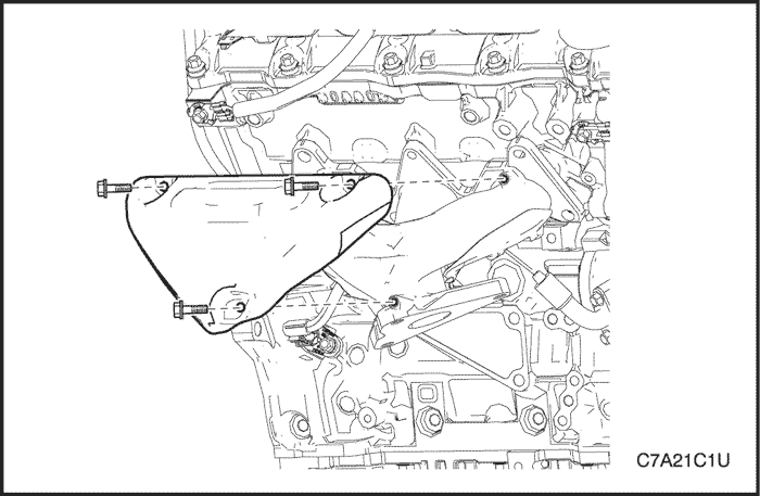
- For the bank 1 exhaust manifold, remove the transaxle rear mount assembly. Refer to "Transaxle Rear Mount Assembly"
in this section.
- Disconnect the upper heated oxygen sensor connector.
- Remove the three bolts (1) attaching the exhaust manifold outer heat shield (2) to the exhaust manifold.
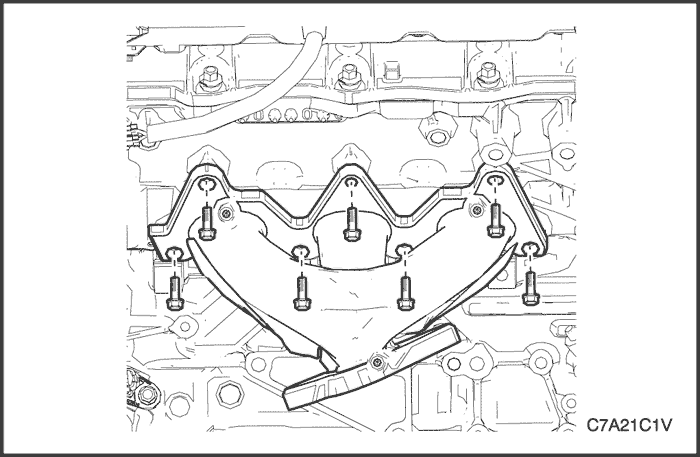
- Progressively loosen the seven exhaust manifold attaching bolts, working from the outside to the center and then remove the bolts.
- Remove and discard the exhaust manifold to cylinder head gasket.
- Remove the three bolts attaching the exhaust manifold inner heat shield from the exhaust manifold, if necessary.
Clean
- Using a suitable commercially available non-corrosive cleaning solvent and a soft bristled parts cleaning brush, thoroughly clean the exhaust manifold.
- Dry the exhaust manifold using compressed air.
Inspection
- Inspect the exhaust manifold (1) for the following:
- Damage to the threaded holes for the heat shield mounting.
- Damage to the exhaust manifold mounting holes.
- Damage to the threads of the exhaust manifold to exhaust pipe flange studs.
- Damage to the gasket sealing surfaces.
- Using a straight edge (2) and feeler gauges (3), check the cylinder head mounting face of the exhaust manifold does not exceed the maximum distortion specification of 0.25mm.
Note : If the surface flatness is not within specifications, the exhaust manifold is warped and must be replaced.
Installation Procedure
- Install the exhaust manifold inner heat shield to the exhaust manifold, if necessary.
Tighten
Tighten the exhaust manifold inner heat shield attaching bolt to 10 N•m (89 lb-in).
- Position a new exhaust manifold gasket onto the exhaust manifold.
- Apply Loctite 272 thread sealant (or equivalent) to the threads of the exhaust manifold attaching bolts.
Note : When tightening the exhaust manifold to cylinder head attaching bolts, begin with the center bolts, then alternate from side to side to the outer bolts.
- Maneuver the exhaust manifold into position and install the exhaust manifold attaching bolts.
Tighten
Tighten the Exhaust manifold to cylinder head attaching bolts to 20 N•m (15 lb-ft).
- Install the exhaust manifold heat shield.
Tighten
Tighten the exhaust manifold outer heat shield attaching bolts to 10 N•m (89 lb-in).
- Install the other parts that were previously removed.
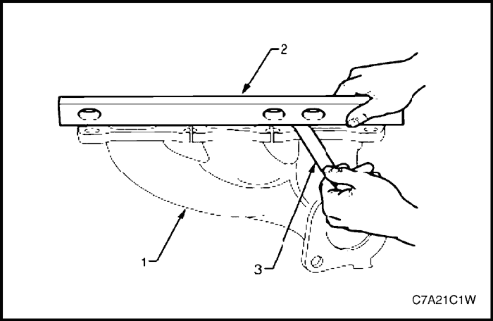
Cylinder Head Cover
Removal Procedure
- Remove the engine dress cover. Refer to "Engine Dress Cover"
in this section.
- Remove the upper intake manifold. Refer to "Upper Intake Manifold"
in this section.
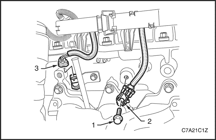
- Remove the bolt (1) attaching the ground connector (2) to the cylinder head (Bank 1 : 2 places, Bank 2 : 1 place).
- For the Bank 2, disconnect the engine coolant temperature (ECT) sensor wiring connector (3).
- Unclip the engine wiring harness retaining lugs from the side of the cylinder head covers.
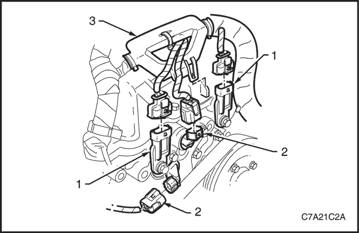
- Disconnect the camshaft position (CMP) sensor wiring connectors (1).
- Disconnect the camshaft position (CMP) actuator solenoid wiring connectors (2).
- Unclip the engine wiring harness retaining lug (3) from the front of the cylinder head cover.
- Remove the ignition coil assemblies. Refer to Section 1F3, Engine Controls - HFV6 3.2L.
- Move the engine wiring harness clear of the cylinder head covers.
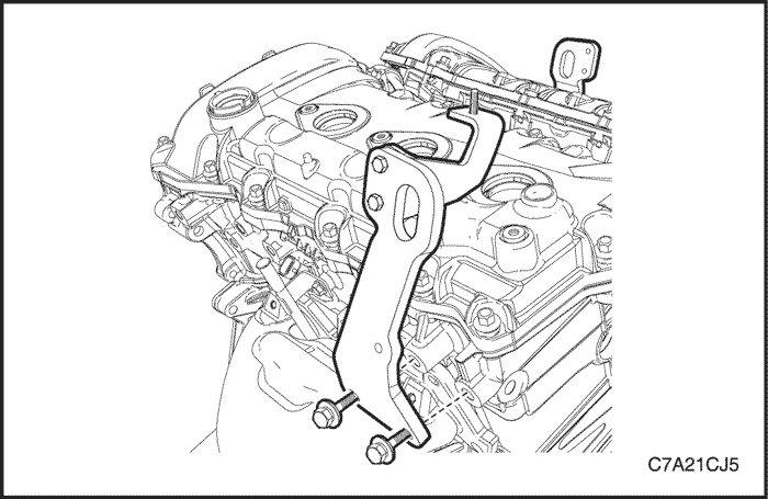
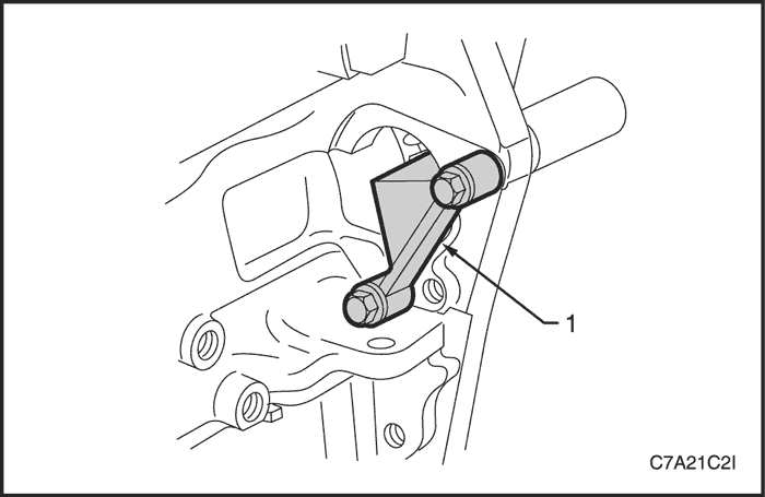
- Remove the bolt attaching the engine lift bracket from the cylinder head assembly.
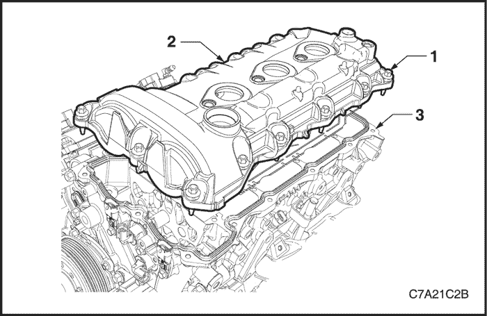
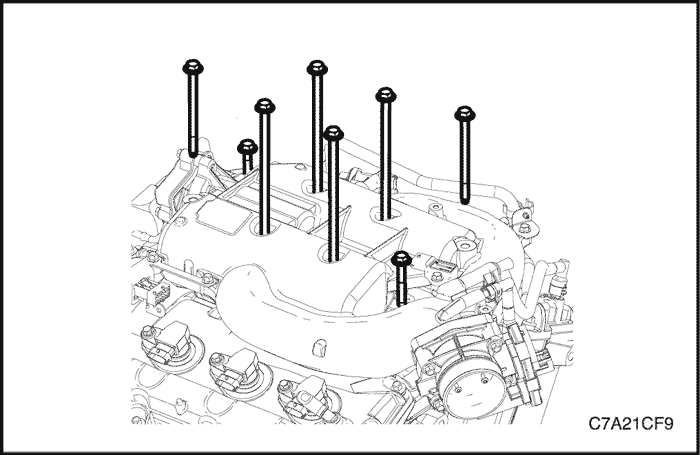
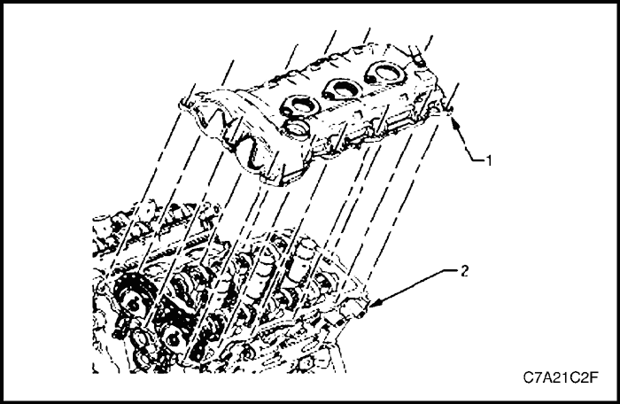
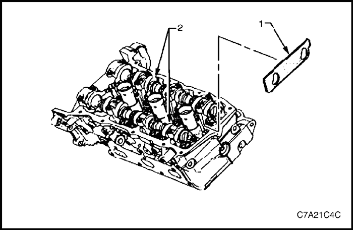
- Remove the bolt (1), 13 places, attaching the cylinder head cover (2) from the cylinder head (3).
- Remove the cover and discard the seal.
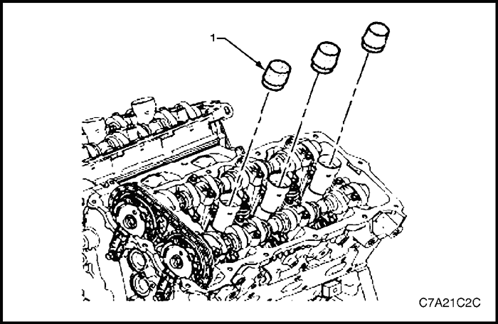
- Install Tool No. EN-46101 (1) to the spark plug tubes of the cylinder head to prevent entry of dirt into the combustion chamber.
Clean and Inspection
- Clean the cylinder head cover with suitable cleaning solvent and blow dry with compressed air.
- Inspect the cover for cracking and distortion.
- Check the spark plug tube seals for damage.
- If the cylinder head cover is damaged in any way that will affect its performance to seal and stop the ingress of dirt, replace the cylinder head cover.
Installation Procedure
- Installation should follow the removal procedure in the reverse order.
- If not already fitted, install Tool No. EN-46101 (1) to the spark plug tubes of the cylinder head.
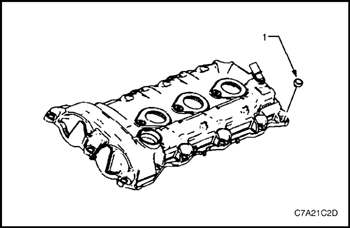
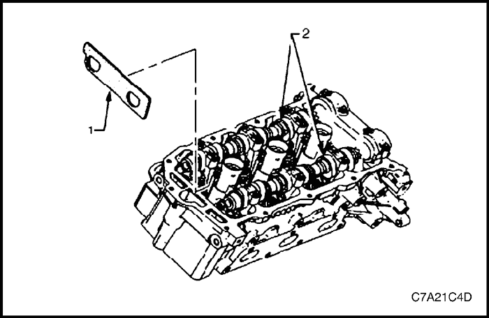
- Ensure that the grommet (1), 13 places, is correctly seated in its hole.
- Wipe the cylinder head cover sealing surface on the cylinder head with a clean lint free cloth.
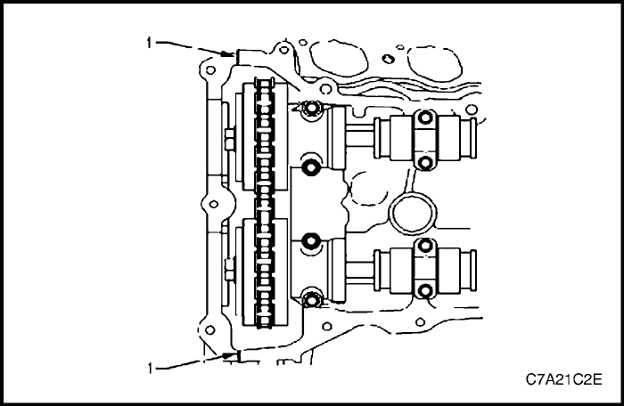
- Ensure that a new seal is correctly fitted to the cylinder head cover. Place RTV sealant on the join line of the engine front cover (1).
- Place the cylinder head cover (1) into position onto the cylinder head (2).
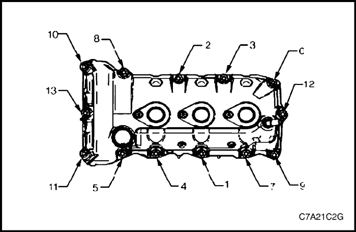
- Install the cylinder head cover bolt (1) in the sequence shown.
Tighten
Tighten the cylinder head cover attaching bolt to 10 N•m (89 lb-in).
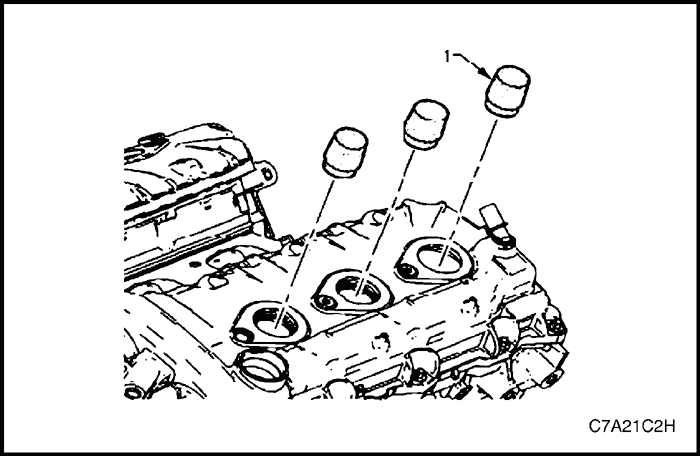
- Remove Tool No. EN-46101 (1).
- Tighten all remaining fasteners.
Tighten
-
- Tighten the engine ground connector bolt to 10 N•m (89 lb-in).
- Tighten the engine lift bracket retaining bolts to 50 N•m (37 lb-ft).
- Connect all remaining connectors.
Crankshaft Pulley
Removal Procedure
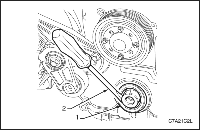
- Rotate the accessory drive belt tensioner clockwise to reduce the belt tension.
- While holding the tensioner in the reduced tension position, disconnect the belt.
- Remove the starter. Refer to Section 1E3, Engine Electrical - HFV6 3.2L.
- Install Tool No. EN-46106 (1) into the starter motor opening to stop the camshaft from rotating.
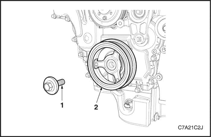
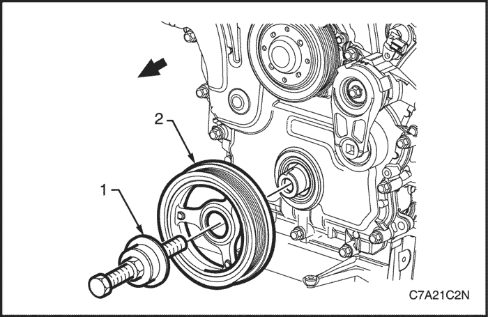
- Remove the bolt (1) attaching the crankshaft pulley assembly (2) to the crankshaft.
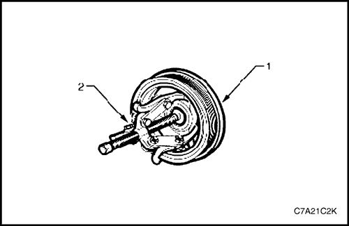
- Remove the crankshaft pulley assembly (1) from the crankshaft using three legged puller, Tool No. J-41816 (2) or equivalent.
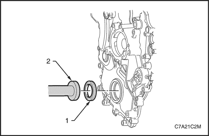
- Using a flat bladed tool (2), carefully remove the crankshaft front seal (1) from the front cover.
Clean and Inspection
- Using a suitable non-corrosive cleaning solvent and a soft bristled parts cleaning brush, clean the crankshaft pulley assembly.
- Dry the crankshaft pulley assembly using compressed air.
- Inspect the crankshaft pulley assembly for the following fault conditions:
- Hub to crankshaft inner surface for wear or damage,
- Sealing surface for wear, grooving or scoring,
- Rubber ring between the hub and the pulley for wear, chunking and general deterioration, and
- Drive belt ribs of the pulley for damage.
Installation Procedure
Caution : Do not lubricate the crankshaft front oil seal or crankshaft pulley sealing surfaces. The crankshaft pulley must be installed onto a dry seal.
- Using crankshaft front seal installer, Tool No. J-29184 (2) and a suitable hammer, install a new crankshaft front seal (1) until fully seated against the front cover housing.
- Lubricate the crankshaft pulley assembly hub bore.
- Partially install the crankshaft pulley assembly onto the crankshaft.
Caution : To prevent damage to the crankshaft threads, fully install crankshaft pulley installer, Tool No. J-41998-B (1) into the crankshaft before pressing the pulley and balancer assembly.
- Using crankshaft pulley installer, Tool No. J-41998-B (1), fully install the crankshaft pulley assembly into the crankshaft.
- Apply Loctite 272 or equivalent to the thread of a new crankshaft pulley assembly retaining bolt (1).
- Install the crankshaft pulley assembly retaining bolt.
Tighten
Tighten the crankshaft pulley assembly retaining bolt to 100 N•m (74 lb-ft) and turns the bolt another 150° using the angular torque gauge KM-470-B.
- Install the starter. Refer to Section 1E3, Engine Electrical - HFV6 3.2L.
- Install the accessory drive belt.
Front Cover Assembly
Removal Procedure
- Remove the engine assembly. Refer to "Engine Assembly"
in this section.
- Remove the cylinder head covers. Refer to "Cylinder Head Cover"
in this section.
- Remove the crankshaft pulley assembly. Refer to "Crankshaft Pulley"
in this section.
- Remove the camshaft position sensors and camshaft position actuator solenoid valves. Refer to Section 1F3, Engine Controls - HFV6 3.2L
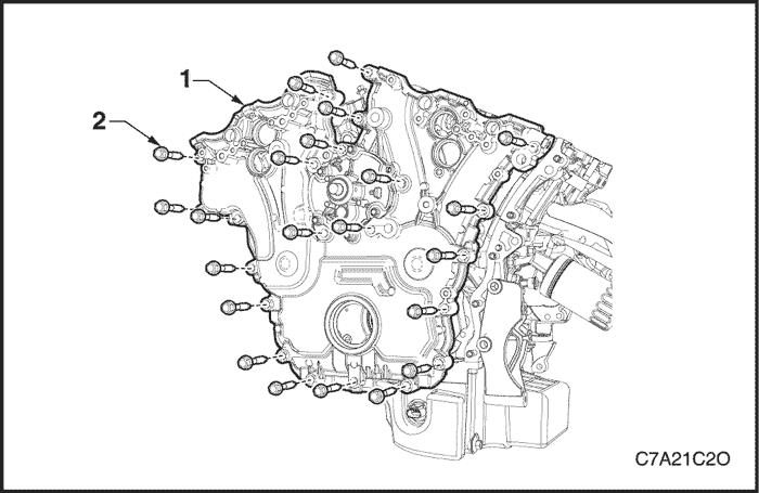
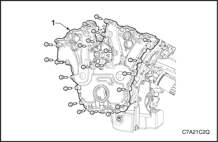
- Remove the bolt (2), 22 places, attaching the front cover assembly (1).
Caution : Only use the prise points and a bolt in the jackscrew hole to remove the engine front cover.
- Loosely install a proper bolt in the jackscrew hole (1).
- Using the prise points (2) located at the edge of the front cover and the jackscrew, shear the RTV sealant.
- Remove the front cover assembly (1).
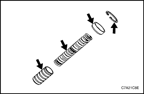
Disassembly
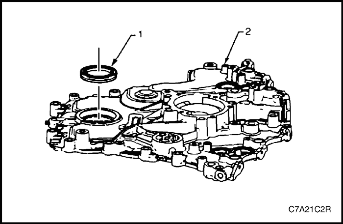
- Remove the crankshaft front oil seal (1) from the engine front cover (2) using a flat bladed tool. Discard the seals.
- Remove the camshaft position actuator valve oil seals (1) from the engine front cover (2). Discard the seals.
- Remove the coolant pump seal (1) from the engine front cover (2) and discard the seal.
Clean
Caution : Do not use a sharp or metal gasket scraper to clean the sealing surfaces.
- Remove any RTV sealant (1) from the engine front cover using a plastic or wood scraper.
- Clean out any debris from the bolt holes.
- Clean the front cover with a suitable cleaning solvent.
- Dry the front cover with compressed air.
Inspection
- Inspect both sides of the engine front cover for the following conditions:
- damage to the camshaft position actuator valve oil seal bores (1),
- damage to the bolt holes (2),
- damage and/or corrosion to the engine coolant passage (3),
- dents or damage to the exterior (4),
- damage to the crankshaft front oil seal bore (5),
- gouges or damage to the coolant pump sealing surfaces (6), and
- damage to the coolant pump bolt hole threads (7).
- Repair or replace the front cover as required.
Reassembly
Caution : Do not lubricate the crankshaft front oil seal or crankshaft pulley sealing surfaces. The crankshaft pulley is installed into a dry seal.
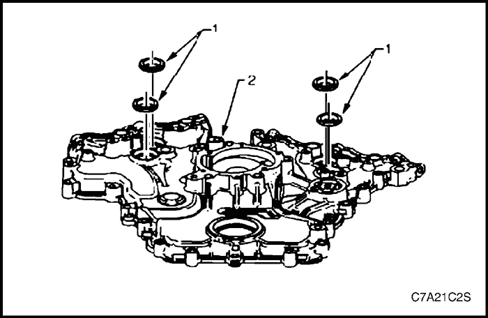
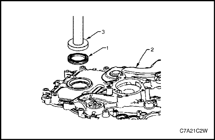
- Install a new crankshaft front oil seal (1) into the front cover (2) using crankshaft front seal installer, Tool No. J-29184 (3) and a suitable hammer.
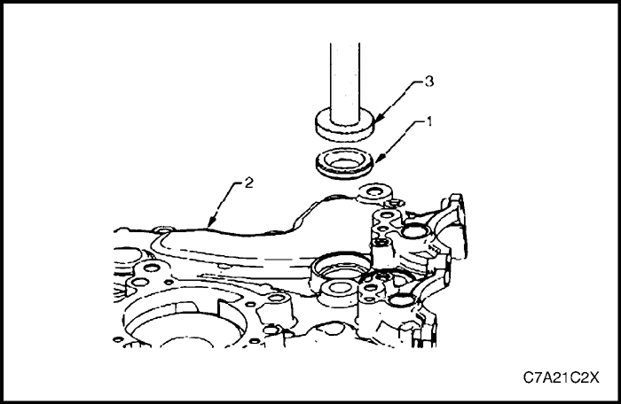
- Install a new camshaft position actuator valve oil seal (1) into the front cover (2) using Tool No. EN-46103 (3) and a suitable hammer.
Installation Procedure
- Install the guide pins, Tool No. EN-46109 (1) into the engine block, two places.

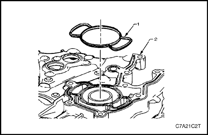
- Install a new engine front cover to cylinder block seal (1).
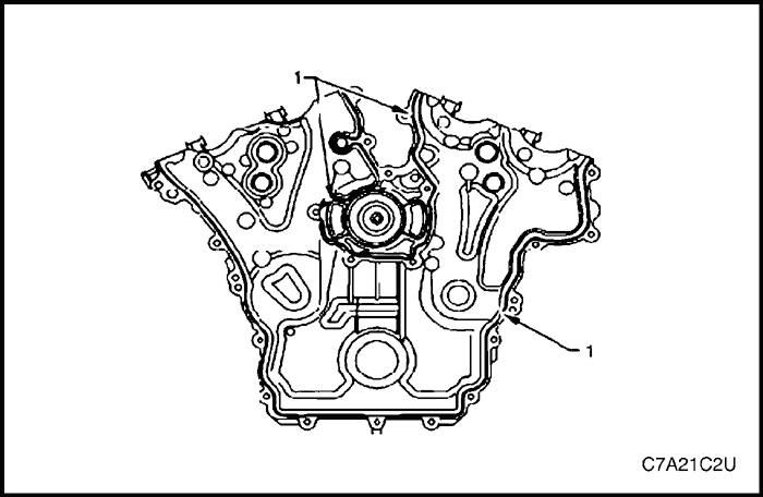
- Apply RTV sealant (1) to the front cover.
- Place the front cover onto the special tools and slide into position.
- Remove the special tools from the cylinder block.
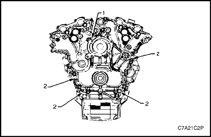
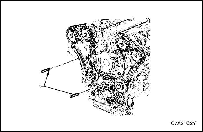
- Tighten the engine front cover bolts in the sequence shown.
Tighten
Tighten the engine front cover bolts to 23 N•m (17 lb-ft).
- Install any other parts that were previously removed.
- Install the engine assembly. Refer to "Engine Assembly"
in this section.
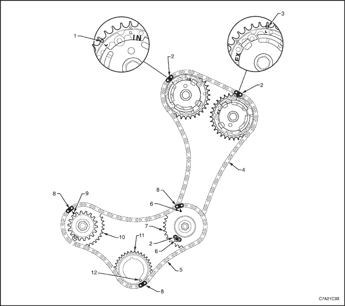
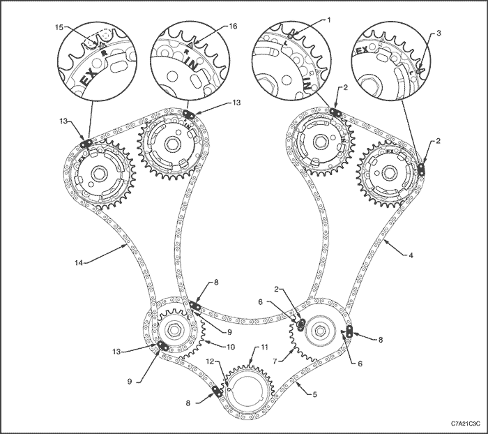
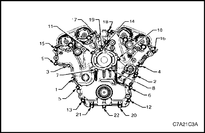
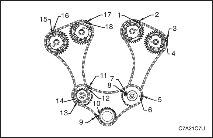
Timing Chain Components
Caution : Setting the camshaft timing is required whenever the camshaft drive system has been disturbed and the relationship between any chain and sprocket has been lost. Even when only one sprocket is involved, multiple crankshaft rotations will not produce conditions where correct timing can be confirmed. If required, follow the Bank 2 secondary timing chain reinstallation procedure to reset the camshaft timing.
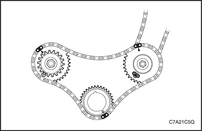
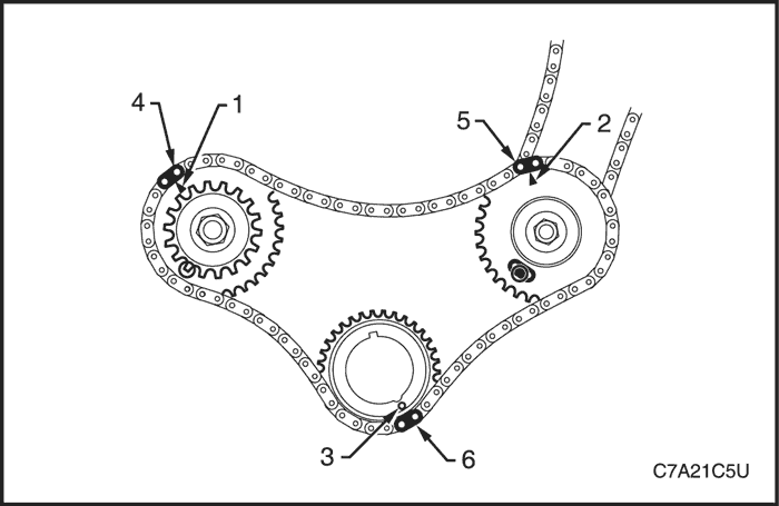
Primary and Bank 2 Secondary Timing Chain Installation
- Intake Camshaft Position (CMP) Actuator Timing Mark - Bank 2
- Secondary Timing Chain Bright Plated Link - Bank 2
- Exhaust Camshaft Position (CMP) Actuator Timing Mark - Bank 2
- Secondary Timing Chain - Bank 2
- Primary Timing Chain
- Camshaft Intermediate Driveshaft Sprocket Timing Mark - Bank 2
- Camshaft Intermediate Driveshaft Sprocket - Bank 2
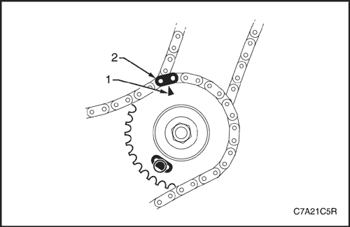
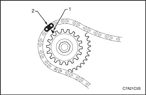
- Primary Timing Chain Bright Plated Link
- Camshaft Intermediate Driveshaft Sprocket Timing Mark - Bank 2
- Camshaft Intermediate Drive shaft Sprocket - Bank 1
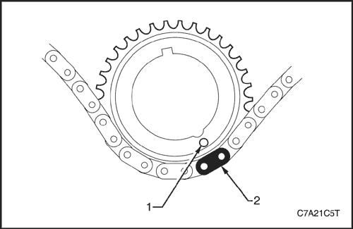
- Crankshaft Sprocket
- Crankshaft Sprocket Timing Mark
Bank 1 secondary Timing Chain Installation
- Intake Camshaft Position (CMP) Actuator Timing Mark - Bank 2
- Secondary Timing Chain Bright Plated Link - Bank 2
- Exhaust Camshaft Position (CMP) Actuator Timing Mark - Bank 2
- Secondary Timing Chain - Bank 2
- Primary Timing chain
- Camshaft Intermediate Drive Chain Sprocket Timing Mark - Bank 2
- Primary Camshaft Intermediate Drive Chain Sprocket - Bank 2
- Primary Timing Chain Bright Plated Link
- Camshaft Intermediate Drive Chain Sprocket Timing Mark - Bank 2
- Camshaft Intermediate Drive Chain Sprocket - Bank 1
- Crankshaft Sprocket
- Crankshaft Sprocket Timing Mark
- Secondary Timing chain Bright Plated Link - Bank 1
- Camshaft Intermediate Drive Chain - Bank 1
- Exhaust Camshaft Position (CMP) Actuator Timing Mark - Bank 1
- Inlet Camshaft Position (CMP) Actuator Timing Mark - Bank 1
Removal Procedure
Bank 1 Secondary Timing Chain
Caution : After removing the upper intake manifold, and spark plugs, plug any openings to prevent dirt and other contaminants from entering.
- Remove the engine front cover assembly. Refer to "Front Cover Assembly"
in this section.
- Remove the spark plugs to aid crankshaft or engine rotation.
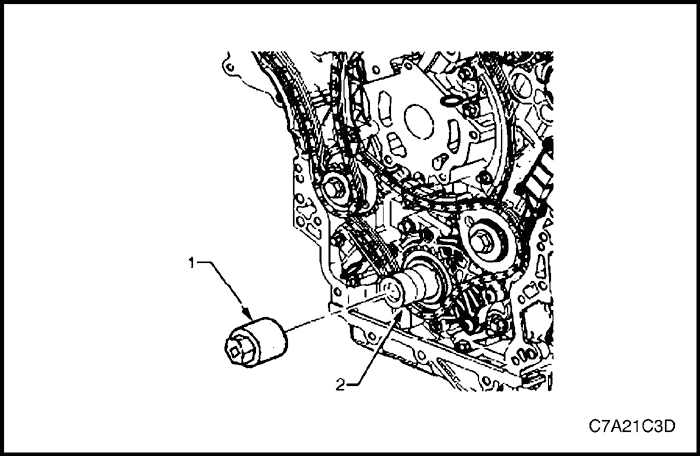
- Install Tool No. EN46111 (1) onto the crankshaft (2).
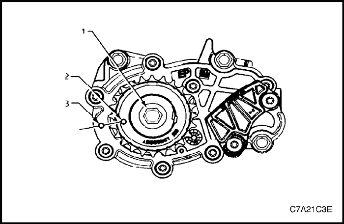
- Using Tool No. EN46111 (1), rotate the crankshaft in a clockwise direction until the crankshaft sprocket timing mark (2) is aligned with the indexing mark (3) on the oil pump housing.
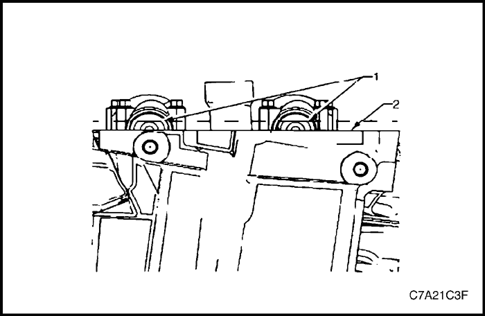
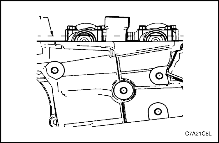
- After aligning the crankshaft sprocket timing mark, check that the camshaft flats (1) at the rear of the Bank 1 cylinder head are parallel with the cylinder head cover rail (2).
- If the camshaft flats are not as shown, rotate the crankshaft 360°.
- Install Tool No. EN 46105-1 (1) onto the rear of the Bank 1 cylinder head camshafts (2).
- Install Tool No. EN 46105-2 (1) onto the rear of the Bank 2 cylinder head camshafts (2).
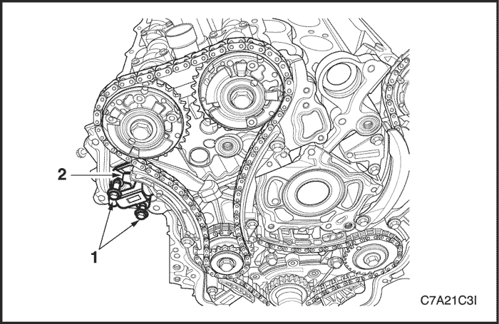
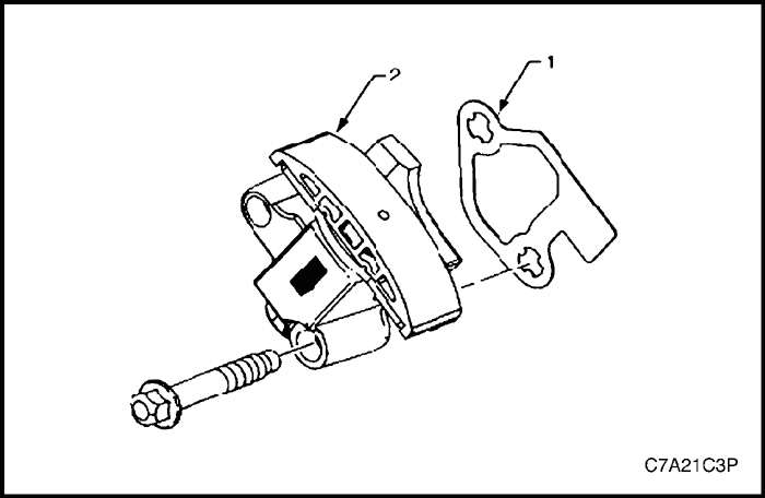
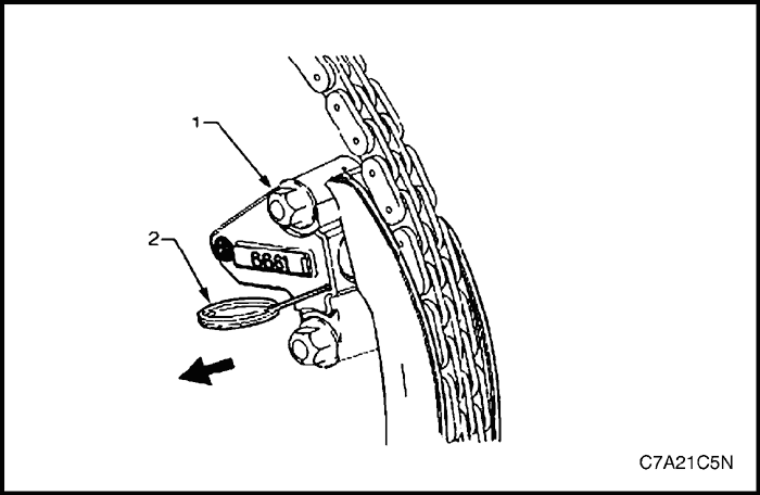
- Remove the Bank 1 secondary timing chain tensioner bolts (1) and remove the tensioner (2).
Note : Take care when removing the tensioner bolts. The tensioner plunger is subjected to spring tension and may spring apart during tensioner removal.
- Remove the tensioner gasket (1) from the tensioner (2) and discard the gasket.
- Inspect the tensioner mounting surface on the Bank 1 cylinder head for burrs or any defects that would affect the sealing of a new tensioner gasket.
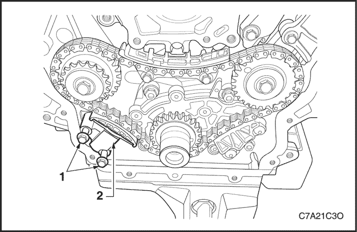
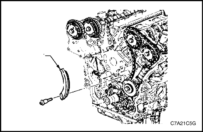
- Remove the Bank 1 secondary timing chain shoe bolt (1).
- Remove the Bank 1 secondary timing chain shoe (1).
- Remove the two Bank 1 secondary timing chain guide bolts (1) and remove the guide (2).
- Remove the Bank 1 secondary timing chain (1) from the camshaft position actuators (2) and the camshaft intermediate driveshaft sprocket (3).
Primary Timing Chain
- Remove the Bank 1 secondary timing chain. Refer to "Timing Chain Components"
in this section.
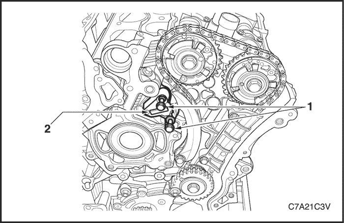
- Remove the two primary timing chain tensioner bolts (1), and remove the tensioner (2).
Note : Take care when removing the tensioner bolts. The tensioner plunger is subjected to spring tension and may spring apart during tensioner removal.
- Remove the gasket (1) from the tensioner (2) and discard the gasket.
- Inspect the primary timing chain tensioner mounting surface on the engine block for burrs or any defects that would affect the sealing of a new tensioner gasket.
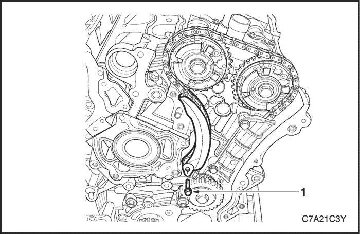
- Remove the two primary timing chain upper guide bolts (1) and remove the guide (2).
Note : Do not remove the primary timing chain lower guide (1). The primary timing chain lower guide is not serviced separately. If the primary timing chain lower guide requires replacement, the oil pump assembly (2) must be replaced.
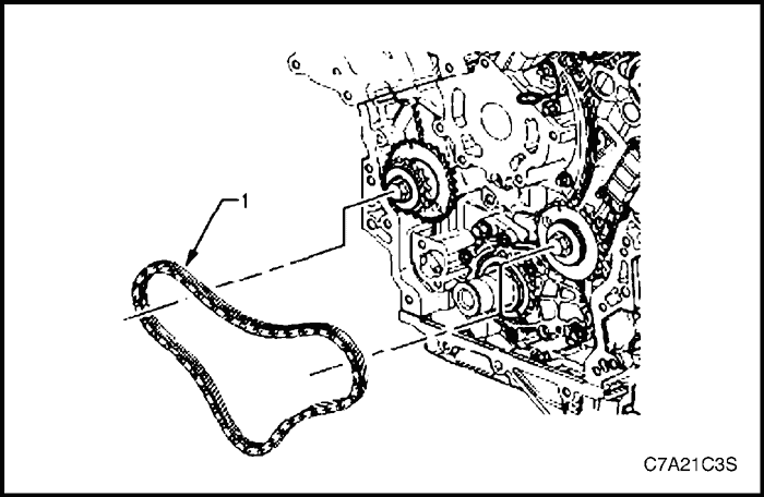
- Remove the primary timing chain (1).
Note : For ease of removal, remove the chain from the crankshaft sprocket, before attempting to remove from the camshaft intermediate driveshaft sprockets.
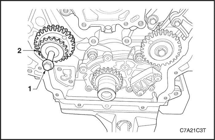
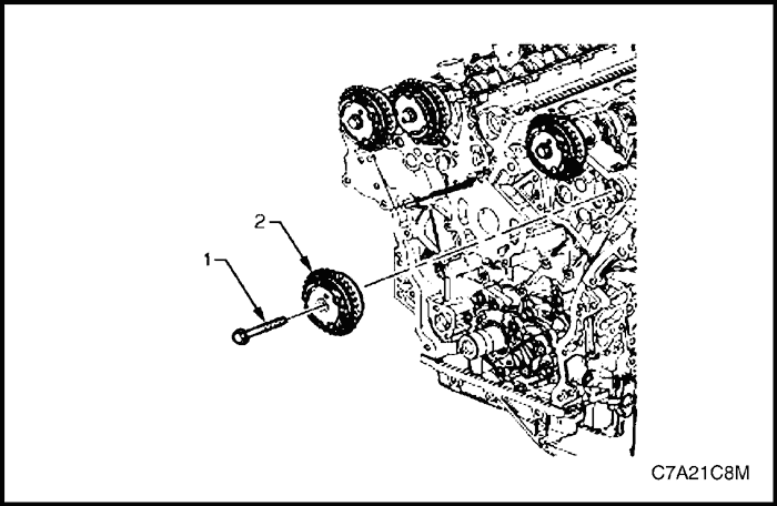
- If required, remove the Bank 1 camshaft intermediate driveshaft sprocket bolt (1) and remove the sprocket (2).
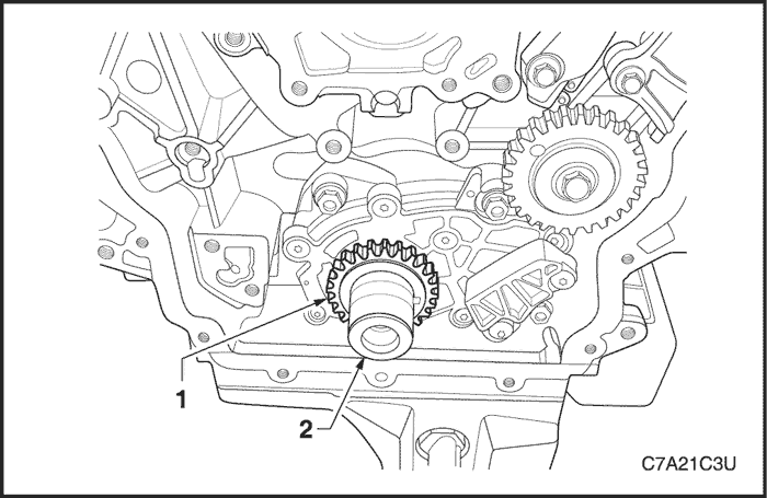
- If required, remove the crankshaft sprocket (1) from the crankshaft (2).
Bank 2 Secondary Timing Chain
- Remove the primary timing chain. Refer to "Timing Chain Components"
in this section.
- Remove the two Bank 2 secondary timing chain tensioner bolts (1) and remove the tensioner (2).
Note : Take care when removing the tensioner bolts. The tensioner plunger is subjected to spring tension and may spring apart during tensioner removal.
- Remove the gasket (1) from the tensioner (2) and discard the gasket.
- Inspect the tensioner mounting surface on the Bank 2 cylinder head for burrs or any defects that would affect the sealing of a new tensioner gasket.
- Remove the Bank 2 secondary timing chain shoe bolt (1).
- Remove the Bank 2 secondary timing chain shoe (1).
- Remove the Bank 2 secondary timing chain guide bolt (1), two places, and remove the guide (2).
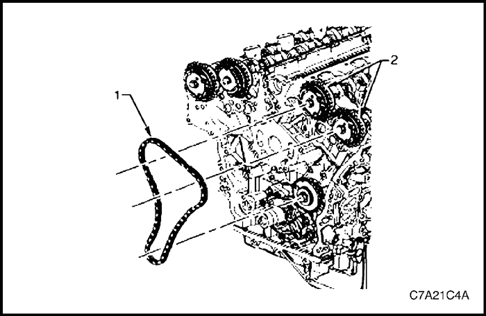
- Remove the Bank 2 secondary timing chain (1) from the camshaft position actuators (2) and the camshaft intermediate driveshaft sprocket.
- If required, remove the Bank 2 camshaft intermediate driveshaft sprocket bolt (1) and remove the sprocket (2).
- Remove Tool No. EN 46105-2 (1) from the Bank 2 cylinder head camshafts (2).
- Remove Tool No. EN 46105-1 (1) from the Bank 1 cylinder head camshafts (2).
Clean
- Clean all the following components with a suitable solvent:
- crankshaft sprocket,
- primary timing chain,
- primary timing chain guide,
- primary timing chain tensioner,
- secondary timing chains,
- secondary timing chain shoes,
- secondary timing chain guides,
- secondary timing chain tensioners, and
- bolts.
- Dry all the components with compressed air.
Inspection
Timing Chains
- Inspect the primary and/or secondary timing chains for the following:
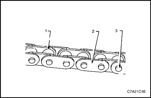
- binding or worn rollers (1),
- loose links (2), and
- loose pins (3).
- Replace a damaged timing chain as required.
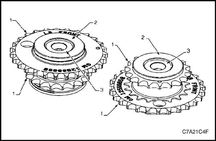
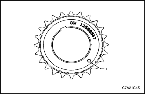
Camshaft Intermediate Driveshaft Sprockets
- Inspect the camshaft intermediate driveshaft sprockets for the following:
- Damage to the primary and secondary timing chain sprocket (1).
- Damage to the hub bearing (2). Ensure the hub bearing spins freely. If the hub bearing wobbles, is noisy or feels rough when rotated replace the camshaft intermediate sprocket, and
- Damage to the bolt flange seating / sealing surface (3).
- Damage to the bearing hub-to-engine block sealing surface.
- Inspect the camshaft position actuator assemblies. Refer to "Camshaft Position Actuator Assembly"
in this section.
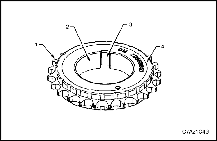
Crankshaft Sprockets
- Inspect the crankshaft sprocket for the following:
- sprocket damage (1),
- bore damage (2),
- keyway damage (3), and
- damage to the cushion material (4).
- Replace a damaged sprocket as required.
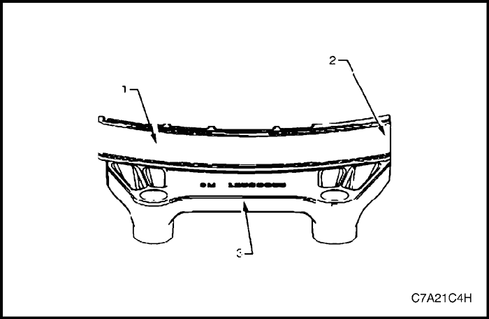
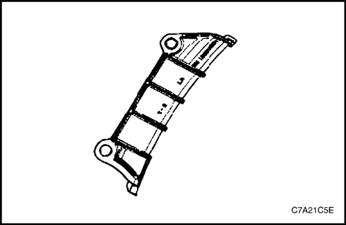
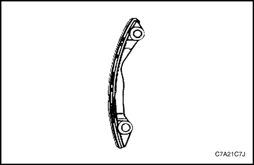
Primary Timing Chain Upper Guide
- Inspect the primary timing chain lower guide for the following:
- worn guide surface (1),
- cracked or broken guide surface (2), and
- cracked or damaged guide base (3).
- Replace a damaged guide as required.
Primary Timing Chain Lower Guide
- Inspect the primary timing chain lower guide for the following:
- worn guide surface (1),
- cracked or broken guide surface (2), and
- cracked or damaged guide base (3).
Note : The primary timing chain lower guide is not serviced separately and is part of the oil pump assembly.
- Replace the primary timing chain lower guide by replacing the oil pump assembly. Refer to "Oil Pump Assembly"
in this section.
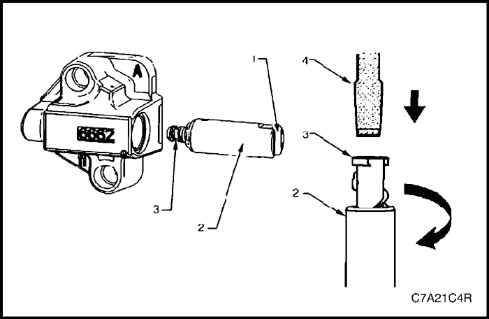
Primary Timing Chain Tensioner
- Inspect the primary timing chain tensioner for worn shoe surface (1).
- Inspect the tensioner for a locked or binding tensioner shaft (2). Reset the plunger (3) and ensure the tensioner shaft moves freely in and out of the body of the tensioner.
Note : To reset the tensioner, use a suitably sized flat blade screwdriver (4) to wind the plunger in a clockwise direction, into the tensioner shaft.
- Replace a damaged tensioner as required.
Bank 2 Secondary Timing Chain Guide
- Inspect the bank 2 secondary timing chain guide for the following:
- worn guide surface (1),
- cracked or broken guide surface (2), and
- cracked or damaged guide base (3).
- Replace a damaged guide as required.Reset the plunger (3) and ensure the tensioner shaft moves freely in and out of the body of the tensioner.
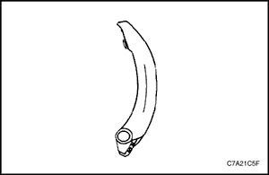
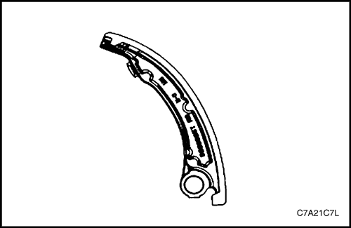
Bank 2 Secondary Timing Chain Shoe
- Inspect the front of the bank 2 secondary timing chain shoe for the following:
- worn shoe surface (1),
- cracked or broken shoe surface (2), and
- cracked or damaged shoe (3).

- Inspect the back of the shoe for a damaged, worn or missing timing chain tensioner contact pad (1).
- Replace a damaged shoe as required.
Bank 2 Secondary Timing Chain Tensioner
- Inspect the bank 2 secondary timing chain tensioner for damaged plunger-to-shoe contact surface (1).
- Inspect the tensioner for locked or binding tensioner shaft (2). Reset the plunger (3) and ensure the tensioner shaft moves freely in and out of the body of the tensioner.
Note : To reset the tensioner, use a suitably sized flat blade screwdriver (4) to wind the plunger in a clockwise direction, into the tensioner shaft.
- Replace a damaged tensioner as required.
Bank 1 Secondary Timing Chain Guide
- Inspect the bank 1 secondary timing chain guide for the following:
- worn guide surface (1),
- cracked or broken guide surface (2), and
- cracked or damaged guide base (3).
- Replace a damaged guide as required.
Bank 1 Secondary Timing Chain Shoe
- Inspect the front of the bank 1 secondary timing chain shoe for the following:
- worn shoe surface (1),
- cracked or broken shoe surface (2), and
- cracked or damaged shoe (3).
- Inspect the back of the shoe for a damaged, worn or missing timing chain tensioner contact pad (1).
- Replace a damaged shoe as required.
Bank 1 Secondary Timing Chain Tensioner
- Inspect the bank 1 secondary timing chain tensioner for damaged plunger-to-shoe contact surface (1).
Note : To reset the tensioner, use a suitably sized flat blade screwdriver (4) to wind the plunger in a clockwise direction, into the tensioner shaft.
- Inspect the tensioner for a locked or binding tensioner shaft (2). Reset the plunger (3) and ensure the tensioner shaft moves freely in and out of the body of the tensioner.
- Replace a damaged tensioner as required.
Installation Procedure
Bank 2 Timing Chain Components
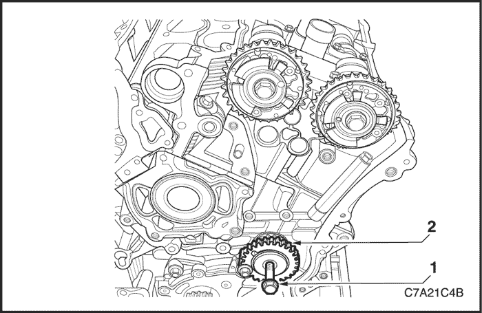
- Install the crankshaft sprocket (1) onto the crankshaft (2) by aligning the keyway to the key on the crankshaft.
- Slide the crankshaft sprocket on the crankshaft until the crankshaft sprocket contacts the step in the crankshaft.
Note : Ensure that the crankshaft sprocket is installed with the timing mark (1) visible.
Caution : In order to install Tool No. EN 46105 onto the camshafts, rotate the camshafts in an anti-clockwise direction. There should be no need to rotate the camshaft more than 45 degrees.
- Install Tool No. EN 46105-1 (1) onto the rear of the bank 2 cylinder head camshafts (2), and Tool No. EN 46105-2 onto the rear of the bank 1 cylinder head camshafts.
Caution : All camshafts must be locked in place before installation of any timing chains.
- Ensure that Tool No. EN 46105 is fully seated onto the camshafts.
- Using Tool No. EN46111 (1), rotate the crankshaft in a clockwise direction until the crankshaft sprocket timing mark (2) is aligned with the indexing mark (3) on the oil pump housing.
- Install the bank 2 secondary timing chain (1) aligning the chain in the following manner:
-
- A. Wrap the secondary timing chain around both bank 2 actuator drive sprockets.
- B. Ensure there are two bright links located on top of each of the camshaft actuator sprockets.
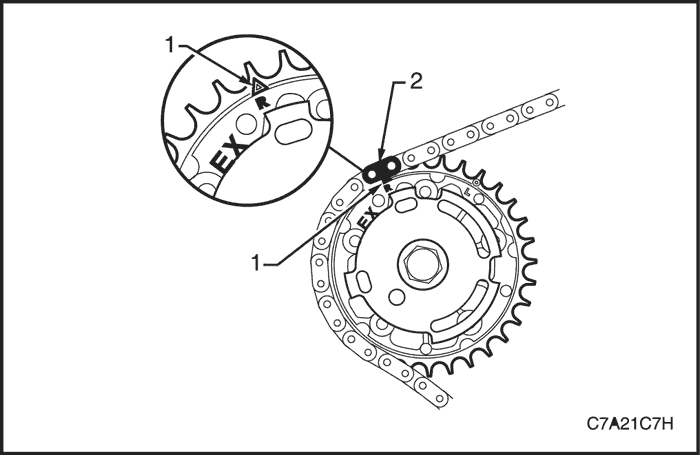
Caution : When aligning the bank 2 secondary timing chain to the camshaft actuator sprockets, ensure the circular timing marks on the sprocket are used, NOT the triangular mark.
-
- C. Align the bright plated timing chain link (1) with the bank 2 exhaust camshaft position actuator sprocket alignment circle mark (2).
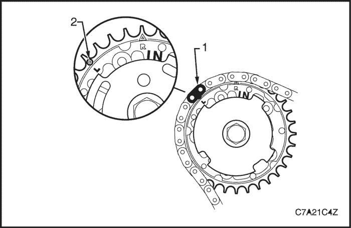
-
- D. Align the bright plated timing chain link (1) with the intake camshaft position actuator sprocket alignment circle mark (2).
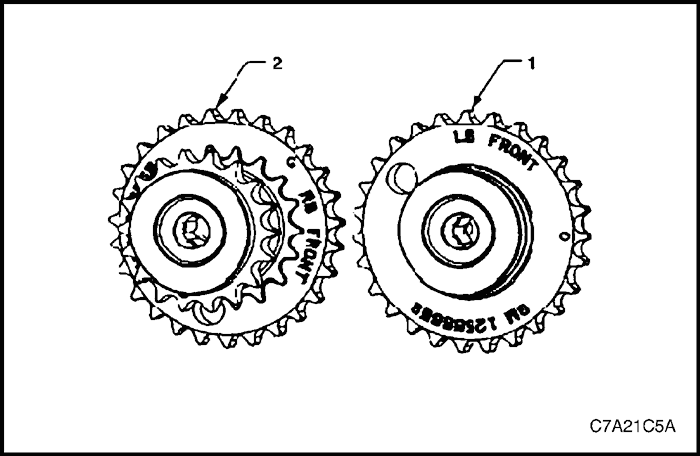
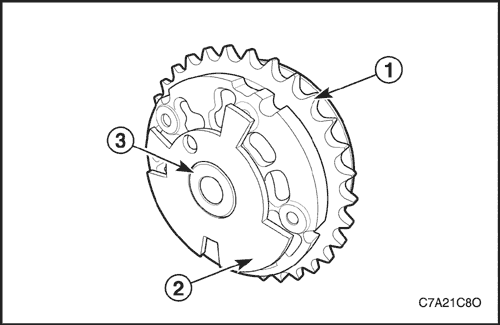
Caution : The bank 2 camshaft intermediate driveshaft sprocket (1) is marked with the letters LB and 'FRONT', and the bank 1 sprocket (2) is marked with the letters RB and 'FRONT' Ensure the correct sprocket is used and the 'FRONT' text is facing forwards when installed.
- Ensure the bank 2 camshaft intermediate driveshaft sprocket is selected and orientated correctly.
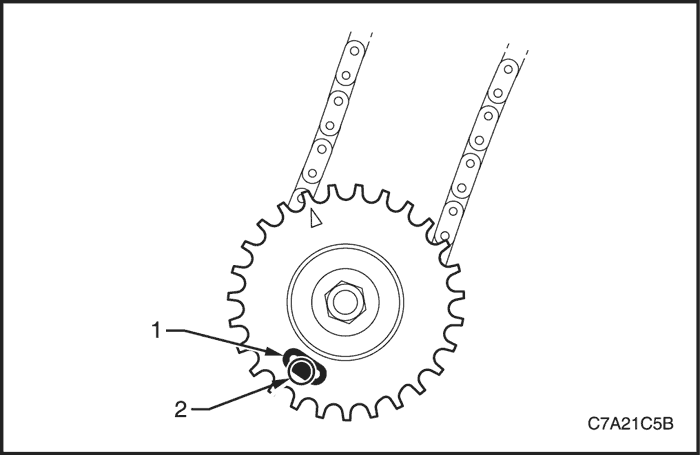
- Place the bank 2 secondary timing chain around the left-hand camshaft intermediate driveshaft inner sprocket, with the bright plated timing chain link (1) aligned with the access hole (2) in the outer sprocket.
- Install the bank 2 camshaft intermediate driveshaft sprocket to the cylinder block.
Tighten
Tighten the camshaft intermediate driveshaft sprocket attaching bolt to 66 N•m (49 lb-ft).
- Verify the Bank 2 secondary timing chain timing mark alignments (1 to 6).
Caution : The bank 2 secondary timing chain guide is marked with the letters LH. Ensure the correct shoe is used when installing to the Bank 2 side in this procedure and that the letters 'LH" are facing the front of the vehicle when installed.
- Ensure the bank 2 secondary timing chain guide is selected and orientated correctly.
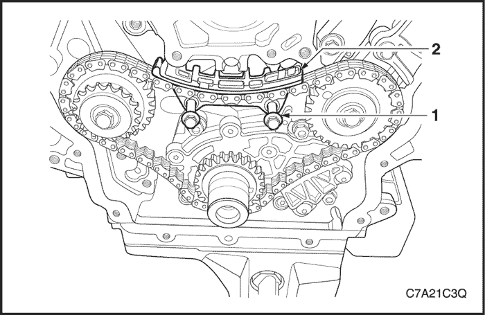
- Install the bank 2 secondary timing chain guide (1).
Tighten
Tighten the secondary timing chain guide attaching bolt to 23 N•m (17 lb-ft).
Caution : The bank 2 secondary timing chain shoe (2) is marked with the letters LH on the back face of the timing chain shoe. Ensure the correct shoe is used when installing to the bank 2 side.
- Ensure the bank 2 secondary timing chain shoe is selected and orientated correctly.
- Install the bank 2 secondary timing chain shoe (1).
Note : Ensure secondary timing chain shoe is clear of the Bank 2 secondary timing chain tensioner mounting pad, before tightening the attaching bolt.
Tighten
Tighten the bank 2 secondary timing chain shoe bolt to 23 N•m (17 lb-ft).
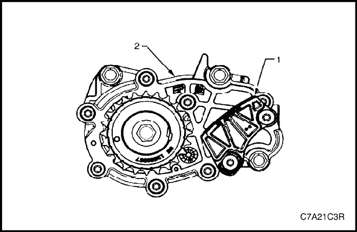
- Ensure the bank 2 secondary timing chain tensioner is selected and orientated correctly.
- Reset the bank 2 secondary timing chain tensioner.
Note : To reset the tensioner, use a suitably sized flat blade screwdriver (1) to wind the plunger in a clockwise direction, into the tensioner shaft (2).
- Install the tensioner shaft (1) into the bank 2 secondary timing chain tensioner body (2).
Caution : If Tool No. EN 46112 (1) is not inserted into the tensioner body (2), the tensioner shaft (3) will remain in the locked position and no tension will be placed on the timing chain, this will cause damage to the engine.
- Compress the tensioner shaft into the body and lock the bank 2 secondary timing chain tensioner by inserting Tool No. EN 46112 into the access hole in the side of the tensioner body.
- Slowly release pressure on the bank 2 secondary timing chain tensioner. The tensioner should remain compressed.
- Install a new bank 2 secondary timing chain tensioner gasket (1) to the tensioner (2).
- Install the bank 2 secondary timing chain tensioner bolts through tensioner and gasket.
- Ensure the bank 2 secondary timing chain tensioner mounting surface on the Bank 2 cylinder head does not have any burrs or defects that would affect the sealing of the new gasket.
- Place the bank 2 secondary timing chain tensioner (2) into position and loosely install the bolts (1) to the cylinder head.
- Verify the proper placement of the bank 2 secondary timing chain tensioner gasket tab (1).
- Tighten the bank 2 secondary timing chain tensioner bolts (2).
Tighten
Tighten the bank 2 secondary timing chain tensioner bolts to 23 N•m (17 lb-ft).
- Release the bank 2 secondary timing chain tensioner (1) by pulling out Tools No. EN 46112 (2) and unlocking the tensioner shaft.

- Verify the bank 2 secondary timing chain timing mark alignments (1 to 6).
Primary Timing Chain Components
- If previously removed, install the bank 2 secondary timing chain components. Refer to "Timing Chain Components"
in this section.
Caution : The bank 1 camshaft intermediate driveshaft sprocket (2) is marked with the letters RB and 'FRONT', and the bank 2 sprocket (1) is marked with the letters LB and 'FRONT' Ensure the correct sprocket is used and the FRONT text is facing forwards when installed.
- Ensure the bank 1 camshaft intermediate driveshaft sprocket is selected and orientated correctly.
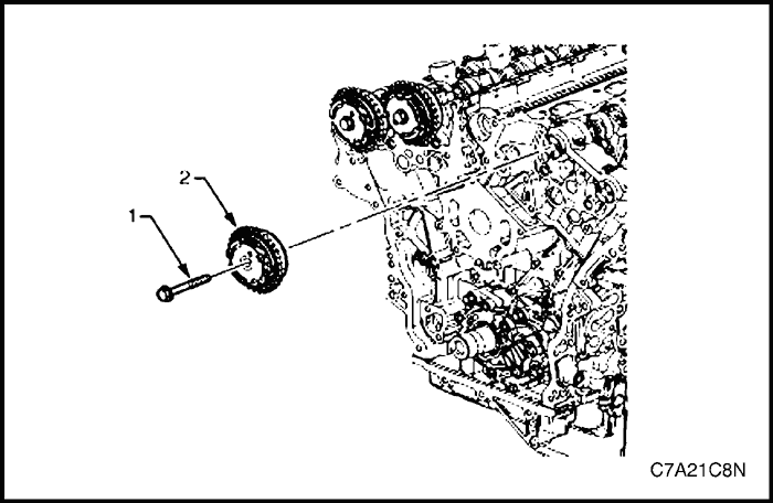
- Install the bank 1 camshaft intermediate driveshaft sprocket (2).
Tighten
Tighten the bank 1 camshaft intermediate driveshaft sprocket attaching bolt to 65 N•m (48 lb-ft).

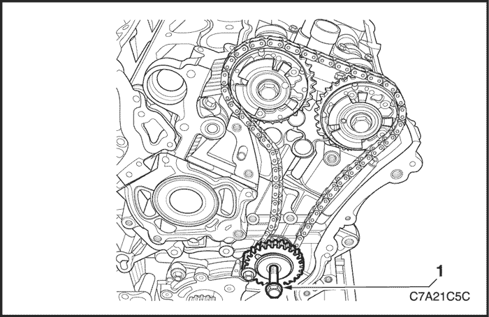
- Ensure that the crankshaft sprocket timing mark (1) is aligned with the indexing mark (2) on the oil pump housing.
- Install the primary timing chain (1).
- Wrap the primary timing chain around the large sprockets of each camshaft intermediate driveshaft sprocket and the crankshaft sprocket aligning the brightened chain links as follows:
-
- A. The bank 2 camshaft intermediate driveshaft sprocket timing mark (1) will align with a bright plated primary timing chain link (2).
-
- B. The bank 1 camshaft intermediate driveshaft sprocket timing mark (1) will align with a bright plated primary timing chain link (2).
-
- C. The crankshaft sprocket timing mark (1) will align with a bright plated timing chain link (2).
- Ensure all the timing marks (1, 2 and 3) are properly aligned with the bright plated timing chain links (4, 5 and 6).
Note : Do not remove the primary timing chain lower guide (1). The primary timing chain lower guide is not serviced separately. If the primary timing chain lower guide must be replaced, the oil pump assembly (2) must be replaced.
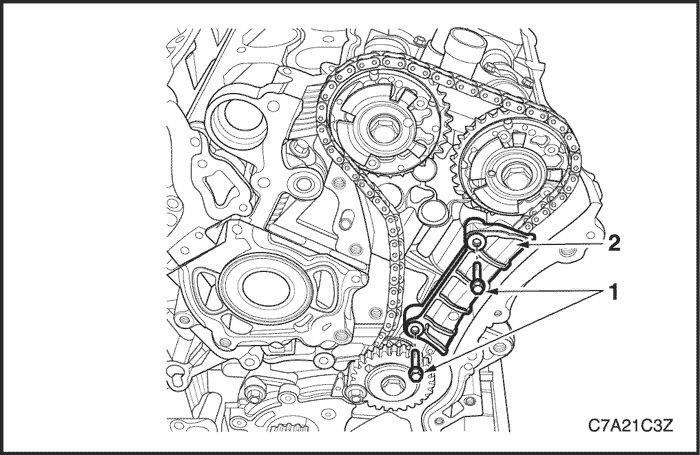
- Ensure the primary timing chain upper guide is selected and orientated correctly.
- Install the primary timing chain upper guide (1).
- Install the primary timing chain upper guide bolts (2).
Tighten
Tighten the primary timing chain upper guide bolts to 23 N•m (17 lb-ft).
- Ensure that the primary timing chain tensioner is being installed.
- Reset the primary timing chain tensioner.
Note : To reset the tensioner, use a suitably sized flat blade screwdriver (1) to wind the plunger in a clockwise direction, into the tensioner shaft (2).
- Install the tensioner shoe assembly (1) into the primary timing chain tensioner body (2).
Caution : If Tool No. EN 46112 (1) is not inserted into the tensioner body, the plunger will remain in the locked position and no tension will be placed on the timing chain.
- Compress the shoe assembly into the body (2) and lock the primary timing chain tensioner by inserting Tool No. EN 46112 into the access hole in the side of the body.
- Slowly release pressure on the primary timing chain tensioner. The primary timing chain tensioner should remain compressed.
- Install a new primary timing chain tensioner gasket (1) to the tensioner (2).
- Install the primary timing chain tensioner bolts (3) through tensioner and gasket.
- Ensure the primary timing chain tensioner mounting surface on the engine block does not have any burrs or defects that would affect the sealing of the new gasket.
- Place the primary timing chain tensioner (2) into position and loosely install the bolts (1) to the engine block.
- Verify the proper placement of the primary timing chain tensioner gasket tab (1).
- Tighten the primary timing chain tensioner bolts (2).
Tighten
Tighten the primary timing chain tensioner bolts to 23 N•m (17 lb-ft).
- Release the primary timing chain tensioner (1) by pulling out Tool No. EN 46112 (2) and unlocking the tensioner shaft.
- Verify the primary and bank 2 secondary timing chain timing mark alignments (1 to 12).
- Remove Tool No. EN 46105 from the bank 2 and bank 1 cylinder head camshafts.
Bank 1 Secondary Timing Chain Components
- Install the primary timing chain components. Refer to "Timing Chain Components"
in this section.
- Using Tool No. EN46111 (1), rotate the crankshaft in a clockwise direction until the crankshaft sprocket timing mark (2) is aligned with the indexing mark (3) on the oil pump housing.
Caution : In order to install Tool No. EN 46105 onto the camshafts, rotate the camshafts. There should be no need to rotate the camshaft more than 45 degrees.
- Install Tool No. EN 46105-1 (1) onto the rear of the bank 1 cylinder head camshafts (2).
- Install Tool No. EN 46105-2 (1) onto the rear of the bank 2 cylinder head camshafts (2).
- Install the bank 1 secondary timing chain (1) onto the camshaft actuators (2) and the right hand camshaft intermediate driveshaft sprocket (3) aligning the chain in the following manner:
-
- A. Place the secondary timing chain around the bank 1 camshaft intermediate driveshaft outer sprocket, aligning the bright plated timing chain link (1) with the alignment access hole (2) in the inner sprocket.
-
- B. Wrap the secondary timing chain around both bank 1 actuator drive sprockets.
Caution : Ensure that when aligning the bank 1 secondary timing chain to the bank 1 camshaft actuator sprockets, that the triangular timing marks (1) on the sprocket are used, NOT the circular mark.
-
- C. Align the bright plated timing chain link (2) with the exhaust actuator sprocket alignment triangle mark.
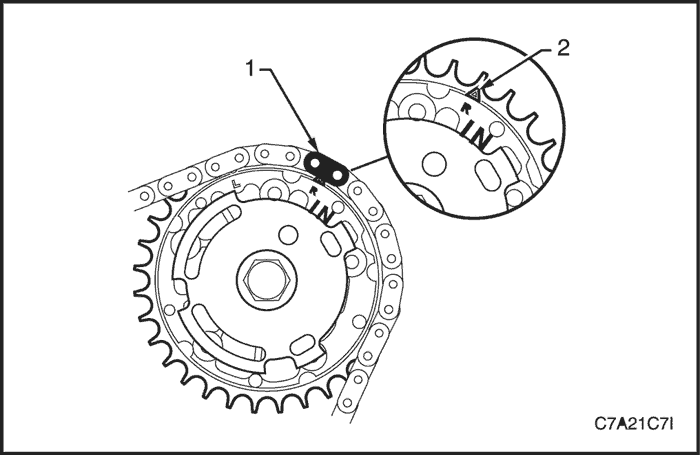
-
- D. Align the bright plated timing chain link (1) with the intake actuator sprocket alignment triangle mark (2).
Caution : Ensure that the bank 1 secondary timing chain guide is used when installing to the Bank 1 side in this procedure.
- Ensure that the bank 1 secondary timing chain guide is selected and orientated correctly.
- Position the chain guide (2).
- Ensure the primary timing chain upper guide is selected and orientated correctly.
Tighten
Tighten the secondary timing chain guide bolts to 23 N•m (17 lb-ft).
Caution : The bank 1 secondary camshaft drive shoe is marked with the letters 'RH'. Ensure that the bank 1 drive shoe is used when installing to the bank 1 side in this procedure and that the letters 'RH" are facing the front of the vehicle when installed.
- Ensure the bank 1 secondary timing chain shoe is selected and orientated correctly.
- Position the bank 1 secondary timing chain shoe (1).
Tighten
Tighten the bank 1 secondary timing chain shoe attaching bolt to 23 N•m (17 lb-ft).
- Ensure the bank 1 secondary timing chain tensioner is selected and orientated correctly.
- Reset the bank 1 secondary timing chain tensioner.
Note : To reset the tensioner, use a suitably sized flat blade screwdriver (1) to wind the plunger in a clockwise direction, into the tensioner shaft (2).
- Install the tensioner shaft (1) into the bank 1 secondary timing chain tensioner body (2).
Caution : If Tool No. EN 46112 (1) is not inserted into the tensioner body (2), the plunger will remain in the locked position and no tension will be placed on the timing chain, this will cause damage to the engine.
- Compress the tensioner shaft into the body and lock the tensioner by inserting Tool No. EN 46112 into the access hole in the side of the tensioner body.
- Slowly release pressure on the bank 1 secondary timing chain tensioner. The tensioner should remain compressed.
- Install a new bank 1 secondary timing chain tensioner gasket (1) to the tensioner (2).
- Install the bank 1 secondary timing chain tensioner bolts (3) through the tensioner and gasket.
- Ensure the bank 1 secondary timing chain tensioner mounting surface on the bank 1 cylinder head does not have any burrs or defects that would affect the sealing of the new tensioner gasket.
- Place the bank 1 secondary timing chain tensioner (2) into position and loosely install the bolts (1) to the engine block.
- Verify the proper placement of the bank 1 secondary timing chain tensioner gasket tab (1).
- Tighten the bank 1 secondary timing chain tensioner bolts (2).
Tighten
Tighten the bank 1 secondary timing chain tensioner bolts to 23 N•m (17 lb-ft).
- Release the bank 1 timing chain tensioner (1) by pulling out Tool No. EN 46112 (2) and unlocking the tensioner plunger.
- Verify all primary and secondary timing chain timing mark alignments (1 to 18).
- Remove Tool No. EN 46105 and EN 46105-2 from the both cylinder head camshafts.
- Reinstall the spark plugs. Refer to Section 1F3, Engine Controls - HFV6 3.2L.
- Reinstall the engine front cover assembly. Refer to "Front Cover Assembly"
in this section.
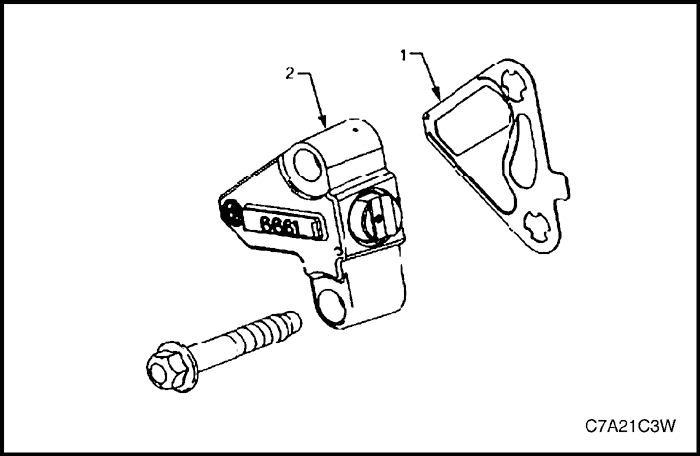
Oil Pump Assembly
Removal Procedure
- Remove the primary timing chain and crankshaft sprocket. Refer to "Timing Chain Components"
in this section.
- Remove the three bolts (1) attaching the oil pump (2).
- Remove the oil pump assembly.
Disassembly
Caution :
-
- There are no serviceable components within the oil pump. Disassemble the pump only to diagnose oil related concern. A disassembled oil pump must not be reused: it must be replaced.
- The primary timing chain lower guide is not serviced separately and is part of the oil pump assembly. If it is removed from the pump assembly, the guide and the pump must be replaced.
- Remove the two bolts (1) attaching the primary timing chain lower guide (2) and remove the guide.
- Remove the seven bolts (2) attaching the oil pump cover to the oil pump housing (1) and remove the cover from the housing.
- Remove the inner gerotor ring (1).
- Remove the outer gerotor ring (2).
- Remove the clip (1), retaining the oil relief valve cap (2).
- Remove the cap, spring (3) and plunger (4) from the oil pump housing.
Clean
- Clean the oil pump components with non-corrosive solvent.
- Dry the oil pump components with compressed air.
Inspection
- Inspect the oil pump housing for damage.
- Inspect the oil pump cover for damage.
- Inspect the inner drive gear for damage. If inner surface damage is found, ensure the crankshaft is also inspected.
- Inspect the outer driven gear for damage.
- Inspect the oil pump relief valve components for debris or damage.
- Inspect the primary camshaft chain lower guide for damage. If replacement of the primary camshaft chain lower guide is required, replace the entire oil pump assembly as the primary camshaft chain lower guide is not serviceable separately.
- If debris or damage is present within the oil pump, further inspection of all of the engine components is required.
Reassembly
Caution : As there are no serviceable components within the oil pump, a disassembled oil pump must be replaced.
Installation Procedure
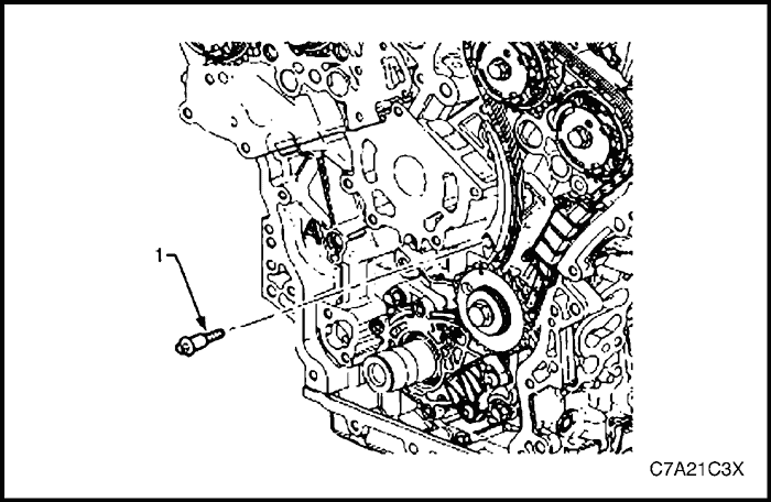
- Align the oil pump gerotor with the crankshaft flats and fit the oil pump assembly to the engine block.
- Align the pump body (2) with the mounting holes in the cylinder block.
- Install the oil pump bolt (1).
Tighten
Tighten the oil pump attaching bolt to 23 N•m (17 lb-ft).
- Install the primary timing chain. Refer to "Timing Chain Components"
in this section.
Camshaft Position Actuator Assembly
Caution : Setting the camshaft timing is required whenever the camshaft drive system is disturbed to ensure the relationship between any chain and sprocket is not lost. Even when only one sprocket is involved, multiple crankshaft rotations will not produce conditions where correct timing can be confirmed. If required, follow the bank 2 Secondary Camshaft Chain Components reinstallation procedure to reset the camshaft timing.
Removal Procedure
- Remove the engine assembly.
Bank 1
- Remove the bank 1 cylinder head cover. Refer to "Cylinder Head Cover"
in this section.
- Remove the camshaft position sensor. Refer to Section 1F3, Engine Controls - HFV6 3.2L.
- Remove the camshaft position actuator solenoids. Refer to Section 1F3, Engine Controls - HFV6 3.2L.
- Remove the crankshaft pulley. Refer to "Crankshaft Pulley"
in this section.
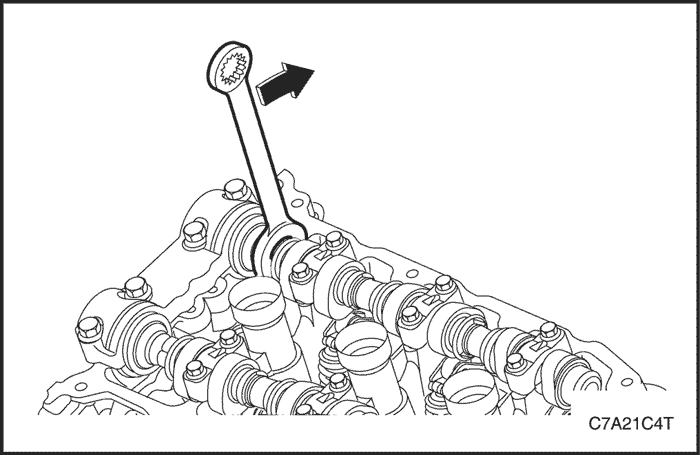
- Install the crankshaft rotation socket Tool No. EN-46111 onto the crankshaft.
- Rotate the crankshaft until the camshafts are in a neutral low tension position. The camshaft flats (1) will be parallel with the cylinder head cover rail (2).
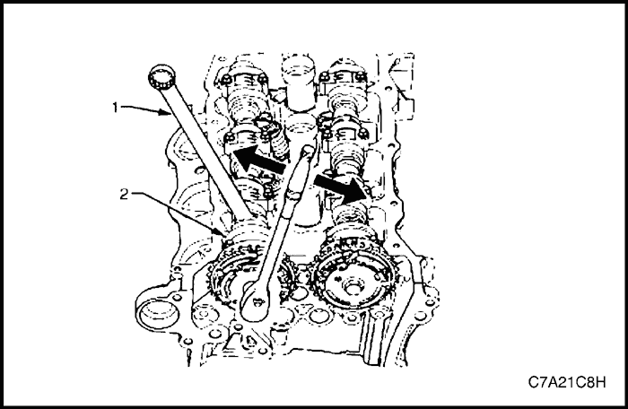
- Install Tool No. EN-46105 - 1 (1) onto the bank of the bank 1 cylinder head (3) camshafts (2).
Note :
-
- Use an open-end spanner (1) at the camshaft hex (2) to prevent camshaft/engine rotation.Disassemble the pump only to diagnose oil related concern. A disassembled oil pump must not be reused: it must be replaced.
- Do not remove the camshaft position actuator bolt at this time.
- Loosen the camshaft position actuator bolt.
Note : If you have already removed the camshaft timing chain, proceed to Step 12.
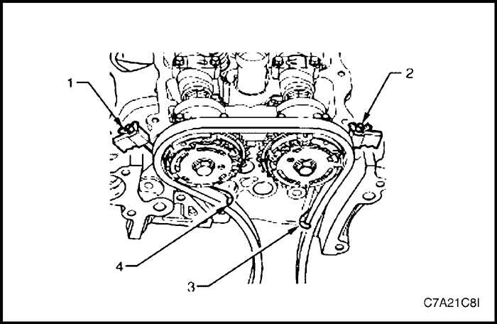
Caution : Ensure the tips of Tool No. EN-46108 are fully engaged into the timing chain and the wing nuts are tight and the timing chain is taught.
- Install Tool No. EN-46108 (1 and 2) to retain the timing chain (3 and 4).
- Firmly tighten the wing nuts of Tool No. EN-46108.
Note : Ensure the camshaft timing chain and the camshaft position actuators are marked for correct reassembly.
- Mark the timing chain and the respective location on both camshaft position actuators.
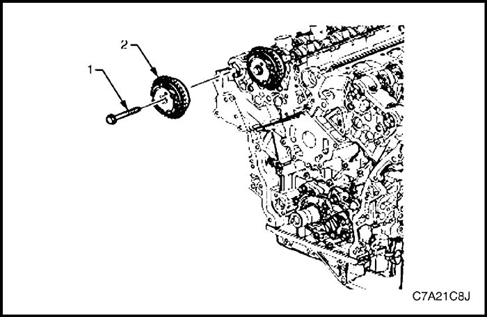
- Remove the bolt (1) attaching the bank 1 exhaust camshaft position actuator (2) and remove the actuator.
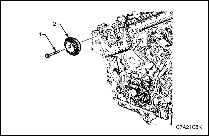
- Remove the bolt (1) attaching bank 1 intake camshaft position actuator (2) and remove the actuator.
Bank 2
- Remove the bank 2 cylinder head cover. Refer to "Cylinder Head Cover"
in this section.
- Remove the camshaft position sensor. Refer to Section 1F3, Engine Controls - HFV6 3.2L.
- Remove the camshaft position actuator solenoids. Refer to Section 1F3, Engine Controls - HFV6 3.2L.
- Remove the crankshaft pulley. Refer to "Crankshaft Pulley"
in this section.
- Install the crankshaft rotation socket Tool No. EN-46111 onto the crankshaft.
- Rotate the crankshaft until the camshafts are in a neutral low tension position. The camshaft flats (1) will be parallel with the cylinder head cover rail (2).
- Install Tool No. EN-46105 - 1 (1) onto the bank of the bank 2 cylinder head camshafts (2).
Note :
-
- Use an open-end spanner (1) at the camshaft hex (2) to prevent camshaft/engine rotation.
- Do not remove the camshaft position actuator bolt at this time.
- Loosen the camshaft position actuator bolt.
Note : If you have already removed the camshaft timing chain, proceed to Step 12.
Caution : Ensure the tips of Tool No. EN-46108 are fully engaged into the timing chain and the wing nuts are tight and the timing chain is taught.
- Install Tool No. EN-46108 (1 and 2) to retain the timing chain (3 and 4).
- Firmly tighten the wing nuts of Tool No. EN-46108.
Note : Ensure the camshaft timing chain and the camshaft position actuators are marked for correct reassembly.
- Mark the timing chain and the respective location on both camshaft position actuators.
- Remove the bolt (1) attaching the bank 1 exhaust camshaft position actuator (2) and remove the actuator.
- Remove the bolt (1) attaching bank 1 intake camshaft position actuator (2) and remove the actuator.
Clean
- Clean the exterior of each camshaft position actuator with solvent.
- Dry the timing components with compressed air.
Inspection
- Inspect the front of each camshaft position actuator for the following:
- Sprocket damage (1),
- Reluctor/sensor wheel damage (2), and
- Camshaft position actuator bolt seating/sealing inner hub flange damage (3).
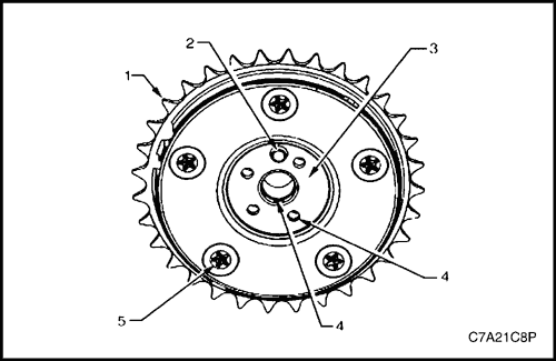
- Inspect the back of each camshaft position actuator for the following:
- Sprocket damage (1),
- Camshaft locating pin damage (2),
- Camshaft seating/sealing inner hub flange damage (3),
- Blockage to the oil passages (4), and
- Loose or missing housing bolts (5).
Installation Procedure
- Installation should follow the removal procedure in the reverse order.
- Align the actuators and timing chain with the marks made during removal.
- Install the camshaft position actuators.
Tighten
Tighten the camshaft position actuator attaching bolts to 58 N•m (43 lb-ft).
- Remove the timing chain retention tools.
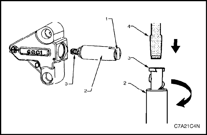
Camshaft
Removal Procedure
Bank 1
- Remove the bank 1 cylinder head cover. Refer to "Cylinder Head Cover"
in this section.
- Remove the bank 1 cylinder head camshaft position actuators. Refer to "Camshaft Position Actuator Assembly"
in this section.
- Remove the Tool No. EN-46105 - 1 (1) from the bank 1 cylinder head camshafts (2).
Note : Tool No. EN-46105 was installed as part of the bank 1 cylinder head camshaft position actuator removal procedure.
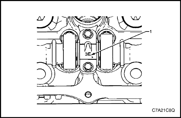
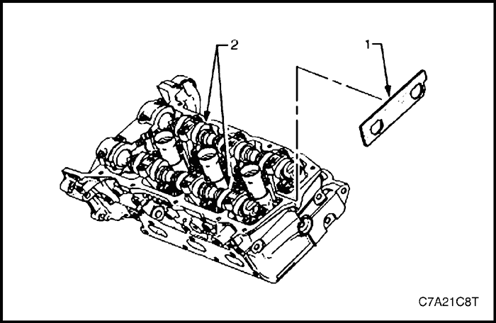
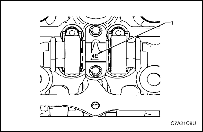
- Observe the markings (1) on the bearing caps. Each bearing cap is marked to identify its location. The markings have the following meanings:
- The raised feature must always be oriented toward the center of the cylinder head.
- An I indicates the intake camshaft.
- An E indicates the exhaust camshaft.
- The number indicates the journal position from the front of the engine.
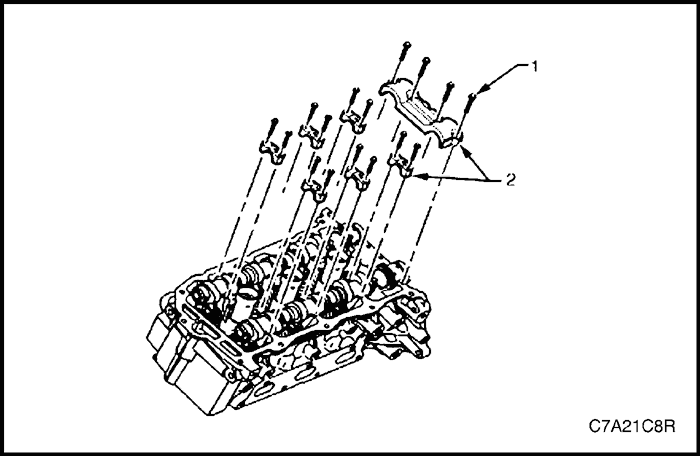
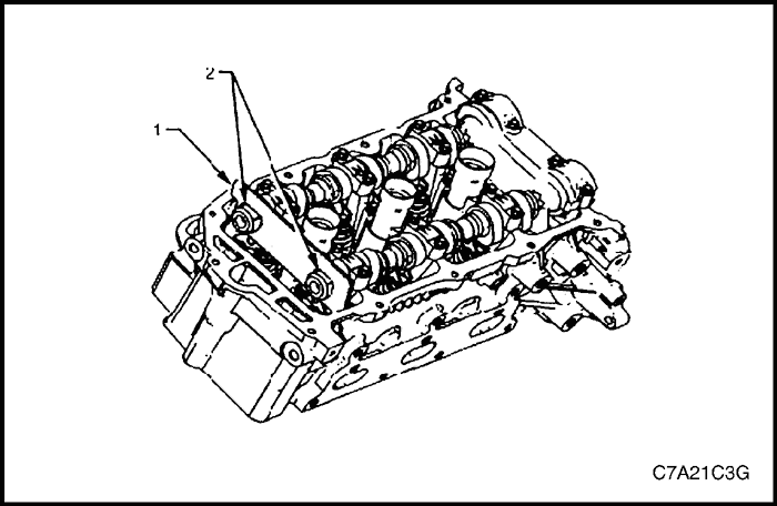
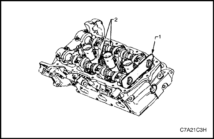
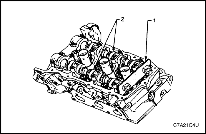
- Remove the camshaft bearing cap bolts (1) and caps (2).
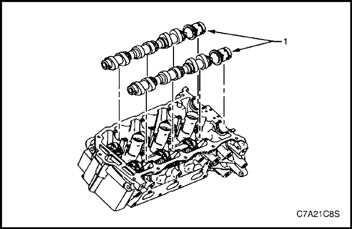
- Remove the camshafts (1).
- Clean the camshaft in solvent and dry it with compressed air.
Bank 2
- Remove the bank 2 cylinder head camshaft position actuators. Refer to "Camshaft Position Actuator Assembly"
in this section.
- Remove Tool No. EN-46105 - 1 (1) from the bank 2 camshafts.
Note : Tool No. EN-46105 was installed as part of the bank 2 cylinder head camshaft position actuator removal procedure.
- Observe the markings (1) on the bearing caps. Each bearing cap is marked in order to identify its location. The markings have the following meanings:
- The raised feature must always be oriented toward the center of the cylinder head.
- An I indicates the intake camshaft.
- An E indicates the exhaust camshaft
- The number indicates the journal position from the front of the engine.
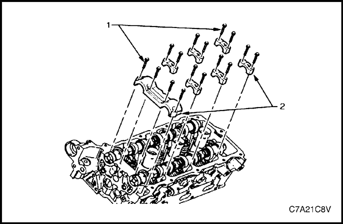
- Remove the camshaft bearing cap bolts (1) and caps (2).
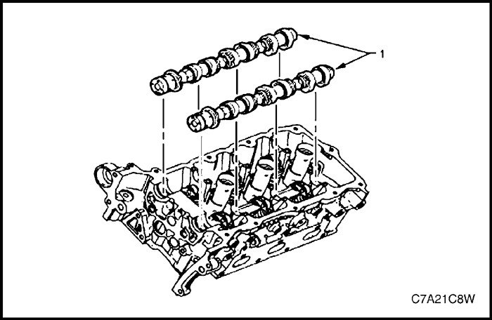
- Remove the camshafts (1).
- Clean the camshaft in solvent and dry it with compressed air.
Inspection
Camshaft Visual Inspection
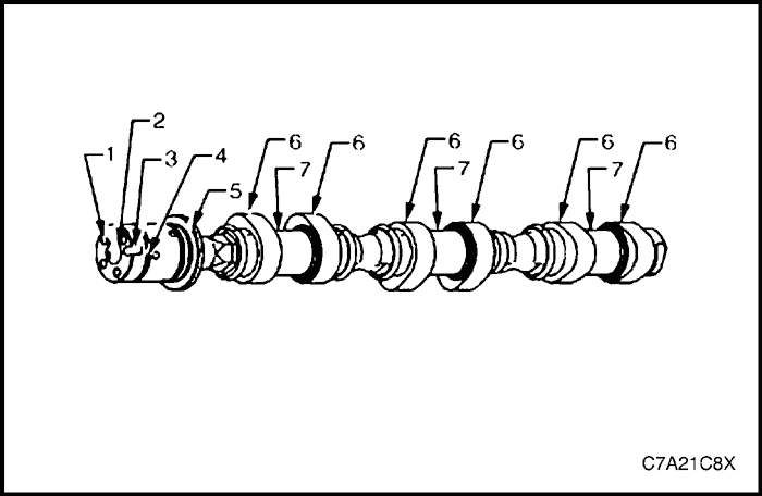
- Inspect the camshaft oil feed holes (1) to the camshaft position actuator for dirt, debris or blockage.
- Inspect the threaded hole (2) for damage.
- Inspect the camshaft position actuator locating notch (3) for damage or wear.
- Inspect the camshaft sealing grooves (4) for damage.
- Inspect the camshaft thrust surface (5) for damage.debris or blockage.
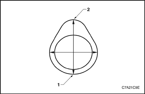
- Inspect the camshaft lobes (6) and journals (7) for the following conditions:
- Excessive scoring or pitting
- Discoloration from overheating
- Deformation from excessive wear, especially the camshaft lobes
- If any of the above conditions exist on the camshaft, replace the camshaft.
Camshaft Measurement
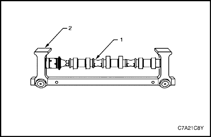
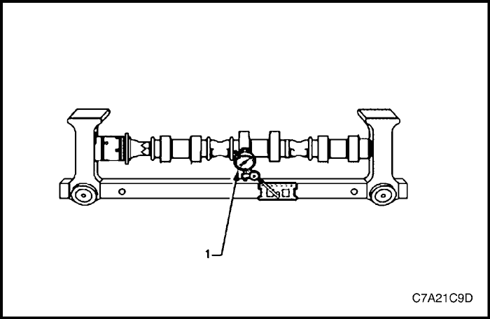
- With the camshaft (1) in a suitable fixture (2), measure the camshaft for wear.
Caution : No machining of the camshaft is allowed.
Note : If the camshaft measures outside the specified range, replace the camshaft.
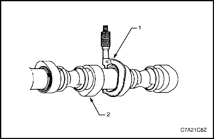
- Measure the camshaft (2) journals for diameter and out-of-round using an outside micrometer (1).
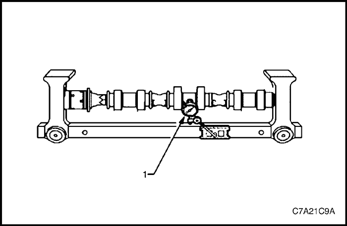
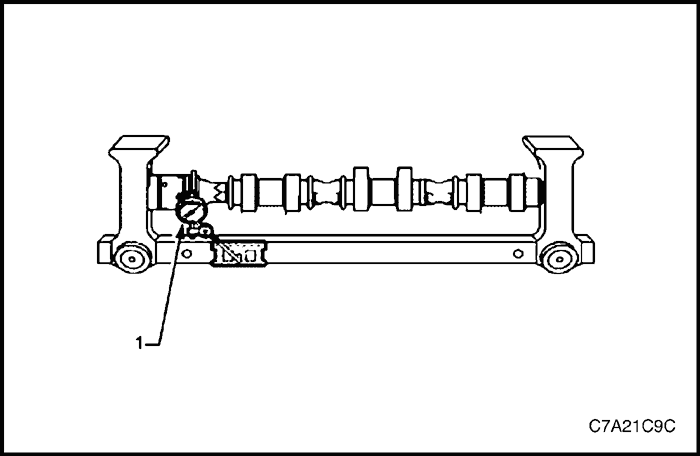
- Measure the camshaft runout using a dial indicator (1).
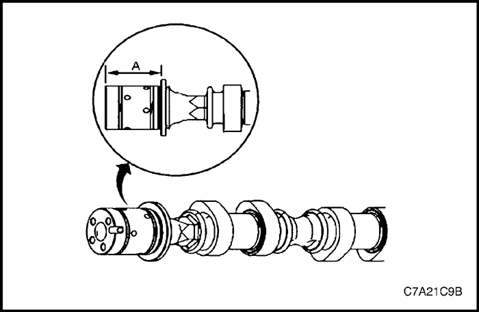
- Measure the camshaft thrust width for wear using a depth micrometer (A).
- Measure the camshaft thrust wall surface for runout using a dial indicator (1).
- Measure the camshaft lobes for wear using a dial indicator (1).
- Place the dial indicator tip on the base circle (1) of the camshaft lobe.
- Set the dial indicator at zero.
- Rotate the camshaft until the indicator tip is at the highest point (2) on the lobe. This reading is the lift of the camshaft lobe.
Installation Procedure
Bank 1
- Ensure the camshaft sealing rings (1) are in place in the camshaft grooves.
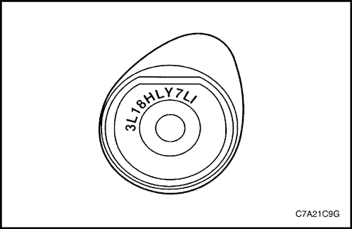
- Select the correct camshaft for the particular installation location. ID markings are on the rear end of each camshaft. The ID markings are defined as follows:
-
- a. The first five digits refer to the date and time of production.
-
- b. Digits six through nine refer to engine production code.
- LY7 = Alloytec190 engine.
-
- c. The last two digits refer to position:
- LI = bank 2 intake.
- LE = bank 2 exhaust.
- RI = bank 1 intake.
- RE = bank 1 exhaust.
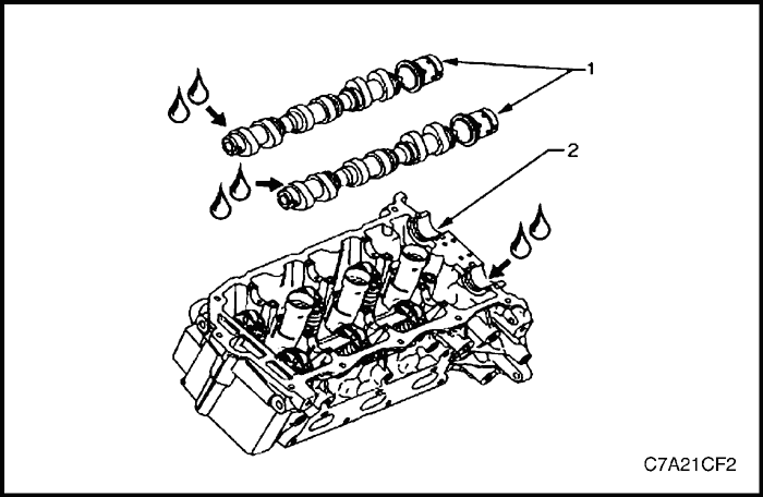
- Apply a liberal amount of engine oil to the camshaft (1) journals and the bank 1 cylinder head camshaft carriers (2).
- Apply a liberal amount of engine oil to the camshaft (1) journals and the bank 1 cylinder head camshaft carriers (2).
Note : Install the camshaft position actuator bolts but do not tighten at this stage.
- Ensure the camshaft lobes are in the neutral position with the flats on the back of the camshafts up and parallel (1) with the bank 1 cylinder head cylinder head cover rail (2).
- Ensure the marks on the bank 1 exhaust camshaft position actuator and timing chain, made prior to the disassemble operation are aligned.
- Ensure the marks on the bank 1 intake camshaft position actuator and timing chain, made prior to the disassemble operation are aligned.
- Observe the markings on the bank 1 cylinder head camshaft bearing caps. Each bearing cap is marked (1) to identify its location. The markings have the following meanings:
- The raised feature must always be oriented toward the center of the cylinder head.
- The I indicates the intake camshaft.
- The E indicates the exhaust camshaft.
- The number 1, 3, 5 indicates the cylinder position from the front of the engine.
- Apply a liberal amount of engine oil to the camshaft bearing caps.
- Apply a liberal amount of engine oil to the camshaft bearing caps.
- Install the remaining bearing caps (2) with their orientation mark toward the center of the cylinder head.
- Hand starts all the camshaft bearing cap bolts (3).
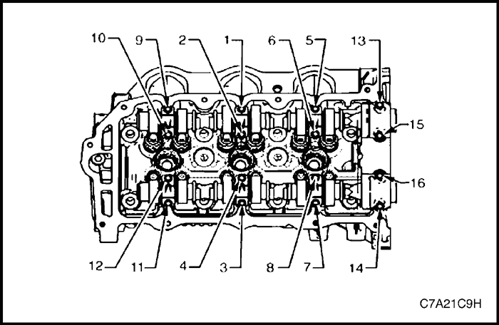
- Install the camshaft bearing cap bolts.
Tighten
Tighten the camshaft bearing cap attaching bolt to 10 N•m (89 lb-in).
- Loosen the center intake camshaft bearing cap bolts 1 and 2, and the center exhaust camshaft bearing cap bolts 3 and 4.
- Retighten the center camshaft bearing cap bolts 1, 2, 3 and 4.
Tighten
Tighten the camshaft bearing cap attaching bolt to 10 N•m (89 lb-in).
- Install the bank 1 cylinder head camshaft position actuators. Refer to "Camshaft Position Actuator Assembly"
in this section.
Bank 2
- Ensure the camshaft sealing rings (1) are in place in the camshaft grooves.
- Select the correct camshaft for the particular installation location. ID markings can be found on the rear end of each camshaft. The ID markings are defined as follows:
-
- a. The first five digits refer to the date and time of production.
-
- b. Digits six through nine refer to engine production code.
- LY7 = Alloytec 190 engine.
-
- c. The last two digits refer to position:
- LI = bank 2 intake.
- LE = bank 2 exhaust.
- RI = bank 1 intake.
- RE = bank 1 exhaust.
- Apply a liberal amount of engine oil to the camshaft journals and the bank 2 cylinder head camshaft carriers.
- Position the camshafts (1) on the cylinder head and assemble the camshaft actuators to the camshafts.
Note : Install the camshaft position actuator bolts but do not tighten at this stage.
- Ensure the camshaft lobes are in the neutral position with the flats on the back of the camshafts up and parallel (1) with the bank 2 cylinder head cylinder head cover rail.
- Ensure the marks on the bank 2 exhaust camshaft position actuator and timing chain, made prior to the disassemble operation are aligned.
- Ensure the marks on the bank 2 intake camshaft position actuator and timing chain, made prior to the disassemble operation are aligned.
- Observe the markings on the bank 2 cylinder head camshaft bearing caps. Each bearing cap is marked (1) to identify its location. The markings have the following meanings:
- The raised feature must always be oriented toward the center of the cylinder head.
- The I indicates the intake camshaft.
- The E indicates the exhaust camshaft.
- The number 2, 4, 6 indicates the cylinder position from the front of the engine.
- Apply a liberal amount of engine oil to the camshaft bearing caps.
- Install the camshaft bearing thrust cap (1) in the first journal of the bank 2 cylinder head.
- Install the remaining bearing caps (2) with their orientation mark toward the center of the cylinder head.
- Hand starts all the camshaft bearing cap bolts (3).
- Install the camshaft bearing cap bolts.
Tighten
Tighten the camshaft bearing cap bolt to 10 N•m (89 lb-in).
- Loosen the center intake camshaft bearing cap bolts 1, and 2, and the center exhaust camshaft bearing cap bolts 3 and 4.
- Retighten the center camshaft bearing cap bolts 1, 2, 3 and 4.
Tighten
Tighten the camshaft bearing cap bolt to 10 N•m (89 lb-in).
- Install the bank 2 cylinder head camshaft position actuators. Refer to "Camshaft Position Actuator Assembly"
in this section.
 |
|
 |
|
| © Copyright Chevrolet Europe. All rights reserved |