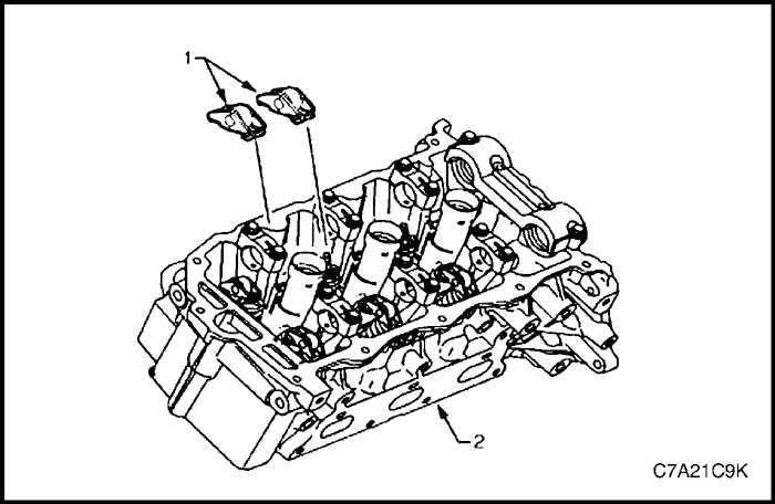


Rocker Arm
Removal Procedure
- Remove the camshafts from the appropriate cylinder head. Refer to "Camshaft" in this section.
Caution : If the rocker arms are being reused, they must be reinstalled in their original location.
Note : Record the rocker arm positions during removal.
- Remove the rocker arm (1) from the cylinder head (2).


Clean and Inspection
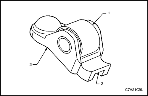
- Inspect the rocker arm roller (1) for the following:
- flat spots,
- excessive scoring and pitting, and
- ensure the roller spins freely
- Inspect the rocker arm valve tip area (2).
- Inspect the rocker arm stationary hydraulic lash adjuster (SHLA) pivot area (3).
- Replace the rocker arm as required.


Installation Procedure
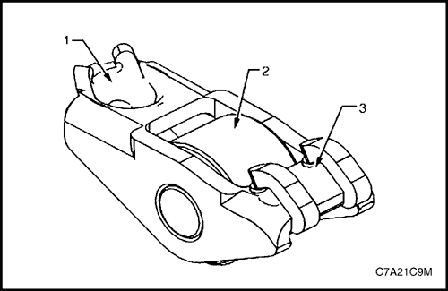
- Apply a liberal amount of commercially available camshaft / lifter prelube or equivalent to the pivot pocket (1), roller (2) and valve slot (3) areas of the camshaft followers.
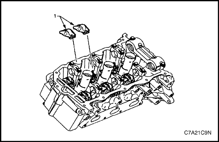


Caution :
- The rocker arm (1) must be positioned squarely on the valve tip so the full width of the roller will completely contact the camshaft lobe.
- If the rocker arms are being reused, they must be reinstalled in their original location.
- Place the rocker arm in position on the valve tip and stationary hydraulic lash adjuster (SHLA). The rounded head end of the arm seats on the SHLA while the flat end seats on the valve tip.
- Clean the camshaft journals and carriers with a clean, lint-free cloth.
- Reinstall the camshafts. Refer to "Camshaft" in this section.


Stationary Hydraulic Lash Adjuster
Removal Procedure
- Remove the rocker arms from the appropriate cylinder head. Refer to "Rocker Arm" in this section.
Caution :
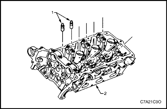
- Do not stroke/cycle the stationary hydraulic lash adjuster (1) plunger without oil in the lower pressure chamber.
- Do not allow the stationary hydraulic lash adjuster to tip over, plunger down, after the oil fill.
- Remove the stationary hydraulic lash adjuster (SHLA) from the cylinder head (2).


Clean and Inspection
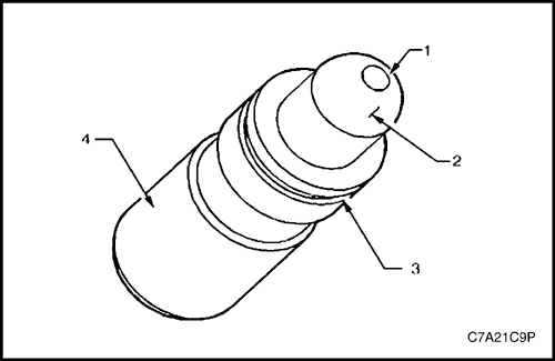
- Inspect the stationary hydraulic lash adjuster (SHLA) in the following areas:
- a plugged oil passage (1),
- a scored or worn camshaft follower pivot area (2),
- a damaged or broken retainer (3), and
- a severely scuffed or worn SHLA body (4).
- Replace the SHLA as required.


Installation Procedure
Caution : Ensure each lash adjuster (1) is filled with clean engine oil and the adjuster does not tip over, plunger down, before the installation. The loss of oil in the adjuster lower pressure chamber, or the dry stroking/cycling of the adjuster plunger, will allow air to enter the high pressure chamber of the valve lifter. Air in the high pressure chamber of the adjuster may not be purged causing cavitation and extensive engine component damage.
- Fill the stationary hydraulic lash adjuster (SHLA) with clean engine oil. Take precautions to prevent scratching the pivot sphere area of the SHLA.
- Lubricate the SHLA bores in the cylinder head with clean engine oil.
- Install the SHLA in the cylinder head (2).
- Apply a liberal amount of commercially available camshaft/lifter prelube to the SHLA pivot spheres.
- Install the rocker arms. Refer to "Rocker Arm" in this section.


Cylinder Head Assembly
Removal Procedure
Bank 1
- Remove the engine assembly. Refer to "Engine Assembly" in this section.
- Remove the intake manifold assembly. Refer to "Intake Manifold Assembly" in this section.
- Remove the exhaust manifold. Refer to "Exhaust Manifold Assembly" in this section.
- Remove engine harness ground terminal attaching bolts from the cylinder head.
- Remove the bank 1 side secondary timing chain. Refer to "Timing Chain Components" in this section.
- Remove the camshaft position actuators. Refer to "Camshaft Position Actuator Assembly" in this section.
- Remove the power steering fluid supply line retaining bolt from the cylinder head.
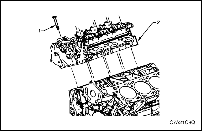
- Remove the cylinder head attaching bolt (1), eight places.
Note : There is no bolt fitted to the hole in the bank of the bank 1 cylinder head.
- Remove the cylinder head.
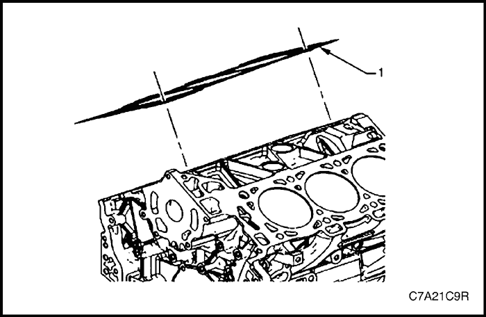


- Remove and discard the cylinder head gasket (1).


Bank 2
- Remove the engine assembly. Refer to "Engine Assembly" in this section.
- Remove the intake manifold assembly. Refer to "Intake Manifold Assembly" in this section.
- Remove the exhaust manifold. Refer to "Exhaust Manifold Assembly" in this section.
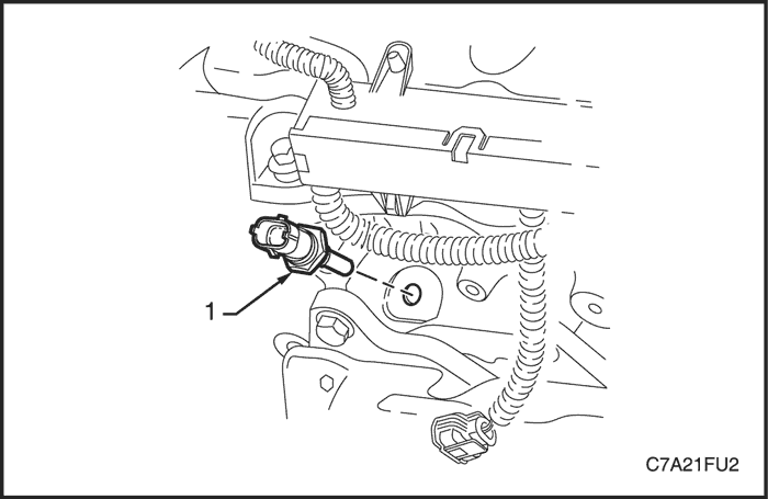
- Remove the engine coolant temperature (ECT) sensor. Refer to Section 1F3, Engine Controls - HFV6 3.2L.


- Remove engine harness ground terminal attaching bolt from cylinder head.
- Remove the bank 2 secondary timing chain. Refer to "Timing Chain Components" in this section.
- Remove the camshaft position actuators. Refer to "Camshaft Position Actuator Assembly" in this section.
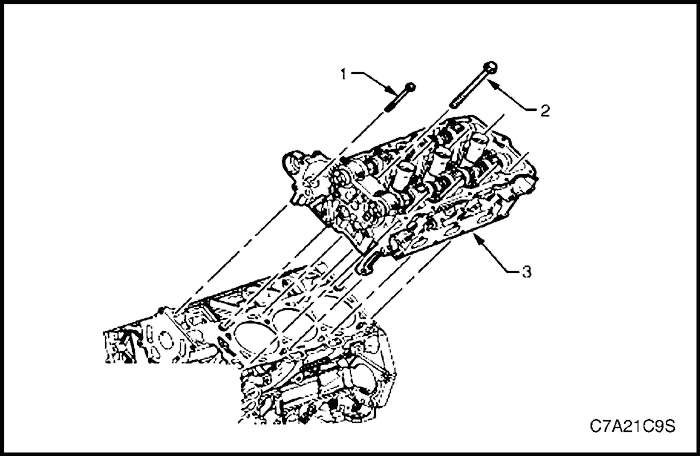
- Remove the front cylinder head attaching bolt (1), two places.
- Remove the cylinder head attaching bolt (2), eight places.
- Remove the cylinder head (3).
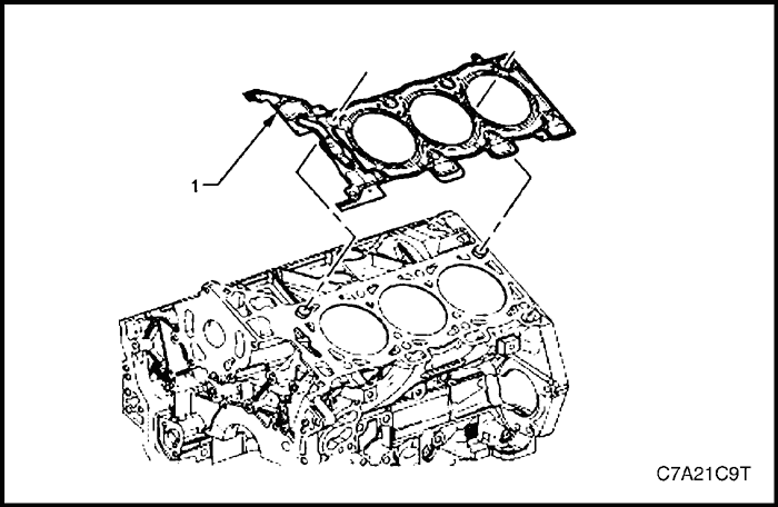


- Remove and discard the cylinder head gasket (1).


Installation Procedure
Bank 1
- Installation should follow the removal procedure in the reverse order.
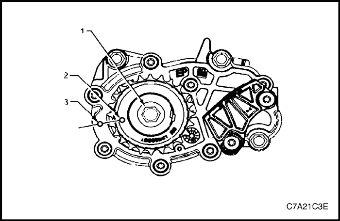
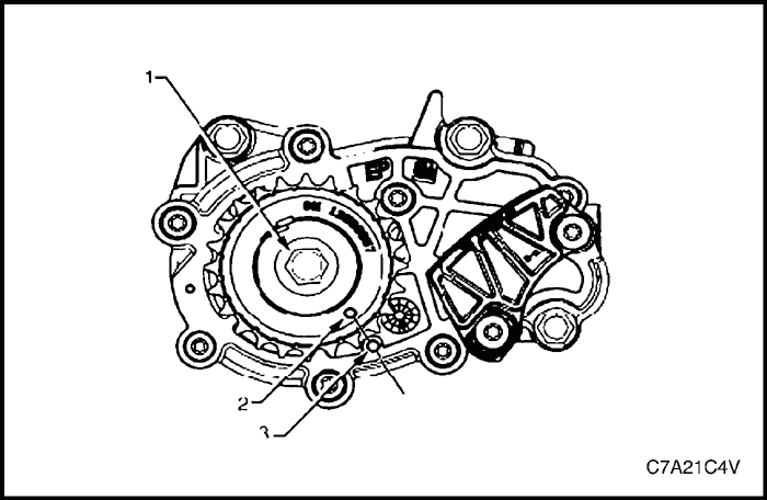
- Using crankshaft rotation Tool No. EN-46111 (1), align the crankshaft sprocket timing mark (2) with the indexing mark (3) on the oil pump housing.


- Ensure the deck face is clean and the cylinder head locating pins are securely mounted in the cylinder block deck face.
- Install a new cylinder head gasket (1) using the deck face locating pins for retention.


- Align the cylinder head with the locating pins.
- Place the cylinder head in position on the deck face.
Note : Do not allow oil on the cylinder head bolt bosses.
Caution : Do not reuse the old cylinder head bolts (1 to 8 inclusive).
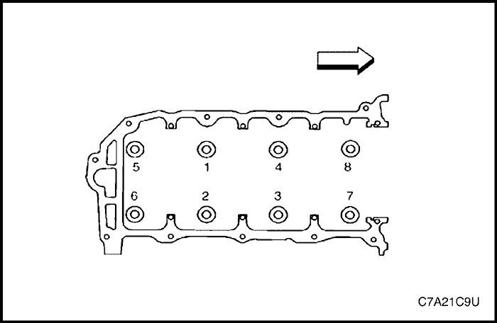


- Install new cylinder head bolt (1) eight places and tighten in the sequence shown.
Tighten
Tighten the cylinder head bolt to 45 N•m (33 lb-ft) and turns the bolt another 120° using the angular torque gauge KM-470-B.
- Install any other parts that were previously removed.


Bank 2
- Installation should follow the removal procedure in the reverse order.
- Using crankshaft rotation Tool No. EN-46111 (1), align the crankshaft sprocket timing mark (2) with the indexing mark (3) on the oil pump housing.


- Ensure the deck face is clean and the cylinder head locating pins are securely mounted in the cylinder block deck face.
- Install a new cylinder head gasket (1) using the deck face locating pins for retention.


- Align the cylinder head with the locating pins.
- Place the cylinder head in position on the deck face.
Note : Do not allow oil on the cylinder head bolt bosses.
Caution : Do not reuse the old cylinder head bolts (1 to 8 inclusive).
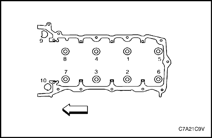


- Install new cylinder head bolt (1) eight places and tighten in the sequence shown.
Tighten
Tighten the cylinder head bolt to 45 N•m (33 lb-ft) and turns the bolt another 120° using the angular torque gauge KM-470-B.
- Install the front cylinder head bolt (2), two places, and tighten in the sequence shown (9 and 10).
Tighten
Tighten the front cylinder head bolt to 15 N•m (11 lb-ft) and turns the bolt another 60° using the angular torque gauge KM-470-B.
- Install any other parts that were previously removed.


Engine Mount Assembly (RH Side)
Tools Required
DW110-060 Engine Assembly Support Fixture
Removal Procedure
Caution : Only lift the engine far enough to take the weight off the transaxle front mount assembly, or damage to the mount and lifting equipment failure may occur.
- Remove the engine dress cover. Refer to "Engine Dress Cover" in this section.
- Remove the air cleaner assembly. Refer to Section 1C2, Engine Mechanical - HFV6 3.2L.
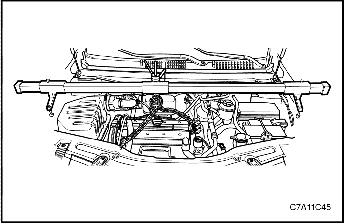
- Support the engine assembly using the engine assembly support fixture DW110-060.
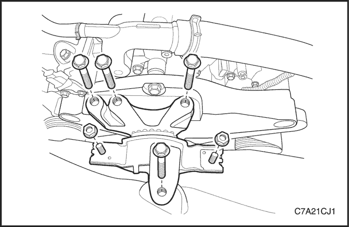


- Remove the engine mount adapter retaining bolts from the engine mount support bracket.
- Remove the engine mount frame side bracket retaining bolt and nuts.
- Remove the engine mount assembly.


Installation Procedure
- Install the engine mount assembly.
Tighten
- Tighten the engine mount frame side bracket retaining bolt to 100 N•m (74 lb-ft) and nuts to 90 N•m (66 lb-ft).
- Tighten the engine mount adapter retaining bolts to 50 N•m (37 lb-ft).
- Remove the engine assembly support fixture DW110-060.
- Install the air cleaner assembly. Refer to Section 1C2, Engine Mechanical - HFV6 3.2L.
- Install the engine dress cover. Refer to "Engine Dress Cover" in this section.


Transaxle Mount Assembly (LH Side)
Tools Required
DW110-060 Engine Assembly Support Fixture
Removal Procedure
- Remove the battery and battery tray. Refer to Section 1F3, Engine Controls - HFV6 3.2L.
- Remove the engine dress cover. Refer to "Engine Dress Cover" in this section.


Caution : Only lift the engine far enough to take the weight off the transaxle front mount assembly, or damage to the mount and lifting equipment failure may occur.
- Support the engine assembly using the engine assembly support fixture DW110-060.
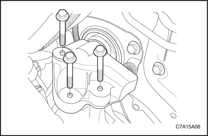


- Remove the transaxle mount bracket retaining bolts from the transaxle.
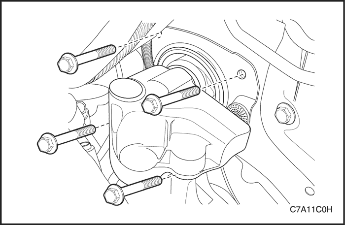


- Remove the transaxle mount assembly retaining bolts from the left front longitudinal.
- Remove the transaxle mount assembly.
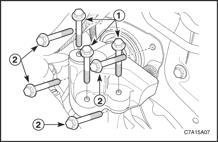


Installation Procedure
- Install the transaxle mount assembly.
Tighten
- Tighten the transaxle mount assembly retaining bolts (2) to 37 N•m (27 lb-ft).
- Tighten the transaxle mount bracket retaining bolts (1) to 50 N•m (37 lb-ft).
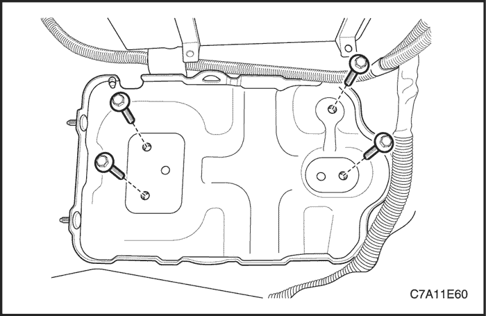


- Remove the engine assembly support fixture DW110-060.
- Install the battery and battery tray. Refer to Section 1F3, Engine Controls - HFV6 3.2L.
- Install the engine dress cover. Refer to "Engine Dress Cover" in this section.


Transaxle Front Mount Assembly
Tools Required
DW110-060 Engine Assembly Support Fixture
Removal Procedure
Caution : Only lift the engine far enough to take the weight off the transaxle front mount assembly, or damage to the mount and lifting equipment failure may occur.
- Remove the engine dress cover. Refer to "Engine Dress Cover" in this section.
- Support the engine assembly using the engine assembly support fixture DW110-060.
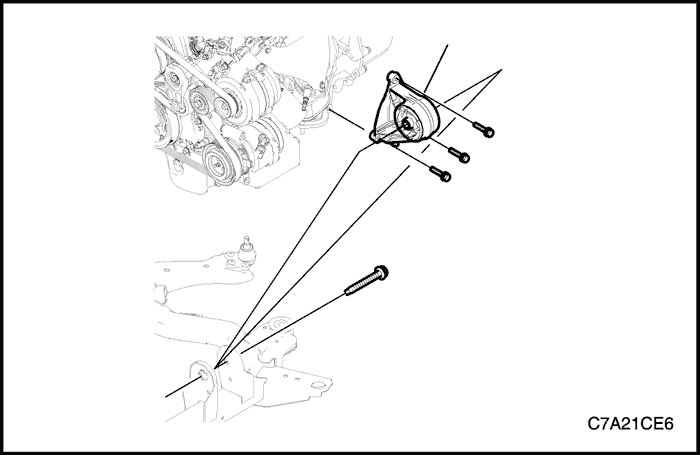


- Remove the transaxle front mount-to-cradle through bolt.
- Remove the transaxle front mount retaining bolts from the transaxle.
- Remove the transaxle front mount assembly.


Installation Procedure
- Install the transaxle front mount assembly.
Tighten
Tighten the transaxle front mount retaining bolts to 50 N•m (37 lb-ft).
Caution : Before tightening the transaxle front mount through bolt swing the engine assembly backwards and forwards or from the side to side for the proper alignment.
- Install the transaxle front mount through bolt.
Tighten
Tighten the transaxle front mount-to-cradle through bolt to 90 N•m (66 lb-ft).
- Remove the engine assembly support fixture DW110-060.
- Install the engine dress cover. Refer to "Engine Dress Cover" in this section.


Transaxle Rear Mount Assembly
Tools Required
DW110-060 Engine Assembly Support Fixture
Removal Procedure
Caution : Only lift the engine far enough to take the weight off the transaxle front mount assembly, or damage to the mount and lifting equipment failure may occur.
- Remove the engine dress cover. Refer to "Engine Dress Cover" in this section.
- Support the engine assembly using the engine assembly support fixture DW110-060.
- Remove the transfer case. Refer to Section 5D, Transfer Case.
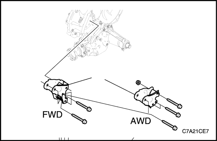


- Remove the transaxle rear mount-to-bracket through bolt.
- Remove the transaxle rear mount bracket retaining bolts and nuts from the transaxle.
- Remove the transaxle rear mount bracket.
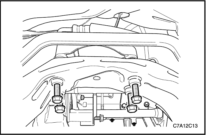


- Remove the transaxle rear mount retaining bolts from the cradle.
- Remove the transaxle rear mount.


Installation Procedure
- Install the transaxle rear mount to the cradle.
Tighten
Tighten the transaxle rear mount retaining bolts to 90 N•m (66 lb-ft).


- Install the transaxle rear mount bracket to the transaxle.
Tighten
Tighten the transaxle rear mount bracket retaining bolts to 90 N•m (66 lb-ft).
Caution : Before tightening the transaxle rear mount through bolt, swing the engine assembly backwards and forwards or from the side to side for the proper alignment.
- Install the transaxle rear mount through bolt.
Tighten
Tighten the transaxle rear mount-to-bracket through bolt to 90 N•m (66 lb-ft).
- Install the transfer case. Refer to Section 5D, Transfer Case.
- Remove the engine assembly support fixture DW110-060.
- Install the engine dress cover. Refer to "Engine Dress Cover" in this section.


Engine Assembly
Tools Required
EN-48243 Engine Assembly Remove/Install Pallet
EN-48244 Engine Assembly Remove/Install Pallet Supporter
Removal Procedure
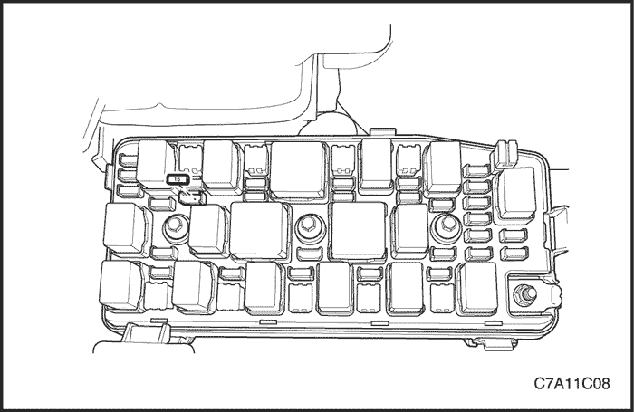
- Remove the fuel pump fuse.
- Start the engine. After it stalls, crank the engine for 10 seconds to rid the fuel system of fuel pressure.
- Drain the engine oil.
- Drain the engine coolant. Refer to Section 1D3, Engine Cooling - HFV6 3.2L.
- Drain the power steering oil.
- Drain the transaxle oil. Refer to Section 5A, AISIN 55-51LE Automatic Transaxle or Section 5B, Five-Speed Manual Transaxle (D33).
- Discharge the air conditioning system, if equipped. Refer to Section 7B, Manual Control Heating, Ventilation, and Air Conditioning System.


- Remove the engine dress cover. Refer to "Engine Dress Cover" in this section.
- Remove the air cleaner assembly. Refer to "Air Cleaner Assembly" in this section.


- Disconnect the upper radiator hose from the water outlet port.
- Disconnect the water hose from the water outlet port.
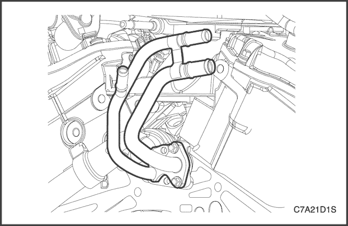


- Disconnect the lower radiator hose from the water pipe.
- Disconnect the heater inlet/outlet hose from the heater inlet/outlet pipe.
- Disconnect the power steering hoses from the power steering fluid reservoir. Refer to Section 6A, Power Steering System.


- Remove the battery. Refer to Section 1E3, Engine Electrical - HFV6 3.2L.
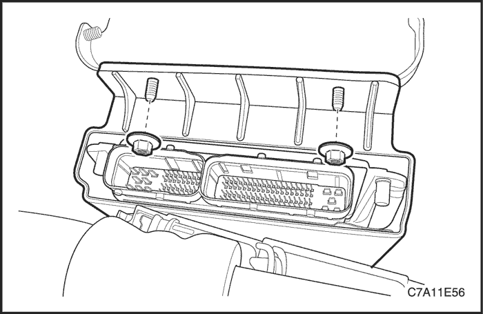
- Remove the ECM. Refer to Section 1F3, Engine Controls - HFV6 3.2L.
- Disconnect the engine fuse block main cable.
- Disconnect the ground terminal wiring harness.
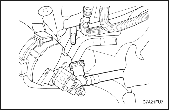


- Disconnect the fuel feed line.
- Disconnect the evaporative (EVAP) emission canister purge front hose from the EVAP emission canister purge solenoid valve.
- Disconnect the brake booster vacuum hose from the rear cylinder head cover.
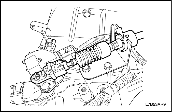


- Disconnect the transmission range (TR) switch electrical connector. Refer to Section 5A, AISIN 55-51 LE Automatic Transaxle or Section 5B, Five-Speed Manual Transaxle (D33).
- Disconnect the shift control cable from the transmission.
- Disconnect the transmission oil cooling pipe from the radiator. Refer to Section 5A, AISIN 55-51 LE Automatic Transaxle
- Disconnect the transmission oil cooling pipe from the radiator. Refer to Section 5B, Five-Speed Manual Transaxle (D33).


- Disconnect the stabilizer link. Refer to Section 2D, Rear Suspension.
- Disconnect the tie rod end joint. Refer to Section 2D, Rear Suspension.
- Disconnect the control arm joint. Refer to Section 2D, Rear Suspension.
- Remove the left and right axle shaft. Refer to Section 3A, Front Drive Axle or Section 3B, Rear Drive Axle.
- Disconnect the interm shaft from the power steering gear. Refer to Section 6C, Power Steering Gear.
- Remove the propeller shaft. Refer to Section 3B, Rear Drive Belt.
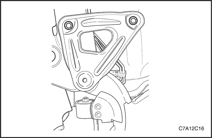


- Remove the cradle support bracket retaining bolts from the rear of the cradle.
- Remove the cradle mounting bolts from the front of the cradle.


Caution : Make sure that all components have to be set on the exact position on the engine assembly remove/install pallet EN-48243 or pallet supporter EN-48244 as shown.
- 1 ~ 4 : Cradle Supporter
- A :Diesel Engine Oil Pan Supporter
- B : FAM II 2.4D Engine Oil Pan Supporter
- C & D : HFV6 3.2L Engine Oil Pan Supporter
- E :Manual Transaxle Supporter
- F : Automatic Transaxle Supporter
- G : Transfer Case Supporter (M/T & A/T)
- H : Transaxle Mount Supporter (M/T & A/T)
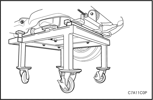


Caution : Only lower the vehicle far enough to take the weight off the engine and transaxle mount, or damage to the mount and pallet/pallet supporter failure may occur.
- Lower the vehicle and position the engine assembly on to the engine assembly remove/install pallet EN-48243 with the pallet supporter EN-48244 to the cradle.


- Remove the engine mount assembly. Refer to "Engine Mount Assembly" in this section.


- Remove the transaxle mount assembly. Refer to "Transaxle Mount Assembly" in this section.


Caution : Make sure that all the cables, connectors and hoses are disconnected from the engine and transaxle assembly.
- Raise the vehicle to remove from the engine and transaxle assembly clear.
- Remove the engine and transaxle assembly from the vehicle.
- Install the hoist to the engine support bracket and lift the engine assembly far enough to take the weight off the transaxle front and rear mount assembly.
- Remove the transaxle front mount assembly from the cradle. Refer to "Transaxle Front Mount Assembly" in this section.


- Remove the transaxle rear mount assembly from the cradle. Refer to "Transaxle Rear Mount Assembly" in this section.
- Lift the engine assembly and remove the cradle from the engine and transaxle assembly.
- Separate the engine block from the transaxle as follows.
- a. Remove the starter.
- b. Remove the torque converter bolts.
- c. Remove the transaxle to engine block mounting bolts.
- d. Remove the oil flange to transaxle mounting bolts.


Installation Procedure
- Install the torque converter bolts, if necessary.
Tighten
Tighten the torque converter bolts to 65 N•m (48 lb-ft).
- Install the transaxle to the engine block, if necessary.
Tighten
- Tighten the oil pan flange-to-transaxle mounting bolts to 50 N•m (37 lb-ft).
- Tighten the transaxle to engine block mounting bolts (transaxle upper side - 3 Ea, starter side - 1 Ea, transaxle rear mount side - 1 Ea) to 50 N•m (37 lb-ft).


Caution : Make sure that all components have to be set on the exact position on the engine assembly remove/install pallet EN-48243 with the pallet supporter EN-48244.
- Install the engine and transaxle assembly onto the cradle.
Caution : Before tightening the transaxle front mount through bolt, swing the engine assembly backwards and forwards or from the side to side for the proper alignment.
- Install the transaxle front mount assembly.
Tighten
- Tighten the transaxle front mount retaining bolts to 50 N•m (37 lb-ft).
- Tighten the transaxle front mount-to-cradle through bolt to 90 N•m (66 lb-ft).


Caution : Before tightening the transaxle rear mount through bolt, swing the engine assembly backwards and forwards or from the side to side for the proper alignment.
- Install the transaxle rear mount assembly to the cylinder block.
Tighten
- Tighten the transaxle rear mount retaining bolts to 90 N•m (66 lb-ft).
- Tighten the transaxle rear mount-to-bracket through bolt to 90 N•m (66 lb-ft).


- Lift the vehicle.
- Lower the vehicle and position the engine and transaxle assembly with the cradle attached on to the engine assembly remove/install pallet EN-48243 with the pallet supporter EN-48244 to the vehicle.


- Install the transaxle mount. Refer to "Transaxle Mount Assembly" in this section.
Tighten
- Tighten the transaxle mount assembly retaining bolts to 37 N•m (27 lb-ft).
- Tighten the transaxle mount bracket retaining bolts to 50 N•m (37 lb-ft).


- Install the engine mount assembly. Refer to "Engine Mount Assembly" in this section.
Tighten
- Tighten the engine mount frame side bracket retaining bolt to 100 N•m (74 lb-ft) and nuts to 90 N•m (66 lb-ft).
- Tighten the engine mount adapter retaining bolts to 50 N•m (37 lb-ft).


- Install the cradle mounting bolts to the front of the cradle.
Tighten
Tighten the cradle mounting bolts to 155 N•m (114 lb-ft).
- Install the cradle support bracket mounting bolts to 50 N•m (37 lb-ft).


- Connect the stabilizer link. Refer to Section 2D, Rear Suspension.
- Connect the tie rod end joint. Refer to Section 2D, Rear Suspension.
- Connect the control arm joint. Refer to Section 2D, Rear Suspension.
- Install the left and right axle shaft. Refer to Section 3A, Front Drive Axle or Section 3B, Rear Drive Axle.
- Connect the interm shaft to the power steering gear. Refer to Section 6C, Power Steering Gear.
- Install the propeller shaft. Refer to Section 3B, Rear Drive Belt.


- Connect the transmission range (TR) switch electrical connector. Refer to Section 5A, AISIN 55-51 LE Automatic Transaxle or Section 5B, Five-Speed Manual Transaxle (D33).
- Connect the shift control cable to the transmission.
- Connect the transmission oil cooling pipe to the radiator. Refer to Section 5A, AISIN 55-51 LE Automatic Transaxle
- Connect the power steering fluid return cooling pipe. Refer to Section 6A, Power Steering System.


- Connect the fuel feed line.
- Connect the evaporative (EVAP) emission canister purge front hose to the EVAP emission canister purge solenoid valve.
- Connect the brake booster vacuum hose to the rear cylinder head cover.


- Install the battery. Refer to Section 1E3, Engine Electrical - HFV6 3.2L.
- Install the ECM. Refer to Section 1F3, Engine Controls - HFV6 3.2L.
- Connect the engine fuse block main cable.
- Connect the ground terminal wiring harness.


- Connect the lower radiator hose to the water pipe.
- Connect the heater inlet/outlet hose to the heater inlet/outlet pipe.
- Connect the power steering hoses to the power steering fluid reservoir. Refer to Section 6A, Power Steering System.


- Disconnect the upper radiator hose from the water outlet port.
- Disconnect the water hose from the water outlet port.


- Remove the engine dress cover. Refer to "Engine Dress Cover" in this section.
- Remove the air cleaner assembly. Refer to "Air Cleaner Assembly" in this section.


- Install the fuel pump fuse.
- Refill the engine crankcase with engine oil.
- Refill the engine coolant system. Refer to Section 1D3, Engine Cooling - HFV6 3.2L.
- Refill the power steering system and bleed the system. Refer to Section 6A, Power Steering System.
- Refill the A/C refrigerant system, if equipped. Refer to Section 7B, Manual Control Heating, Ventilation and Air Conditioning System.
- Check for any leaks, unusual sounds or all fluid level.


Oil Pan Assembly
Removal Procedure
- Disconnect the negative battery cable.
- Remove the engine assembly. Refer to in this section.
- Remove the front timing cover. Refer to in this section.
- Remove the exhaust front pipe. Refer to Section 1G3, Engine Exhaust.
- Disconnect the oil level sensor connector.
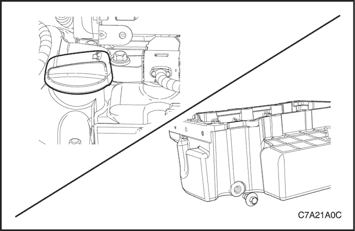
- Remove the oil filler cap for the proper oil draining.
- Remove the oil pan drain plug and drain the oil into a suitable container.


- Remove the oil pan flange-to-transaxle retaining bolts.
- Remove the transfer case mounting bracket retaining bolts. Refer to Section 5D, Transfer Case.
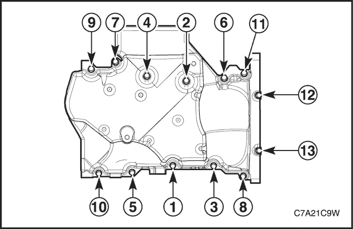


- Remove the two long bolts (12 and 13) attaching the rear of the oil pan to the crankshaft rear oil seal housing.
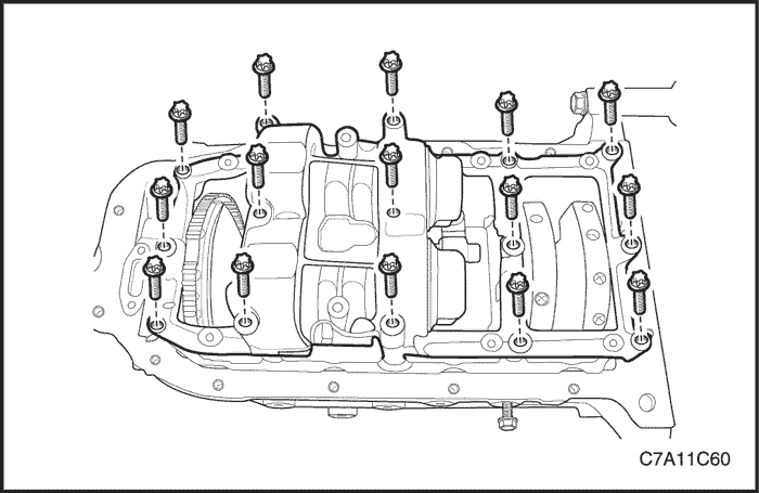
- Remove the eleven bolts (1 to 11) attaching the oil pan to the cylinder block.
- Using the shear points located at the edge of the oil pan shear the RTV sealant.
- Remove the oil pan from the cylinder block.


Disassembly
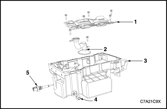
- Oil pan (3) drain plug (4) and sleeve.
- Oil level sensor (5).
- Crankshaft oil deflector bolts and remove the deflector (1).
- Oil pump suction pipe bolts and the suction pipe (2).
- Oil pump suction pipe gasket from the suction pipe and discard.
Clean
- Remove any remaining thread sealant, gasket material or sealant using a commercially available wooden or plastic scraper.
- Clean the oil pan and oil pan components in solvent.
- Clean out debris from the bolt holes.
- Dry the oil pan and oil pan components with compressed air.


Inspection
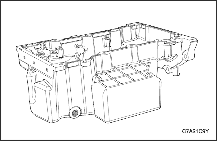
- Inspect the exterior of the oil pan for the following conditions:
- Damage to the drain plug or drain plug hole,
- Damage to the transmission mounting bosses,
- Damage to the oil level sensor threads, and
- Dents or damage to the exterior.
- Dry the oil pan and oil pan components with compressed air.
- Gouges or damage to the oil pan sealing surfaces,
- Damage to the crankshaft oil deflector,
- Damage to the bolt holes,
- Damage to the oil suction tube mounting bosses, and
- Damage to the crankshaft oil deflector mounting bosses.
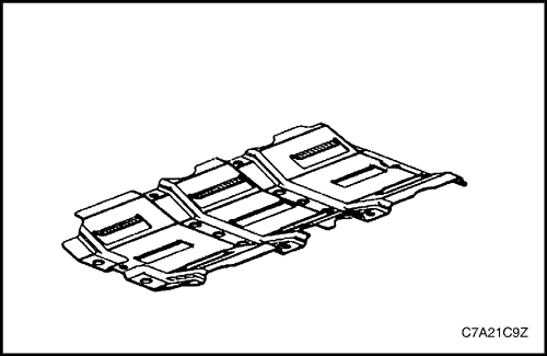


- Inspect the oil pan scraper for damage.
- Repair or replace the oil pan and/or oil pan components as required.
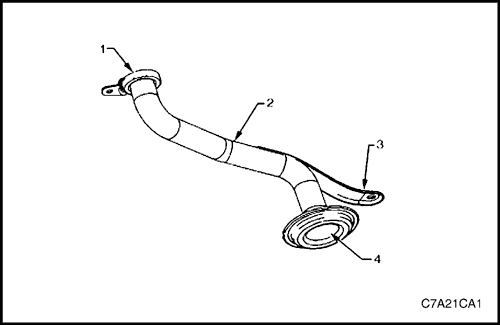


- Inspect the following:
- A. The mounting face (1) of the oil pump suction pipe for possible leakage paths.
- B. The oil pump suction pipe tube (2) for cracks, imperfections and/or damage.
- C. The oil pump pipe support bracket (3) for cracks or damage.
- D. The oil pump screen (4) for blockage, foreign material, tears, cracks and/or damage.
- Repair or replace the oil pan and/or oil pan components as required.
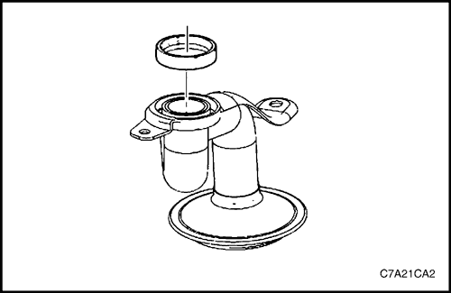


Reassembly
- Install a new oil suction tube seal onto the oil suction tube.
- Install the oil suction pipe and tighten the attaching bolts.
- Gouges or damage to the oil pan sealing surfaces,
- Damage to the crankshaft oil deflector,
- Damage to the bolt holes,
- Damage to the oil suction tube mounting bosses, and
- Damage to the crankshaft oil deflector mounting bosses.
Tighten
Tighten the oil suction pipe attaching bolt to 10 N•m (89 lb-in).
- Install the crankshaft oil deflector into the oil pan assembly and tighten the attaching bolts.
Tighten
Tighten the crankshaft oil deflector into the oil pan assembly attaching bolt to 10 N•m (89 lb-in).
- Install the oil level sensor into the oil pan assembly.
Tighten
Tighten the oil level sensor to 20 N•m (15 lb-ft).
- Install the oil pan drain plug into the oil pan assembly.
Tighten
Tighten the oil pan drain plug to 25 N•m (18 lb-ft).
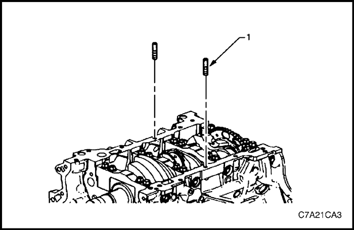


Installation Procedure
- Install the guide pins, Tool No. EN-46109 (1) into the oil pan rail bolt hole on each side of the engine block.
Tighten
Tighten the intake manifold retaining bolt and nuts to 22 N•m (16 lb-ft).
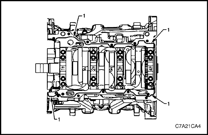


- Place a 3mm bead (1) of RTV sealant on the cylinder block pan rail and crankshaft rear oil seal housing to oil pan mating surfaces.
- Position the oil pan onto the cylinder block.
- Remove the guide pins, Tool No. EN-46109 from the cylinder block.


- Loosely install the oil pan bolts.
- Install the oil pan bolts in the sequence shown.
Tighten
- Tighten the oil pan to cylinder block attaching bolt to 23 N•m (17 lb-ft).
- Tighten the oil pan to crankshaft rear oil seal housing attaching bolt (12 - 13) to 10 N•m (89 lb-in).


- Remove the oil pan flange-to-transaxle retaining bolts.
Tighten
Tighten the oil pan flange-to-transaxle retaining bolts to 50 N•m (37 lb-ft).
- Remove the transfer case mounting bracket retaining bolts. Refer to Section 5D, Transfer Case.
- Install the front timing cover. Refer to in this section.


- Install the engine assembly. Refer to in this section.
- Install the oil pan drain plug.
Tighten
Tighten the oil pan drain plug to 25 N•m (18 lb-ft).
- Install the exhaust front pipe. Refer to Section 1G3, Engine Exhaust.
- Fill the oil pan with engine oil.
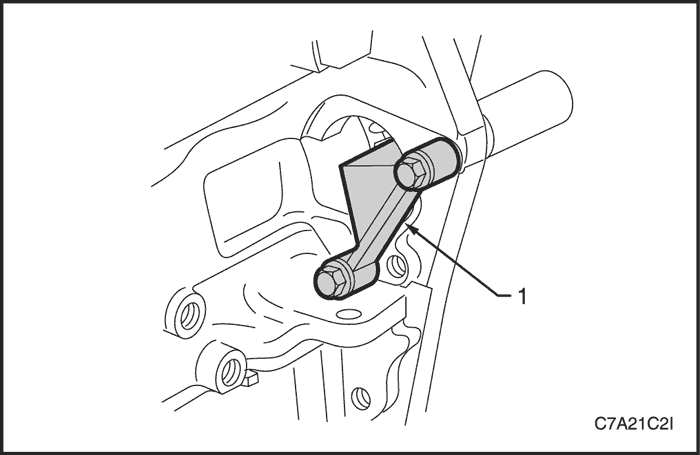


Flexplate Assembly
Removal Procedure
- Remove the engine assembly. Refer to Section 1C2, Engine Mechanical - HFV6 3.2L.
- Remove the transmission. Refer to Section 5A, AISIN 55 - 51 LE Automatic Transaxle or Section 5B, Five - Speed Manual Transaxle (D33).
- Remove the starter motor. Refer to Section 1E3, Engine Electrical - HFV6 3.2L.
- Install the flexplate holding tool, Tool No. EN-46106 (1) into the starter motor mounting location.
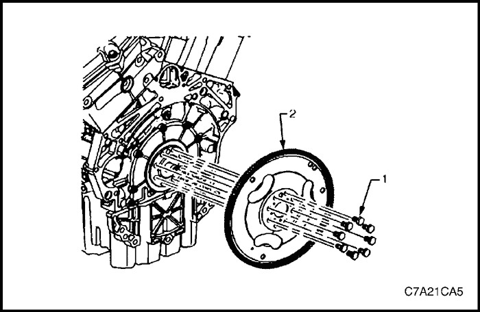


- Loosen the eight flexplate attaching bolts (1).
- Remove the flexplate holding tool.
- Using a suitable permanent marker or paint pen, mark the flexplate assembly (2) to crankshaft relationship.
- Remove the eight flexplate attaching bolts and discard.
- Remove the flexplate assembly.


Inspection
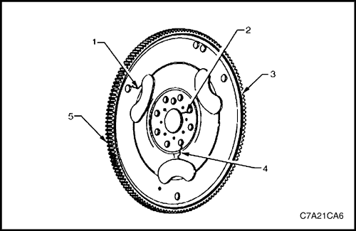
- Inspect the flexplate assembly for the following conditions:
- Stress cracks around the flexplate to torque converter mounting bolt hole locations (1).
- Stress cracks around the flexplate to crankshaft mounting bolt hole locations (2 and 4).
Caution : Do not repair the welded areas that retain the ring gear to the flexplate. The flexplate must be replaced.
- Stress cracks around the flexplate to torque converter mounting bolt hole locations (1).
- Damaged or missing ring gear teeth (5).
Note : The flexplate ring gear is not serviced separately and cannot be repaired. If found to be faulty or damaged, the flexplate assembly must be replaced.
- Replace the flexplate assembly as required.


Installation Procedure
Note : The bolt holes are unevenly spaced to enable flexplate fitment in the one position only.
- Place the flexplate assembly (2) in position on the crankshaft.
- Install new flexplate attaching bolts (1) and hand tighten.


- Install the flexplate holding tool, Tool No. EN-46106 (1) into the starter motor mounting location.
- Install the flexplate attaching bolts.
Tighten
Tighten the flexplate attaching bolt to 30 N•m (22 lb-ft) and turns the bolt another 45° using the angular torque gauge KM-470-B..
- Remove the flexplate holding tool.
- Install the starter motor. Refer to Section 1E3, Engine Electrical - HFV6 3.2L.
- Install the transmission. Refer to Section Section 5A, AISIN 55 - 51 LE Automatic Transaxle or Section 5B, Five - Speed Manual Transaxle (D33).
- Install the engine assembly. Refer to Section 1C2, Engine Mechanical - HFV6 3.2L.


Crankshaft Rear Seal And Plate Assembly
Removal Procedure
- Remove the engine assembly. Refer to "Engine Assembly" in this section.
- Remove the flexplate assembly. Refer to "Flexplate Assembly" in this section.
- Remove the engine oil pan assembly. Refer to "Oil Pan Assembly" in this section.
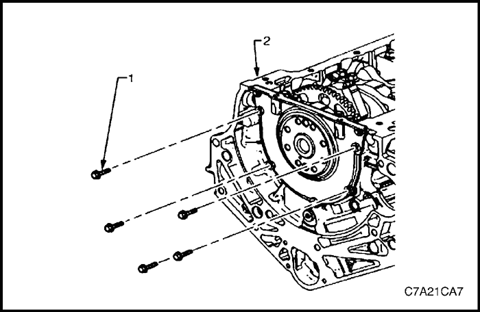
- Remove the five bolts (1) attaching the crankshaft rear seal housing to the rear of the cylinder block (2).
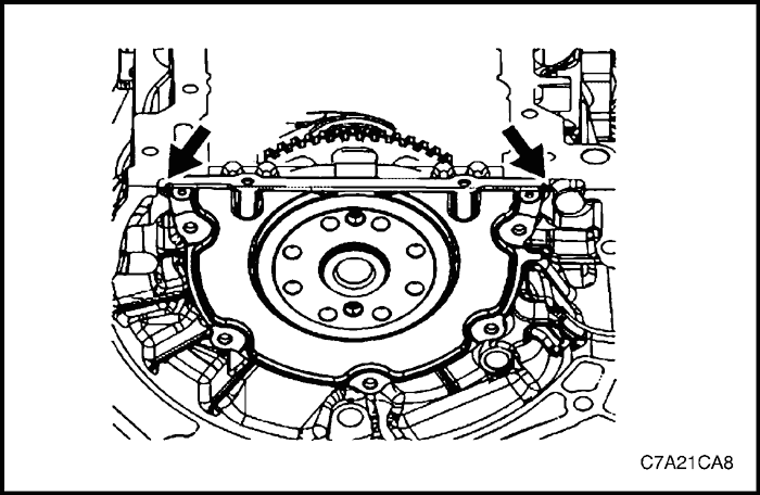


- Shear the RTV sealant using the prise points located at the edge of the crankshaft rear oil seal housing.
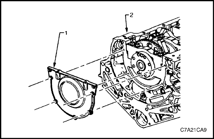


- Remove the crankshaft rear oil seal housing (1) from the cylinder block (2).


Installation Procedure
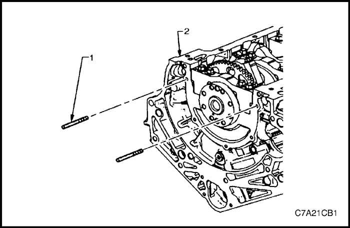
- Install the guide pins, Tool No. EN-46109 (1) into the two crankshaft rear oil seal housing bolt holes of the cylinder block (2).
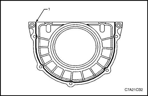


- Apply a 3mm bead (1) of RTV sealant to the crankshaft rear oil seal housing.


Note : Do not allow any engine oil onto the cylinder block mating surface, where the crankshaft rear oil seal housing is to be installed.
- Install the crankshaft rear oil seal housing (1) to the cylinder block (2).
Note : A seal-protector is provided with the new crankshaft rear seal and housing assembly. Do not remove the seal protector from the crankshaft rear oil seal housing until the crankshaft rear oil seal housing is fully in position.
- Remove the guide pins from the cylinder block.


- Install the crankshaft rear oil seal housing attaching bolts (1) to the cylinder block (2).
Tighten
Tighten the crankshaft rear oil seal housing attaching bolts to 10 N•m (89 lb-in.).
- Install the oil pan assembly. Refer to "Oil Pan Assembly" in this section.
- Install the flexplate assembly. Refer to "Flexplate Assembly" in this section.
- Install the engine assembly. Refer to "Engine Assembly" in this section.


Pistons And Connecting Rods Assembly
Removal Procedure
- Remove the engine assembly. Refer to "Engine Assembly" in this section.
- Remove both cylinder head assemblies. Refer to "Cylinder Head Assembly" in this section.
- Remove the oil pan assembly. Refer to "Oil Pan" and "Oil Pump Suction Pipe Assembly" in this section.
- Mark the top of the piston being removed to identify its specific bore.
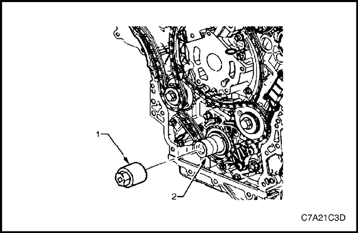
- Install Tool No. EN-46111 (1) onto the crankshaft (2).
- Rotate the crankshaft until the piston being removed is at the bottom of its stroke; bottom dead center (BDC).


Caution : If the connecting rod bearings have been used in a running engine, they must be replaced with new connecting rod bearings for reassembly.
- Before removing the connecting rods, check the connecting rod side clearance using the following procedure:
- A. Tap the connecting rod to one end of the crankshaft journal with a dead blow or wooden hammer.
- B. Using feeler gauges, measure the clearance between the crankshaft counterweight and the connecting rod.
- C. The connecting rod side clearance should not exceed specifications.
- D. If the endplay exceeds the specified limits, measure the width of the crankpin end of the connecting rod.
- E. If the connecting rod width is significantly smaller than specified and severe wear is present on the side of the connecting rod, replace the connecting rod.
- F. If the connecting rod width is within specification and excessive scoring is present on the crankshaft journals, replace the crankshaft.
Caution : Do not use a stamp, punch or any other method that may distort or stress the connecting rod and cap. Extensive engine damage may result from a connecting rod that is distorted or stressed.
- Mark the cylinder number on the connecting rod and the connecting rod cap with a paint stick or permanent marker.
Caution : Powdered metal connecting rods have rod bolts which yield when tighten to the specified torque. If the bolts are loosened or removed they must be replaced. Rod bolts that are not replaced will not torque to the correct clamp load and can lead to serious engine damage.
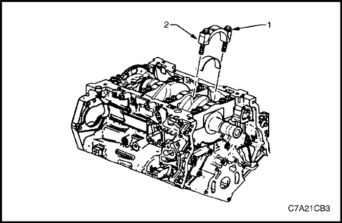
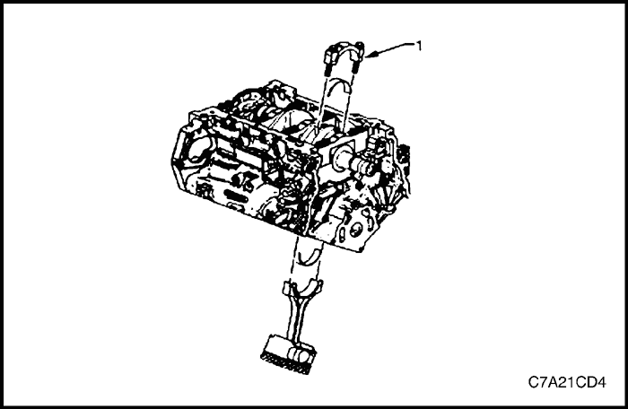
- Remove the connecting rod bolts (1), loosening progressively from side to side.
Caution : The connecting rod caps must remain with the original connecting rod.
- Remove the connecting rod cap (2).
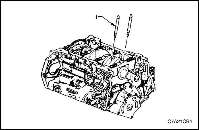


- Install connecting rod guide pin set, Tool No. EN-46121 (1) to the connecting rod bolt holes.
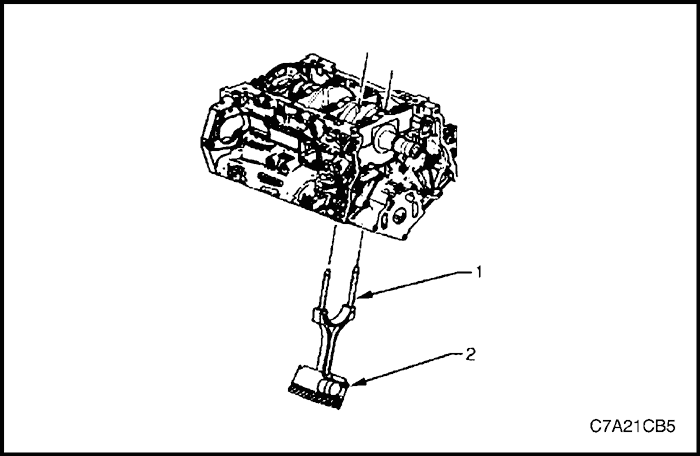


Caution : Do not damage the crankshaft journal, cylinder wall and piston cooling jets when removing the connecting rod and piston assembly.
- Using connecting rod guide pin set, Tool No. EN-46121 (1), push the connecting rod and piston assembly (2) through the top of the cylinder.
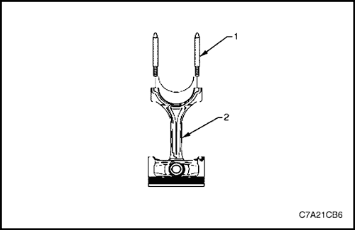


Caution : When dismantled, ensure the connecting rod, connecting rod cap, piston and bearings are organized in their original position and location. This will also aid engine mechanical diagnosis.
- Remove connecting rod guide pin set, Tool No. EN-46121 (1) from the connecting rod bolt holes.
- Remove the upper connecting rod bearing from the connecting rod (2).
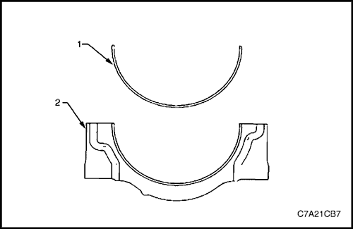


- Remove the lower connecting rod bearing (1) from the connecting rod cap (2).
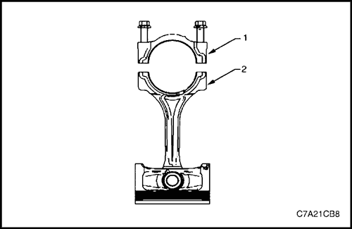


- Reattach the connecting rod cap (1) to the connecting rod (2) to prevent damage to their mating surfaces.
Note : The cap and rod are a matched set and must be kept together.
- Repeat steps 4 to 16 for the remaining piston and connecting rod assemblies.


Disassembly
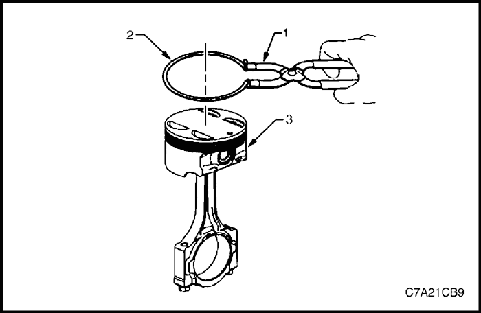
Caution : A piston ring expander must be used to remove and install the piston rings. Only expand the rings far enough to fit over the piston lands. If the rings are overexpanded, the top ring will shatter and the others will distort.
- Remove the piston rings (2) using a piston ring expander (1). Place each ring in a clean shop towel for storage.
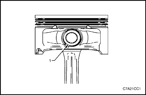


Caution : Do not reuse the piston pin retainers.
- Remove the piston pin retainers by using the removal access notch (1) in the side of the piston. Discard the piston pin retainers.
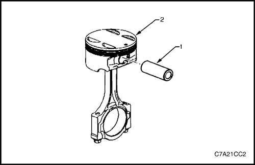


- Slide the piston pin (1) out of the piston (2). The piston will disconnect from the connecting rod.


Inspection Procedure
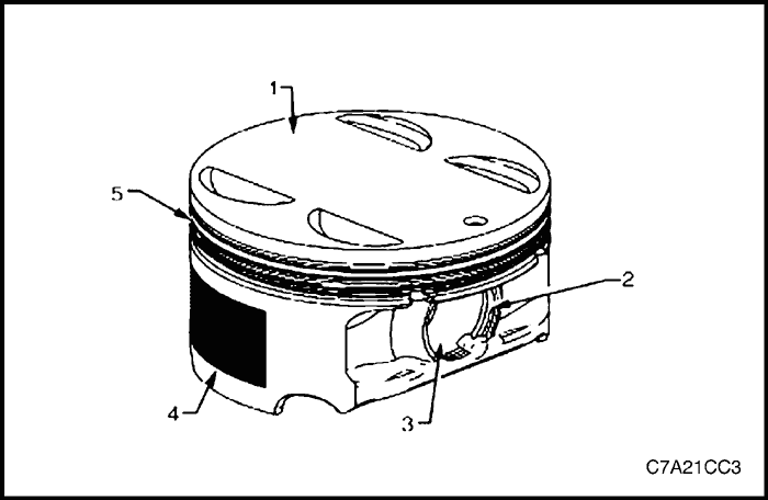
- Inspect the pistons for the following conditions.
- Eroded areas at the top of the piston (1).
- Piston pin retainer grooves for butts (2).
- Worn piston pin bores or worn piston pins (3).
- Scuffed or damaged skirt coating (4).
- Ring grooves for cracks, nicks or burrs that may cause binding (5), and
- Warped or worn ring lands
- Replace pistons that show any signs of damage or excessive wear.


- Measure the piston width using the following procedure.
- Using an outside micrometer, measure the width of the piston at the thrust surfaces of the piston, perpendicular to the piston pin centerline.
- Compare the measurement of the piston to its original cylinder by subtracting the piston width from the cylinder diameter.
- If the clearance obtained through measurement is greater than the provided specifications and the cylinder bores are within specification, replace the piston.
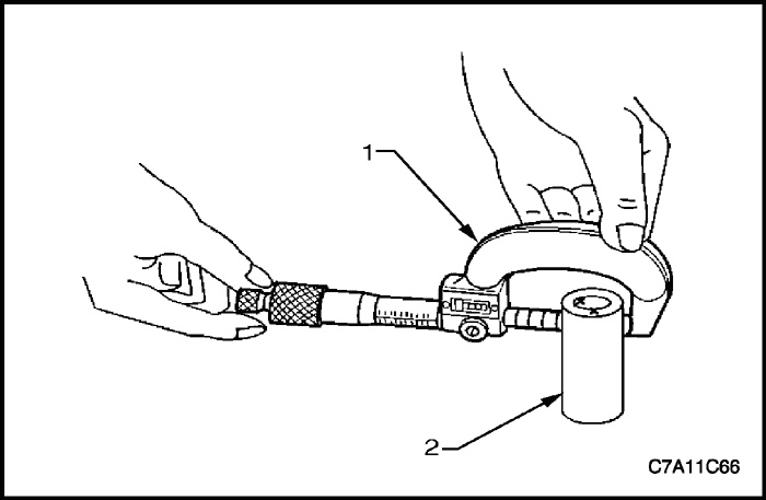


- Measure the piston pin bore to piston pin (2) clearances using the following procedure.
- Piston pin bores and pins must be free of varnish or scuffing.
- Use an outside micrometer (1) to measure the piston pin in the piston contact areas.
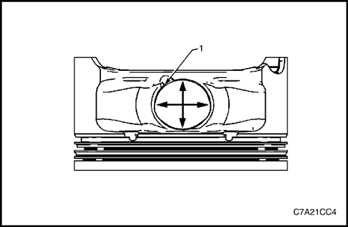


- Using an inside micrometer, measure the piston pin bore (1). Compare the result with the piston pin diameter and piston pin to piston pin bore clearance. Refer to "Engine Specifications" in this section.
- If the clearance is excessive, determine which piece is out of specification and replace as required.
- Replace the piston if any of its dimensions are out of specification.
- If the new piston does not meet clearance specifications, the cylinder block may need to be oversized to 0.25 ㎜. There is only one size of oversized pistons and rings available for service.
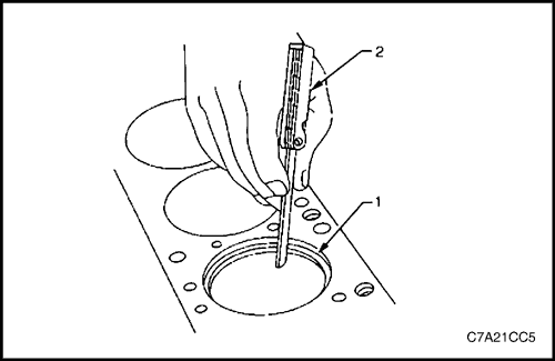


- Measure the piston ring end gap using the following procedure.
- Piston pin bores and pins must be free of varnish or scuffing.
- Place the piston ring (1) in the area of the bore where the piston ring will travel, approximately 25 mm below the deck surface. Ensure the ring is square with the cylinder bore by positioning the ring with the piston head.
- Measure the end gap of the piston ring with feeler gauges (2).
- If the clearance exceeds the provided specifications, the piston rings must be replaced.
- Repeat the procedure for all piston rings.
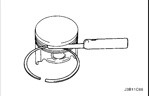


- Measure the piston ring side clearance using the following procedure.
- Roll the piston ring entirely around the piston ring groove. If any binding is caused by the ring groove, dress the groove with a fine file. If any binding is caused by a distorted piston ring, replace the ring.
- With the piston ring on the piston, use feeler gauges to check clearance at multiple locations.
- Compare the measurements with piston ring side clearance. Refer to "Engine Specifications" in this section.
- If the clearance is greater than specifications, replace the piston rings.
- If the new ring does not reduce the clearance to the correct specification, install a new piston.
- If the new piston does not meet clearance specifications, the cylinder block may need to be oversized to 0.25 mm. There is only one size of oversized pistons and rings available for service.
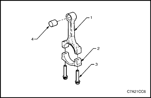


- Inspect the connecting rods for the following conditions.
- Inspect the piston pin bushing (4) for scoring or damage.
- Inspect the connecting rod beam (1) for twisting or bending.
- Inspect the rod cap (2) for any nicks or damage caused by possible interference.
- Inspect for scratches or abrasion on the rod bearing seating surface.
- If the connecting rod bores contain minor scratches or abrasions, clean the bores in a circular direction with a light emery paper.
- Retain the original bolts (3) for preliminary assembly. They must be replaced for final assembly.


- Measure the connecting rod piston pin bore to piston pin clearance using the following procedures.
- Using an outside micrometer (1), take two measurements of the piston pin (2) in the area of the connecting rod contact.


- Using an inside micrometer, measure the connecting rod piston pin bore (1).
- Subtract the piston pin diameter from the piston pin bore.
- Compare the clearance measurements. Refer to "Engine Specifications" in this section.
- If the clearance is excessive, replace the piston pin. If a new pin does not resolve the clearance problem, replace the connecting rod.


- Measure the connecting rod crankshaft bearing bore (1) using the following procedures.
- Using an inside micrometer, measure the connecting rod crankshaft bearing bore.
- Compare the bore measurements. Refer to "Engine Specifications" in this section.
- Replace the connecting rod if the bore is out of specification. Do not recondition the connecting rod.
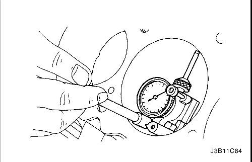


- Inspect the engine block deck surface for flatness using a straight edge and a feeler gauge. Refer to "Engine Specifications" in this section.
- Inspect the bearing bore for concentricity and alignment using cylinder bore check gauge J-8087. Refer to "Engine Specifications" in this section. If the bearing bore is beyond the specifications, replace the engine block.
- Inspect the engine block cylinder bore for wear, runout, ridging and taper using a bore gauge. Refer to "Engine Specifications" in this section.
- Inspect the engine block cylinder bore for glazing. Lightly hone the cylinder bore as necessary.


Assembly
Piston and Piston Pin
Caution : The arrow located on top of the piston must point toward the front of the engine.
Note : The connecting rod is non-directional and may be assembled/reassembled to the piston in either direction.
- Lubricate the piston pin (1) bores in the piston (2) and the connecting rod with clean engine oil.
- Assemble the piston and piston pin to the connecting rod. Correctly orient the piston when reusing a marked connecting rod.
- Align the piston pin bore with the connecting rod pin bore.
- Slide the piston pin into the piston and the connecting rod.


Caution : New piston pin retainers must be used. Never reuse the piston pin retainers.
- Install new piston pin retainers (1).
- Ensure the piston pin retainers are fully seated in their grooves.
- Repeat steps 1 to 6 for the remaining pistons.
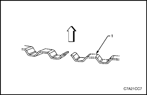


Piston Ring
- Correctly orient the oil control ring expander (1) before installation. The ends of the expander must be facing toward the top of the piston.
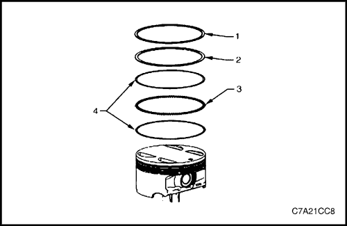


- Using a piston ring expander, install the oil control ring assembly using the following procedure:
- a. Install the expander ring (3).
- b. Install the two oil scraper rings (4). Expand the rings only enough to clear the piston diameter. Over-expanding the piston rings will distort or crack the rings.
- Install the second (2) and top (1) piston rings as follows.


- Using the ring expander (1), install the second (2) piston ring (2) onto the piston (3). Do not over-expand the ring. Repeat for the top ring.
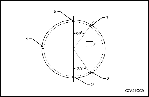


- Once the rings are installed, set the ring gaps for the oil control, second and top ring as follows. Use the piston location arrow for reference.
- Lower oil control ring position (1).
- Upper oil control ring position (2).
- Top ring position (3).
- Oil control ring expander position (4).
- Second ring position (5).
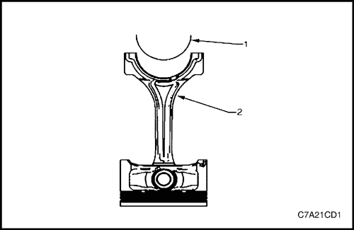


Connecting Rod Bearing
Caution : If the connecting rod bearings have been used in a running engine, they must be replaced with new connecting rod bearings for reassembly.
- Clean the connecting rod (2) and the connecting rod cap bearing bore with a lint-free cloth.
- Clean the oil from behind the connecting rod bearing halves.
- Install a new upper connecting rod bearing (1) into position. Roll the bearing into position so the lock tang engages the alignment slot. The bearing must fit flush in the connecting rod.


- Install the lower connecting rod bearing (1) into position in the connecting rod cap (2).
- Roll the bearing into position so the lock tang engages the alignment slot. The bearing must fit flush with the connecting rod cap.


Installation Procedure
Piston Connecting Rod and Connecting Rod Bearing Installation
- Liberally lubricate the cylinder walls, piston rings and piston skirts with engine oil.
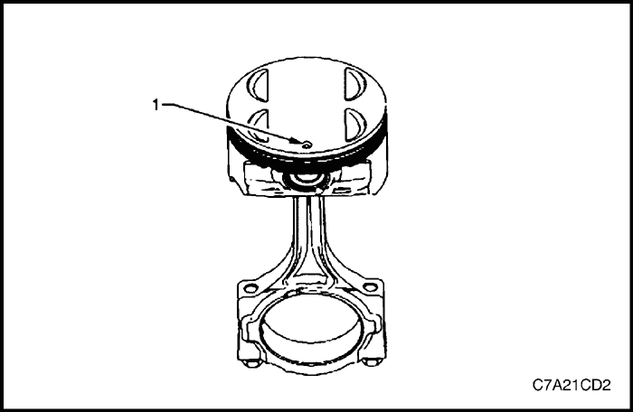
Caution : The piston is directional and must be installed in the engine block in the correct direction. The locating arrow on the top of each piston must be pointing toward the front of the engine.
- Select the correctly numbered piston/connecting rod assembly for the cylinder. A dot (1) showing correct piston orientation is located on the top of the piston.
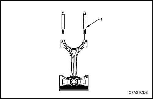


- Install connecting rod guide pin set, Tool No. EN-46121 (1) into the connecting rod bolt holes.


- Compress the piston rings using a commercially available ring compressor.
Caution : Extreme care must be used when installing the piston and connecting rod to ensure the rod does not scrape or nick the cylinder bore, oil jets, or crankshaft surfaces.
- Using both hands from the top and bottom of the cylinder, slowly guide the piston (2) and connecting rod assembly into the cylinder. Do not allow the connecting rod to contact the cylinder wall.
- When the ring compressor contacts the deck surface, gently tap the piston into the cylinder using the handle end of a dead-blow hammer. Guide the connecting rod onto the crankshaft bearing journal using connecting rod guide pin set, Tool No. EN-46121 (1) while gently tapping the piston into the cylinder with a soft-blow hammer.


- Remove connecting rod guide pin set, Tool No. EN-46121 (1) from the connecting rod bolt holes.


Connecting Rod Bearing Clearance Measurement
Note : Before final assembly, check the clearance of the new connecting rod bearings.
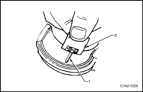
- Place a length of fresh, room temperature plastic gauging material all the way across the connecting rod bearing journal.
- Install the connecting rod bearing into the connecting rod cap.
- Install the connecting rod end cap (1) on its original connecting rod and ensure the bearing lock tangs are aligned on the same side of the rod.


Note : Reuse the old connecting rod bolts only for measuring the connecting rod bearing clearance.
- Install the connecting rod cap bolts into the connecting rod cap.
Tighten
Tighten the connecting rod cap bolts to 30 N•m (22 lb-ft) and loosen the bolts completely. Tighten the connecting rod cap bolts to 25 N•m (18 lb-ft) again, and turns the bolt another 110° using the angular torque gauge KM-470-B.
- Allow the assembly to sit for at least 2 minutes.
- Remove the connecting rod cap bolts and discard.
- Remove the connecting rod cap.
- Determine the connecting rod bearing clearance by comparing the width of the flattened plastic gauging (1) material at its widest point with the graduation on the gauging material container (2).
- Compare the measurements with the specifications.
- If the new bearings do not provide the correct crankshaft to connecting rod bearing clearance, inspect the following:
- a. Measure the crankshaft connecting rod journals for the correct specified size and ensure the correct new bearings are being installed. If the crankshaft connecting rod journals are incorrectly sized, replace or regrind the crankshaft. Crankshaft machining is permitted and undersized bearings are available.
- b. Measure the connecting rod bearing bore diameter to ensure correct size. The connecting rod is not machineable and the connecting rod must be replaced if out of specification.
- Clean the plastic gauging material from the connecting rod bearing journals using a soft lint-free cloth.


Connecting Rod Final Assembly Procedure
- Carefully guide the connecting rod away from the crankshaft connecting rod journal slightly to lubricate the crankshaft connecting rod bearing journal.
- Apply a liberal amount of clean engine oil to the crankshaft connecting rod bearing journal.
- Guide the connecting rod to the crankshaft connecting rod journal.
- Install the connecting rod end cap (1) on its original connecting rod and ensure the bearing lock tangs are aligned on the same side of the rod.
Caution :
- Do not lubricate the new connecting rod bolts. The new bolts have a pre-applied graphite lubricant. Applying lubricant to the connecting rod bolts will effect the clamp load when the connecting rod bolts are tightened to the specified torque. Incorrect clamp load can lead to component failure and extensive engine damage.
- Do not reuse the old connecting rod bolts.
- Install new connecting rod bolts into the connecting rod cap.
Tighten
Tighten the connecting rod cap bolts to 30 N•m (22 lb-ft) and loosen the bolts completely. Tighten the connecting rod cap bolts to 25 N•m (18 lb-ft) again, and turns the bolt another 110° using the angular torque gauge KM-470-B.
Note : During and after installation, ensure each piston is positioned correctly in the correct cylinder. The locating arrow on the top of each piston must be pointing toward the front of the engine.
- Repeat these procedures for the remaining piston/connecting rod assemblies.
- Reinstall the oil pan and oil pump pick up assembly. Refer to "Oil Pan" and "Oil Pump Suction Pipe Assembly" in this section.
- Reinstall the cylinder heads. Refer to "Cylinder Head Assembly" in this section.
- Reinstall the engine assembly. Refer to "Engine Assembly" in this section.


Cylinder Block
Disassembly
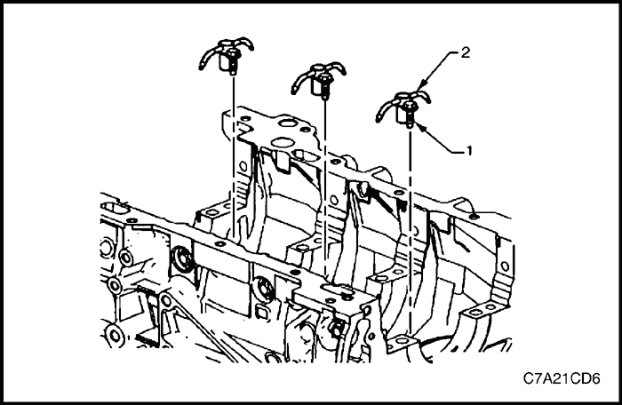
- Remove oil jet bolt (1) attaching the oil jet (2), three places.
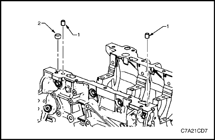


- Remove the cylinder block-to-oil pan alignment dowels (1) and the bank 1 side front oil pan rail oil gallery expansion plug (2).
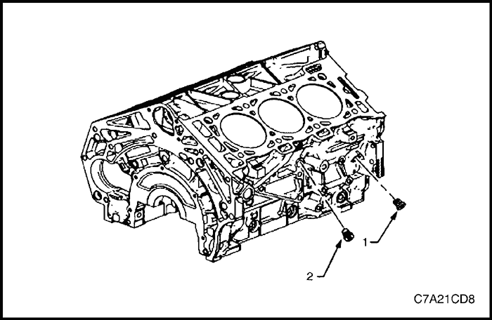


- Remove the bank 1 side oil gallery threaded plug (1) and coolant drain threaded plug (2).
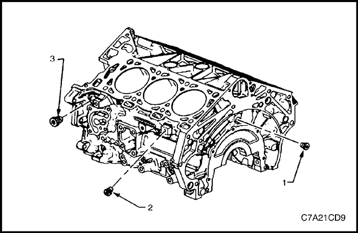


- Remove the rear oil gallery threaded plug (1), the bank 2 side coolant drain threaded plug (2) and the left-hand side oil gallery threaded plug (3).
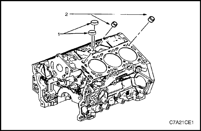


Caution : Do not force coolant expansion plugs downwards during removal procedure as the cylinder block will be damaged.
- Remove the coolant expansion plugs (1) and the cylinder block-to-cylinder head alignment dowels (2).
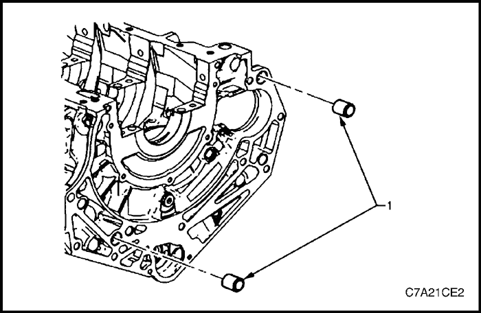


- Remove the cylinder block-to-transmission alignment dowels (1).
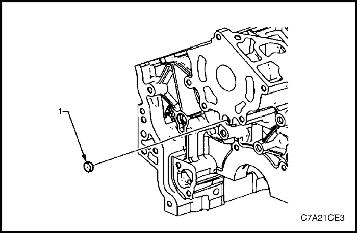


- Remove the front oil gallery expansion plug (1).
Clean
- Remove all thread sealant, gasket material or sealant using a commercially available plastic or wood scraper.
- Clean all the following areas with a suitable solvent:
- sealing surfaces,
- cooling passages,
- oil passages, and
- bearing journals.
- Clean all threaded and through holes with a suitable solvent.
- Dry the engine block with compressed air.


Inspection
Measuring Cylinder Bore Diameter
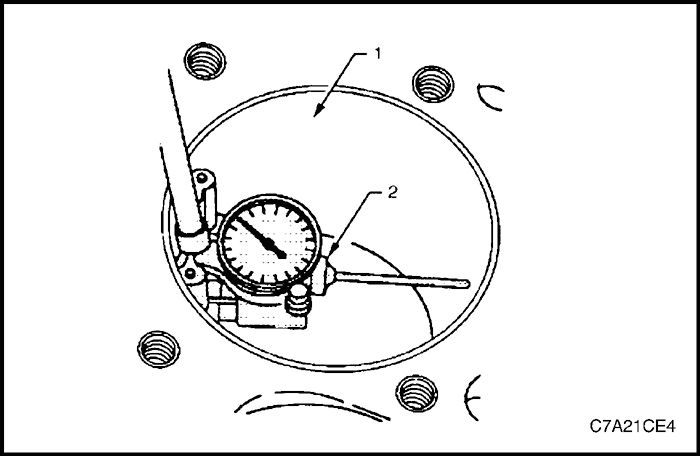
- Measure the cylinder bore diameter 37 mm from the deck face (1) using a commercially available bore gauge or Tool No. J-8087 (2).
- Record the results and compare with the dimensions listed in the specifications.
Note : If the cylinder diameter exceeds the specifications, the cylinder block may be oversized to 0.25 mm. Only one size of oversized pistons and rings are available for service. If the cylinder bore diameter exceeds specification by more than 0.25 mm, the cylinder block must be replaced.
Measuring Cylinder Bore Taper
- Measure the cylinder bore along the thrust surfaces, perpendicular to the crankshaft centerline, at 10 mm below the deck surface and record the measurement.
- Measure the cylinder bore along the thrust surfaces, perpendicular to the crankshaft centerline, at 100 mm below the deck surface and record the measurement.
- Calculate the difference between the two measurements. The result will be the cylinder taper.
- Compare the results with the dimensions listed in the specifications.
- If the cylinder diameter exceeds the specifications, the cylinder block may be oversized to 0.25 mm. Only one size of oversized pistons and rings are available for service. If the cylinder bore diameter exceeds specification by more than 0.25 mm, the cylinder block must be replaced.
Measuring Cylinder Bore Out-of-Round
- Measure both the thrust and non-thrust cylinder diameter at 10 mm below the deck. Record your measurements.
- Calculate the difference between the two measurements. The result will indicate out-of-round at the upper end of the cylinder.
- Measure both the thrust and non-thrust cylinder diameter at 100 mm below the deck surface. Record your measurements.
- Calculate the difference between the two measurements. The result will indicate out-of-round at the lower end of the cylinder.
- Compare your results with the dimensions listed in the specifications.
- If the cylinder diameter exceeds the specifications, the cylinder block may be oversized to 0.25 mm. Only one size of oversized pistons and rings are available for service. If the cylinder bore diameter exceeds specification by more than 0.25 mm, the cylinder block must be replaced.


Deck Flatness Inspection
- Ensure the engine block decks are clean and free of gasket material.
- Inspect the surface for any imperfections or scratches that could inhibit correct cylinder head gasket sealing.
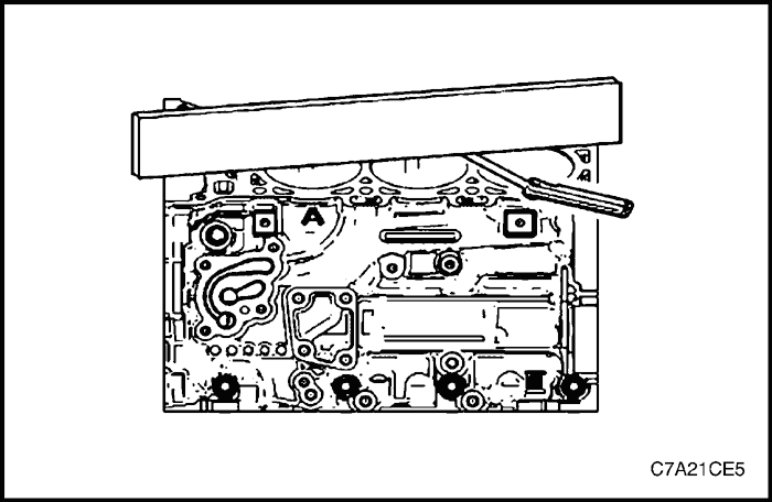
- Place a straight-edge diagonally across the cylinder block deck face surface.
- Measure the clearance between the straight-edge and the cylinder block deck face using a feeler gauge at 4 points along the straight-edge.
- If the warpage is less than 0.05 mm, the cylinder block deck surface does not require resurfacing.
- If the warpage is between 0.05 ±0.20 mm or any imperfections or scratches that could inhibit correct cylinder head gasket sealing are present, the cylinder block deck surface requires resurfacing.
- If resurfacing is required the maximum amount that can be removed is 0.25 mm.
- If the cylinder block deck surface requires more than 0.25 mm material removal the block must be replaced.


Reassembly
- Place RTV sealant on new coolant expansion plugs (1) and install the new coolant expansion plugs.
- Install the cylinder block-to-cylinder head alignment dowels (2).


- Install a new front oil gallery expansion plug (1).


- Install the cylinder block-to-transmission alignment dowels (1).


- Install the rear oil gallery threaded plug (1), bank 2 side coolant drain threaded plug (2) and the left-hand side oil gallery threaded plug (3).
Tighten
- Tighten the cylinder block rear oil gallery threaded plug to 31 N•m (33 lb-ft).
- Tighten the bank 2 side coolant drain threaded plug to 31 N•m (23 lb-ft).
- Tighten the bank 2 side oil gallery threaded plug to 31 N•m (23 lb-ft).


- Install the oil gallery threaded plug (1) and the right-hand side coolant drain threaded plug (2).
Tighten
- Tighten the bank 1 side oil gallery threaded plug to 31 N•m (23 lb-ft).
- Tighten the bank 1 side coolant drain threaded plug to 31 N•m (23 lb-ft).


- Install the new bank 1 side front oil pan rail oil gallery expansion plug (1) and the cylinder block-to-oil pan alignment dowels (2).


- Install the oil jet (2), three places.
- Install the oil jet attaching bolt (1), three places.
Tighten
Tighten the oil jet attaching bolt to 10 N•m (89 lb-in).
 | |  | |
| © Copyright Chevrolet Europe. All rights reserved |


