UNIT REPAIR


Cylinder Head and Valve Train Components
Disassembly
Caution : Ensure valve heads will not contact anything during the following step in order to avoid bending or damage.
- Remove the cylinder head assembly. Refer to "Cylinder Head Assembly" in this section.
- Using an appropriately sized deep socket (1) and a plastic hammer (2), lightly tap on the valve spring retainer to loosen the valve collets.
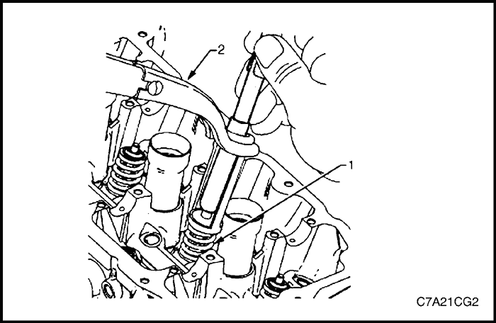


Compressed valve springs (1) have high tension against the valve spring compressor (2). Valve springs that are not correctly compressed by, or are released from the valve spring compressor can be ejected from the valve spring compressor with intense force. Use care when compressing or releasing the valve spring with the valve spring compressor and when removing or installing the valve stem keys. Failing to use care may cause personal injury.
Caution : Do not compress the valve springs less than 24.0 mm. Contact between the valve spring retainer and the valve stem oil seal can cause potential valve stem oil seal damage.
- Compress the valve spring (1) using valve spring compressor Tool No. J-8062 (2) and adaptor Tool No. EN-46119.
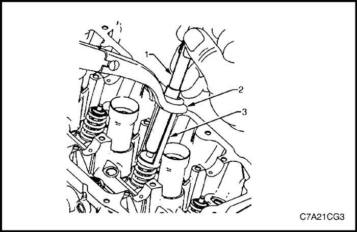


- Remove the valve collets using Tool EN-46117 (1).
- Remove the valve spring compressor (2) and the adapter (3).
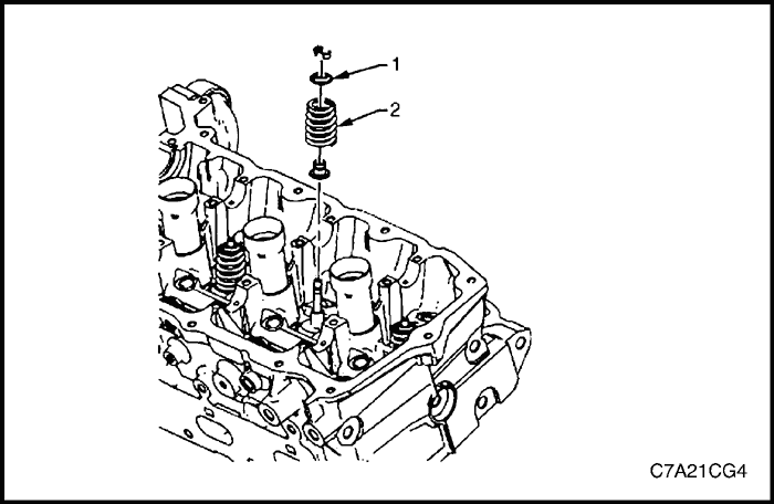


- Remove the valve spring retainer (1).
- Remove the valve spring (2).
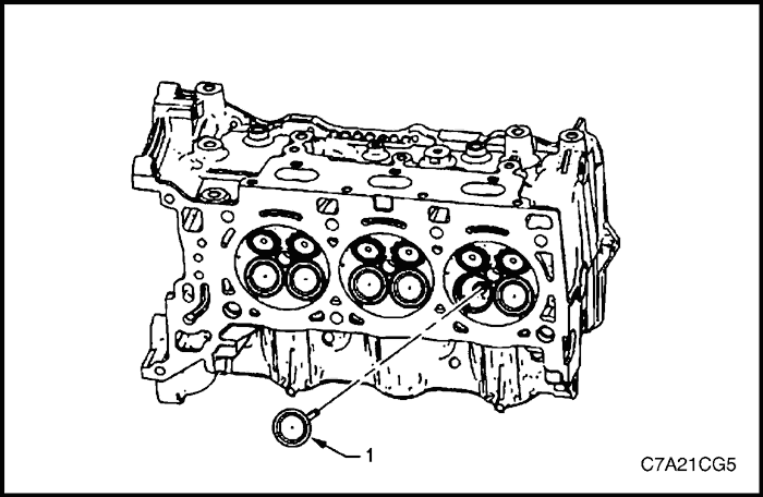


- Remove the valves (1).


Caution : Never reuse a valve stem oil seal.
- Remove the valve stem oil seal using Tool No. EN-46116 and discard.
- Repeat these procedures for the remaining valves.


- Remove the cylinder head oil gallery expansion plugs (1).
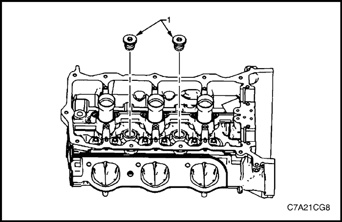


- Remove the cylinder head coolant threaded plugs (1).
Clean
Caution : Due to the aluminium alloy construction of the cylinder head, wire brushes and steel scrapers must not be used during the cleaning process, as damage to sealing surfaces may occur. Use a wood or plastic scraper as an alternative.
- Remove any old thread sealant, gasket material or sealant using commercially available plastic or wooden scraper.
- Clean all cylinder head surfaces with non-corrosive solvent.
- Blow out all the oil galleries using compressed air.
- Remove any carbon deposits from the combustion chambers.
- Clean any debris or build-up from the lifter pockets.


Inspection
Visual Inspection
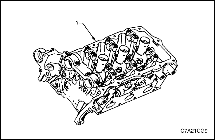
- Inspect the cylinder head (1) camshaft bearing surfaces for the following conditions:
- excessive scoring or pitting,
- discoloration from overheating, and
- deformation from excessive wear.
- If any of the above conditions exist on the camshaft bearing surfaces, replace the cylinder head. Do not machine the camshaft bearing journals.


- Inspect the cylinder head for the following:
- Cracks, damage or pitting in the combustion chambers.
- Debris in the oil galleries. continue to clean the galleries until all debris is removed.
- Coolant leaks or damage to the deck face sealing surface. if coolant leaks are present, measure the surface warpage.
- Burrs or any defects that would degrade the sealing of a new secondary camshaft chain tensioner gasket.replace the cylinder head. Do not machine the camshaft bearing journals.
- Damage to any gasket surfaces.
- Damage to any threaded bolt holes.
- Burnt or eroded areas in the combustion chamber.
- Cracks in the exhaust ports and combustion chambers.
- External cracks in the water passages.
- Restrictions in the intake or exhaust passages.
- Restrictions in the cooling system passages.
- Rusted, damaged or leaking core plugs.
- If the cylinder head is cracked or damaged, it must be replaced. No welding or patching of the cylinder head is recommended.
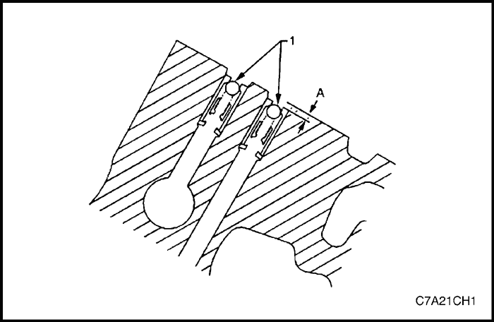
- Inspect the camshaft position actuator oil feed check valves (1) to ensure they are correctly positioned in the cylinder head. The camshaft position actuator oil feed check valve should be flush to 2 mm below the cylinder head deck surface (A).
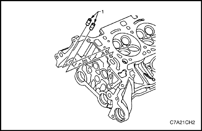


- Damaged, restricted or clogged check valves (1) can be replaced using the camshaft position actuator check-ball remover/installer, Tool No. EN-46122.
Cylinder Head Measurement
Camshaft Journal Clearance
- Install the camshaft bearing cap in the cylinder head without the camshaft.
- Install the camshaft cap bolts and tighten the bolts to 10 N•m (89 lb-in).
- Measure the camshaft bearings using an inside micrometer.
- Subtract the camshaft journal diameter from the camshaft bearing diameter. This will provide the running clearance. If the running clearance exceeds specifications and the camshaft journals are within specification, replace the cylinder head.
Camshaft Journal Alignment
- Inspect the cylinder head camshaft bearing surfaces for any imperfections or scratches that could inhibit correct camshaft clearances. Repair minor imperfections or scratches.
- Install the camshafts in the cylinder head.
- Install the camshaft bearing caps.
- Install the camshaft cap bolts and tighten the bolts to 10 N•m (89 lb-in).
- Ensure the camshafts spin freely in the cylinder head. If the camshaft does not run freely, replace the cylinder head.
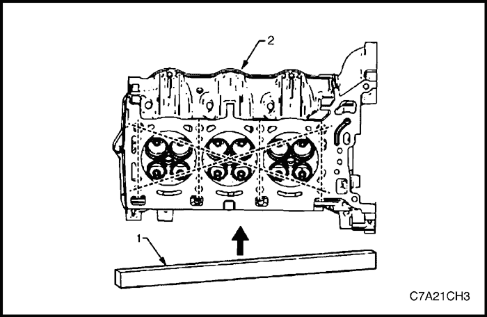


Deck Flatness Inspection
- Ensure the cylinder head decks are clean and free of gasket material.
- Inspect the surface for any imperfections or scratches that could inhibit correct cylinder head gasket sealing.
- Place a straight-edge (1) diagonally across the cylinder head (2) deck face surface.
- Measure the clearance between the straight-edge and the cylinder head deck face using a feeler gauge at four points along the straight-edge.
- If the warpage is less than 0.05 mm, the cylinder head deck surface does not require resurfacing.
- If the warpage is between 0.05±0.20 mm or any imperfections or scratches that could inhibit correct cylinder head gasket sealing are present, the cylinder head deck surface requires resurfacing.
- If resurfacing is required the maximum amount that can be removed is 0.25 mm.
- If the cylinder head deck surface requires more than 0.25 mm material removal the head must be replaced.
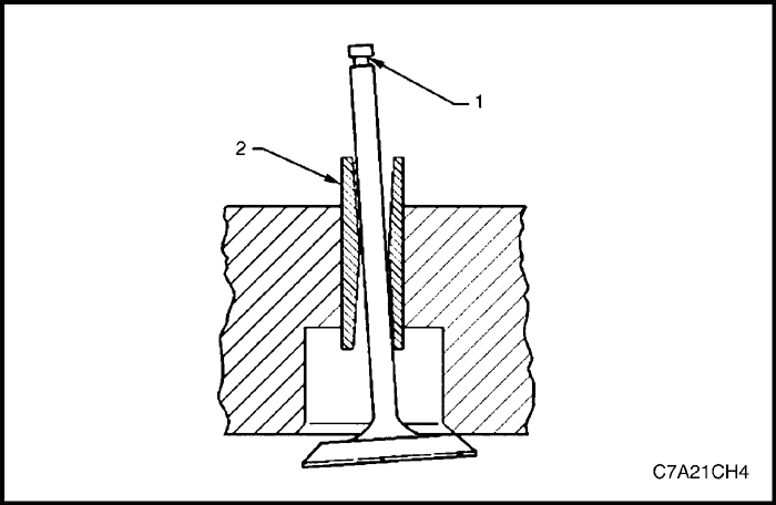


Valve Guide Measurement
- Measure the valve stem (1) to-guide (2) clearance. Excessive valve stem-to-guide clearance may cause excessive oil consumption and may also cause a valve to break. Insufficient clearance will result in noisy and sticky functioning of the valve and will disturb the engine assembly smoothness.
- Clamp a dial indicator to the cylinder head at the camshaft cover rail.
- Locate the dial indicator so the movement of the valve stem from side to side, crossways to the cylinder head, will cause a direct movement of the indicator stem. The dial indicator stem must contact the side of the valve stem just above the valve guide.
- Drop the valve head about 0.064 mm off the valve seat.
- Use light pressure when moving the valve stem from side to side to obtain a clearance reading.
- If the clearance for the valve is greater than specified and a new standard diameter valve stem will not bring the clearance within specifications, the valve guide may be oversized by 0.075 mm using the valve guide reamer, Tool No. J 42096 or by 0.375 mm using the valve guide reamer, Tool No. EN-46120. Two sizes of oversized valve stems are available for service.
- Valve guide wear at the bottom 10 mm of the valve guide is not significant enough to affect normal operation.
- If over sizing the guide does not bring the clearance within specifications, replace the cylinder head.
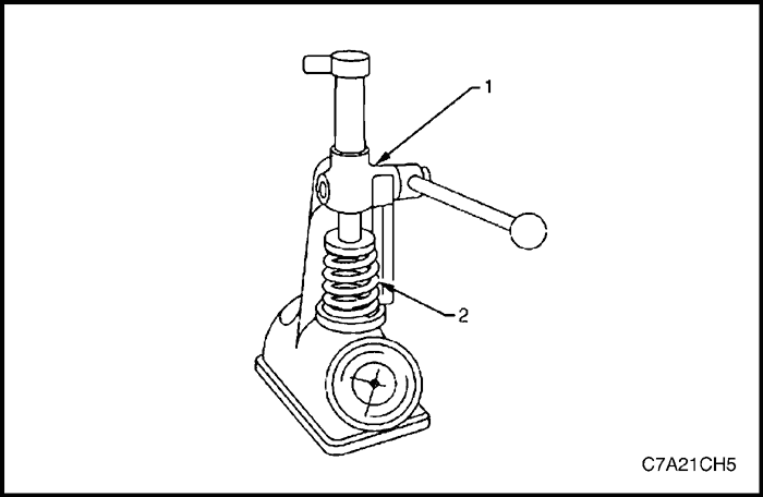


Valve Spring Inspection and Measurement
- Measure the valve stem (1) to-guide (2) clearance. Excessive valve stem-to-guide clearance may cause excessive oil consumption and may also cause a valve to break. Insufficient clearance will result in noisy and sticky functioning of the valve and will disturb the engine assembly smoothness.
- Clamp a dial indicator to the cylinder head at the camshaft cover rail.
- Locate the dial indicator so the movement of the valve stem from side to side, crossways to the cylinder head, will cause a direct movement of the indicator stem. The dial indicator stem must contact the side of the valve stem just above the valve guide.
- Drop the valve head about 0.064 mm off the valve seat.
- Use light pressure when moving the valve stem from side to side to obtain a clearance reading.
- If the clearance for the valve is greater than specified and a new standard diameter valve stem will not bring the clearance within specifications, the valve guide may be oversized by 0.075 mm using the valve guide reamer, Tool No. J 42096 or by 0.375 mm using the valve guide reamer, Tool No. EN-46120. Two sizes of oversized valve stems are available for service.
- Valve guide wear at the bottom 10 mm of the valve guide is not significant enough to affect normal operation.
- If over sizing the guide does not bring the clearance within specifications, replace the cylinder head.
Inspection
- Clean the valve springs in solvent.
- Dry the valve springs with compressed air.
- Inspect the valve springs for broken coils or coil ends.
Measurement
- Use a commercially available valve spring tester to measure the valve spring tension.
Caution : Do not use shims to increase spring load. The use of shims can cause the valve spring to bottom out before the camshaft lobe is at peak lift.
- If low valve spring load is found, replace the valve springs.
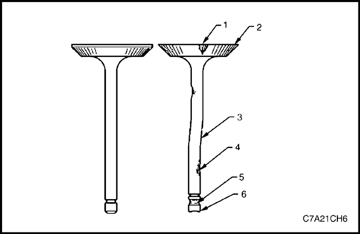


Valve and Seat Grinding
Valve Cleaning
Caution : Do not use a wire brush on any part of the valve stem. The valve stem is chrome plated to provide enhanced wear characteristics. Wire brushing the stem could remove the chrome plating.
- Use soft bristle brush to clean any carbon build-up from the valve head.
- Thoroughly clean the valve with solvent and wipe dry.
Valve Visual Inspection
- Inspect the valve for damage from the head to tip for the following conditions:
- pitting in the valve seat area (1),
- lack of valve margin (2),
- bending in the valve stem (3),
- pitting or excessive wear in the stem (4),
- worn valve key grooves (5), and
- worn valve tip (6).
- Replace the valve if any of these conditions exist.
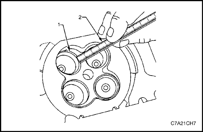


Valve Seat Width Measurement
- Measure the valve seat (1) width in the cylinder head using a scale (2).
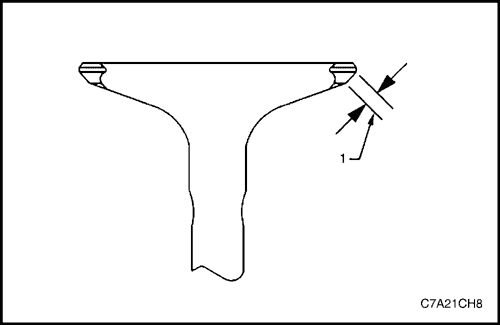


- Measure the seat width on the valve face (1) using a correct scale.
Caution : The seat contact area must be at least 0.5 mm from the outer diameter (margin) of the valve. If the contact area is too close to the margins, the seat must be reconditioned to move the contact area away from the margin.
- If the seat widths are acceptable, check the valve seat roundness.
- If the seat width is not acceptable, grind the valve seat to bring the width back to specification. Correct valve seat width is critical to providing the correct amount of valve heat dissipation.
Valve Seat Roundness Measurement
- Measure the valve seat roundness using a dial indicator attached to a tapered pilot installed in the guide. The pilot should have a slight bind when installed in the guide.
Caution : The correct size pilot must be used. Do not use adjustable diameter pilots. Adjustable pilots may damage the valve guides.
- If the valve seat exceeds the roundness specification, grind the valve and valve seat.
- If new valves are being used, the valve seat roundness must be within 0.05 mm.
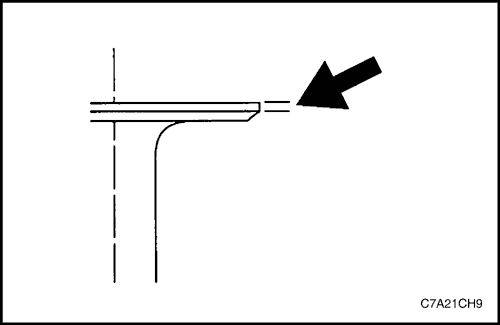


Valve Margin Measurement
- Measure the valve margin using an appropriate scale.
- If the valve margins are beyond specification, replace the valves.
- If the valve margins are within specification and do not require refacing, test the valve for seat concentricity.


Valve-to-Seat Concentricity Measurement
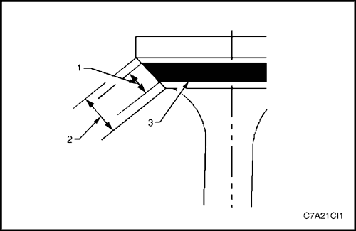
Checking the valve-to-seat concentricity determines whether the valve and seat are sealing correctly.
Measure the valve face and the valve seat to ensure correct valve sealing.
- Coat the valve face lightly with blue dye (3).
- Install the valve in the cylinder head.
- Turn the valve against the seat with enough pressure to wear off the dye.
- Remove the valve from the cylinder head.
- If the valve face is concentric, providing a correct seal, with the valve stem, a continuous mark (1) will be made around the entire face (2).
Caution : The wear mark must be at least 0.5 mm from the margin of the valve. If the wear mark is too close to the margin, the seat must be reconditioned to move the contact area away from the margin.
- If the face is not concentric with the stem, the mark will not be continuous around the valve face. The valve should be refaced or replaced and the seat must be reconditioned.


Valve and Seat Reconditioning Procedure
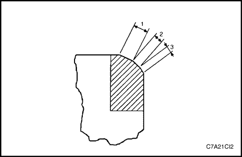
If the valve seat width, roundness or concentricity are beyond specifications, grind the seats in order to ensure correct heat dissipation and prevent the build up of carbon on the seats.
If valve seat reconditioning is required, reface the valve face, unless a new valve is used.
- Grind the valve seats (2) to the correct angle specification.
- Using the correct angle specification, grind and relieve the valve seats (1) to correctly position the valve seating surface (2) to the valve.
- Using the correct angle specification, grind and undercut the valve seats (3) to narrow the valve seat widths to the specifications.
- If the original valve is being used, grind the valve to the specifications. Measure the valve margin again after grinding. Replace the valve if the margin is out of specification. New valves do not require grinding.
- When grinding the valves and seats, grind off as little material as possible. Cutting valve seat results in lowering the valve spring pressure.
- Install the valve in the cylinder head.
Caution : If using refaced valves, lap the valves into the seats with a fine grinding compound. The refacing and reseating operations should leave the refinished surfaces smooth and true so that minimal lapping is required. Excessive lapping will groove the valve face and prevent a good seat when hot.
Note :
- Clean any remaining lapping compound from the valve and seat with solvent and compressed air prior to final assembly.
- If fitting new valves, do not lap the valves under any condition.
- After obtaining the correct valve seat width in the cylinder head, measure the valve stem height.
- If the valve stem height is acceptable, test the seats for concentricity.


Valve Stem Height Measurement Procedure
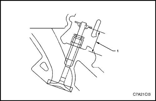
Caution : To determine the valve stem height measurement, measure from the valve spring seat to the valve spring retainer.
- Install the valve into the valve guide.
- Ensure the valve is seated to the valve seat.
- Install the valve stem oil seal.
- Install the valve spring retainer and valve stem keys.
- Measure the distance (1) between the cylinder head to the bottom of the valve spring retainer.
- If the maximum height specification is exceeded, a new valve should be installed and the valve stem height re-measured.
Caution :
- Do not grind the valve stem tip. The tip of the valve is hardened and grinding the tip will eliminate the hardened surface causing premature wear and possible engine damage.
- Do not use shims to adjust valve stem height. The use of shims will cause the valve spring to bottom out before the camshaft lobe is at peak lift and engine damage could result.
- If the valve stem height still exceeds the maximum height specification, the cylinder head must be replaced.


Assembly
- Install the cylinder head coolant threaded plugs (1).
Tighten
Tighten the cylinder head coolant threaded plugs to 31 N•m (23 lb-ft).


- Install the cylinder head oil gallery expansion plugs (1).


Caution : Never reuse a valve stem oil seal. Always use new seals when assembling the cylinder head.
- Fit the valve stem oil seals onto the guides using Tool No. EN-46116 (1).
Caution : Force should only be applied to the valve spring contact area of the new valve stem oil seal during installation.
- Push and twist the valve stem oil seal into position on the valve guide until the seal positively locks on the guide using Tool No. EN-46116.
- Lubricate the valve stem and valve guide ID with clean engine oil.


Caution : The valve stem oil seal must not come loose from the valve guide when the valve (1) is installed.
- Insert the valve into the valve guide until it bottoms on the valve seat.


- Position the valve spring (2) on the spring seat (1).
- Place the valve spring retainer onto the valve spring.


Compressed valve springs (1) have high tension against the valve spring compressor (2). Valve springs that are not correctly compressed by, or are released from, the valve spring compressor can be ejected from the valve spring compressor with intense force. Use care when compressing or releasing the valve spring with the valve spring compressor and when removing or installing the valve stem keys. Failing to use care may cause personal injury.
Caution : Do not compress the valve springs less than 24.0 mm. Contact between the valve spring retainer and the valve stem oil seal can cause potential valve stem oil seal damage.
- Compress the valve spring using valve spring compressor Tool No. J-8062 and adaptor Tool No. EN-46119.
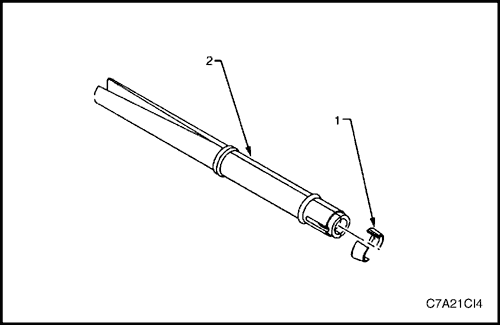


Caution : Ensure correct directional placement of valve collets (1) in Tool No. EN-46117 (2). The valve collets must be installed with the tapered end towards the valve stem seal.
- With the spring compressed, install the valve collets into Tool No. EN 46117.


- Place the collets into position by pushing the tool (1) downward and releasing tension on the valve spring compressor (2).
- Verify the valve collets are installed by placing a rag over the valve tip and tapping with a dead-blow hammer. The valve collets and the spring should remain in place.


Crankshaft and Main Bearings
Removal Procedure
- Remove the engine assembly.
- Remove both cylinder head assemblies.
- Remove the oil pan assembly.
- Remove the piston and connecting rod assemblies.
- Remove the oil pump assembly.
- Remove the crankshaft rear oil seal and plate assembly.
- Remove the crankshaft position sensor.
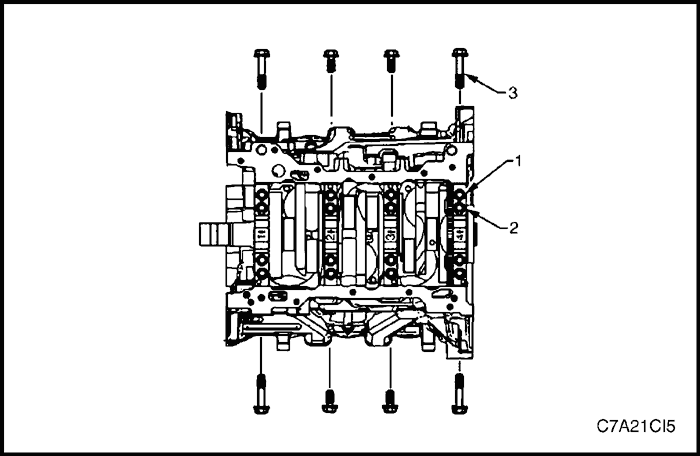
- Remove the crankshaft bearing cap side bolts (3).
Caution : The crankshaft bearing cap outer bolts are yield tightened during assembly and must be replaced prior to reassembly. Crankshaft bearing cap outer bolts that are not replaced will not torque to the correct clamp load and can lead to serious engine damage.
- Remove the crankshaft bearing cap outer bolts (1).
- Remove the crankshaft bearing cap inner bolts (2).
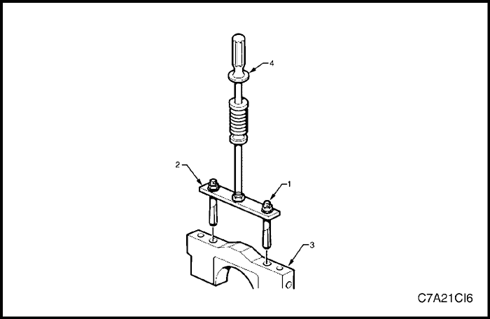


- Loosen the nuts (1) of the crankshaft main bearing cap remover, Tool No. J-41818 (2) to separate the chamfered collets. Install the collets into the inner bolt holes of the front main bearing cap (3).
- Tighten the remover nuts to 11 N•m (97 lb-in).
- Install a slide hammer, Tool No. J-6125-1B (4) onto the crankshaft bearing cap remover and remove the crankshaft bearing cap.
- Repeat steps 9 to 13 for the remaining crankshaft bearing caps.
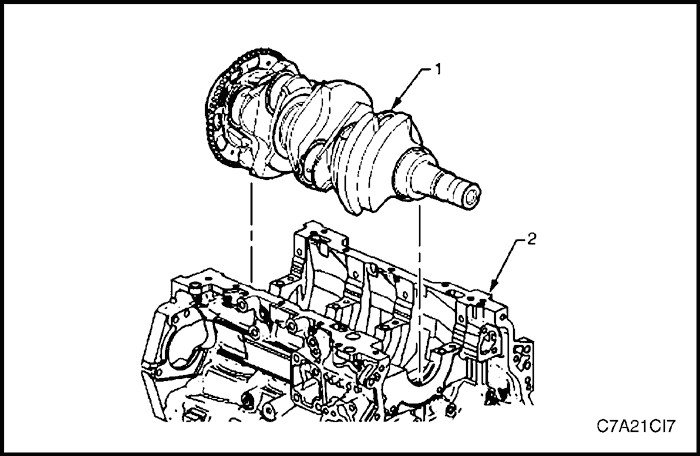


- Remove the crankshaft (1) from the engine block (2), lifting evenly to avoid jamming against the main thrust bearing.
- Place the crankshaft in a secure place.
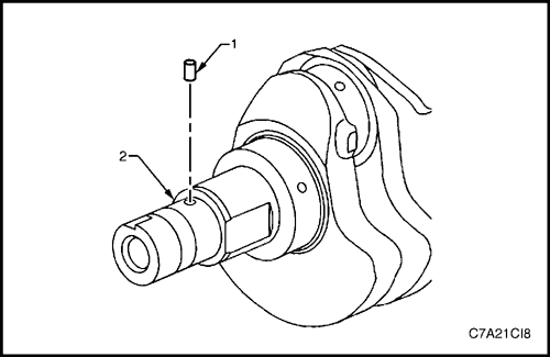


- If required, remove the crankshaft sprocket drive pin (1) from the crankshaft (2),
Crankshaft End Play Measurement
- Place a dial indicator at the end of the crankshaft nose.
- Gently force the crankshaft towards the front and rear of the cylinder block with a lever while monitoring the movement of the dial indicator.
- The crankshaft endplay should not exceed specifications.
- If the specifications are exceeded, inspect the thrust bearing thrust outer diameter and the crankshaft thrust wall for wear and/or excessive runout. Compare the values with the specifications.
- Replace the thrust bearing or crankshaft as required.


Crankshaft Bearing
- Prepare a piece of cardboard or similar, numbered 1 - 4 for bearing identification.
Note : Main bearing journals are numbered from the front of the engine.
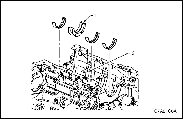
- Remove the crankshaft upper bearing halves from the cylinder block. Note the position of the thrust bearing (1) at the number 3 journal (2).
- Place the crankshaft upper bearing halves on the cardboard in the correct positions.
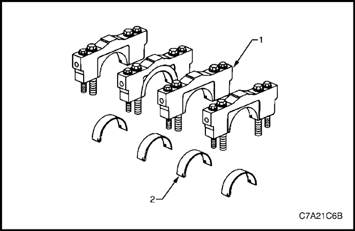


- Remove the crankshaft lower bearing halves (2) from the crankshaft bearing caps (1).
- Place the crankshaft lower bearing halves in the correct positions on the cardboard.
Clean and Inspection
Crankshaft and Main Bearing Cleaning
- Clean the following components in solvent and then dry with compressed air:
- crankshaft bearings,
- connecting rod bearings,
- crankshaft journals,
- crankpin journals,
- crankshaft oil passages, and
- crankshaft threaded holes.
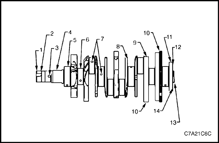


Crankshaft and Main Bearing Visual Inspection
- Perform the following visual inspections:
- Inspect the crankshaft balancer bolt hole (1) for thread damage.
- Inspect the crankshaft balancer mounting area (2) for damage.
- Inspect the crankshaft sprocket pin hole (3) for damage.
- Inspect the oil pump drive flats (4) for damage.
- Inspect the crankshaft main journals (5) for damage.
- Inspect the crankshaft connecting rod journals (6) for damage.
- Inspect the crankshaft oil passages (7) for obstructions.
- Inspect the crankshaft main bearing thrust wall surfaces (8) for damage.
- Inspect the crankshaft counterweights (9) for damage.
- Inspect the crankshaft reluctor ring teeth (10) for damage.
- Inspect the crankshaft rear main oil seal surface (11) for damage.
- Inspect the crankshaft engine flexplate mounting surface (12) for damage.
- Inspect the crankshaft pilot hole (13) for damage.
- Inspect the crankshaft engine flywheel bolt holes (14) for thread damage.
- Repair or replace the crankshaft as required.


Crankshaft Main Bearing Inspection
Caution : All connecting rod and main journal bearings that have been used in a running engine must be replaced. Never re-use the crankshaft or connecting rod bearings.
Note : The following bearing wear conditions should be used to diagnose engine operating conditions or root cause of a condition.
- Inspect for fatigue indicated by craters or pockets (2). Flattened sections on the bearing halves (1) also indicate fatigue.
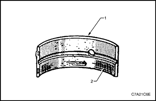


- Inspect for excessive scoring or discoloration (2) on both front and back of the bearing halves (1).
- Inspect the main bearings for dirt embedded into the bearing material.
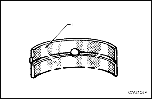


- Inspect for incorrect seating indicated by bright, polished sections (1).
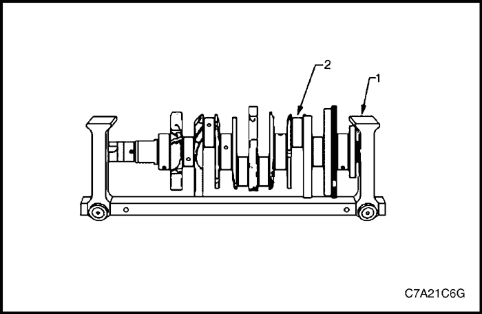


Crankshaft Measurement
- Using a suitable fixture (1), support the crankshaft (2).
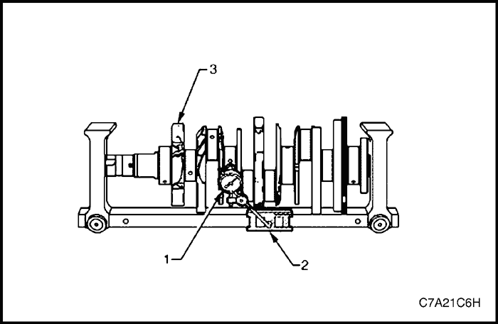


- Using a dial indicator (1) and magnetic base (2), rotate the crankshaft (3) carefully by hand. Measure the crankshaft main journals for runout and compare with the engine specifications.
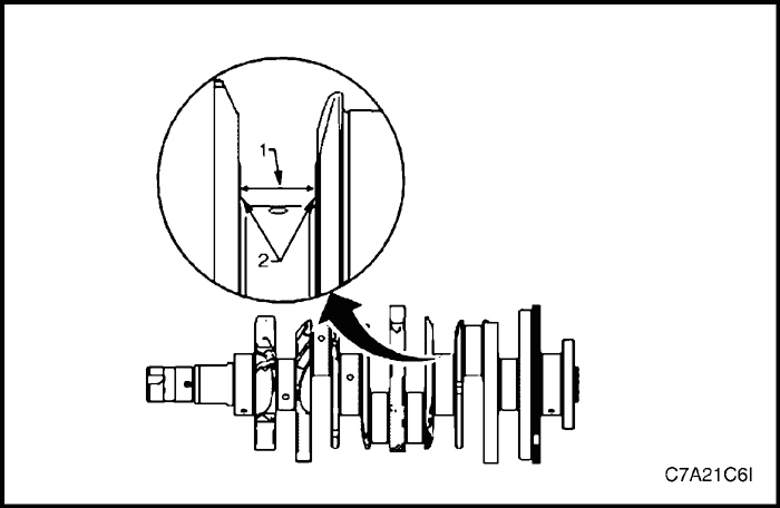


- Measure the crankshaft thrust wall width (1) for wear using an inside micrometer and compare with the engine specifications.
- Measure the crankshaft thrust wall surface (2) for runout using a dial indicator, mounted to a magnetic stand and compare with the engine specifications.
- If the crankshaft journals are damaged or worn beyond specifications, the crankshaft may be ground 0.25 mm. There is only one size of oversized main bearings available for service.
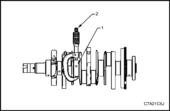


- Inspect the crankshaft main journals (1) for undersize, using an outside micrometer (2).
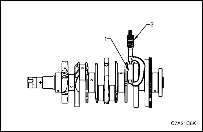


- Inspect the crankpins (1) for undersize using an outside micrometer (2).
- Compare your measurements with those listed in the engine specifications. If the crankpin journals are worn beyond the specifications, the crankshaft may be ground 0.25 mm. Only one size of oversized connecting rod bearings available for service.
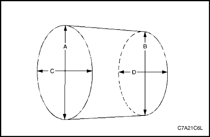


- Measure the main bearing and crankpin journals for out-of-round using the following procedure:
- a. Using an outside micrometer, measure the journal at the extreme front and rear locations on the journal. Call these points A and B.
- b. Measure the journal in two new locations exactly 90 degrees from the first points. Call these points C and D.
- c. Subtract A from C and B from D. The differences will indicate journal out-of-round.
- d. The out-of-round should not exceed 0.004 mm maximum.
- e. If the journals are worn beyond the specifications, the crankshaft may be ground 0.25 mm. There is only one size of oversized crankshaft and connecting rod bearings available for service.
- If the journals are worn beyond the specifications, the crankshaft may be ground 0.25 mm. There is only one size of oversized crankshaft and connecting rod bearings available for service.
- a. Using an outside micrometer, measure the journal at the extreme front (A) and rear (B) of the journal parallel to the crankshaft centreline.
- b. Subtract the smallest from the largest measurement. The result will be the journal taper.
- c. If the main bearing journal taper exceeds 0.004 mm, replace the crankshaft.
- d. If the journals are worn beyond the specifications, the crankshaft may be ground 0.25 mm. There is only one size of oversized crankshaft and connecting rod bearings available for service.


Installation Procedure
Crankshaft Bearing Installation Procedure
Caution : If the crankshaft bearings have been used in a running engine, replace them with new crankshaft bearings for reassembly.
- Clean the crankcase crank bore with a lint-free cloth.
- Clean all the oil from the backside of new bearing halves.
- Install the new upper crankshaft bearings into position. The thrust bearing (1) belongs in the number 3 journal(2). Ensure the upper bearing insert contains the oil transfer hole and groove. Roll the bearing into position so the lock tang engages the crank slot. The bearing must fit flush with the upper crankcase.


- Install the new lower crankshaft bearings (2) into position in the main bearing caps (1). The lower crankshaft bearings are identified by no grooves or holes. The bearings must fit flush with the crankshaft bearing caps.
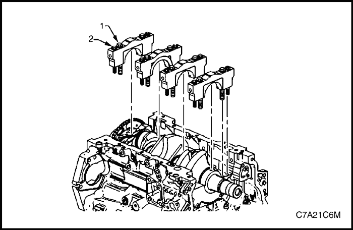


Crankshaft Main Bearing Clearance Measurement
- Place a length of fresh, room temperature plastic gauging material all the way across all the crankshaft bearing journals.
- Install the crankshaft main bearing caps.
- Loosely install the original inner main cap bolts (1).
- Loosely install the original outer main cap bolts (2).


- Loosely install the original short/inner side main cap bolts.
- Loosely install the original long/outer side main cap bolts (3).
- Gently tap the crankshaft main bearing caps with a soft-faced hammer to help seat the caps.
- Tighten the main caps bolts.
Tighten
- Tighten the crankshaft main bearing cap inboard attaching bolt to 20 N•m (15 lb-ft) plus another 80°.
- Tighten the crankshaft main bearing cap outboard attaching bolt to 15 N•m (11 lb-ft) plus another 110°.
- Tighten the crankshaft main bearing cap side attaching bolt to 30 N•m (22 lb-ft) plus another 60°.
Note : Do not rotate the crankshaft.
- Allow the assembly to sit for 2 minutes.


- Remove the crankshaft bearing cap side bolts.
- Remove the crankshaft bearing cap outer bolts (2).
- Remove the crankshaft bearing cap inner bolts (1).
- Install the crankshaft main bearing cap remover Tool No. J-41818 as previously described and remove the crankshaft bearing cap.
- Repeat steps 10 to 13 for the remaining crankshaft bearing caps.
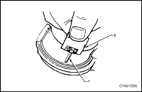


- Determine the crankshaft bearing clearance by comparing the width of the flattened plastic gauging material (1) at its widest point with the graduation on the gauging material scale (2).
- Compare the measurements listed in the specifications. If the new bearings do not provide the correct crankshaft to bearing clearance, inspect the following:
- a. Measure the crankshaft journals for the correct specified size and ensure new bearings are being installed. If the crankshaft journals are incorrectly sized, replace or regrind the crankshaft. Crankshaft machining is permitted and undersized bearings are available.
- b. Measure the engine block crankshaft bearing bore diameter to ensure correct size. The engine block crankshaft bearing bore is not machineable and the block must be replaced if out of specification.
- Clean the plastic gauging material from the crankshaft bearing journals with a soft, lint-free cloth.


Crankshaft Final Installation Procedure
- If removed, install the crankshaft sprocket drive pin (1). Lightly tap the pin in place with a small soft face, bronze/plastic, hammer until it bottoms in the hole.
Caution : Ensure the crankshaft position sensor has been removed from the cylinder block prior to loading the crankshaft, as damage to the sensor may occur.
- Apply a liberal amount of clean engine oil to the upper and lower bearing surfaces.
- Gently lower the crankshaft (1) into position in the cylinder block (2).


- Install the crankshaft main bearing caps.
- Loosely install the original inner main cap bolts (1).
Caution : The outer crankshaft bearing cap bolts (2) are yield tightened during assembly and must be replaced prior to reassembly. Outer crankshaft bearing cap bolts that are not replaced will not torque to the correct clamp load and can lead to serious engine damage.
- Loosely install the new outer main bearing cap bolts (2).
- Gently tap the crankshaft main bearing caps with a soft-faced hammer to help seat the caps.


Caution : The short / inner side main cap bolts originally have a sealant on the flange of the bolt head. New bolts must be used. If new bolts are not used, oil can leak from the crankcase past the bolts.
- Loosely install new short / inner side main cap bolts (4).
Caution : The long / outer side main cap bolts originally have a sealant on the flange of the bolt head. New bolts must be used. If new bolts are not used, oil can leak from the crankcase past the bolts.
- Loosely install the new long / outer side main cap bolts (3).
- Tighten the main caps bolts.
Tighten
- Tighten the crankshaft main bearing cap inboard attaching bolt to 20 N•m (15 lb-ft) plus another 80°.
- Tighten the crankshaft main bearing cap outboard attaching bolt to 15 N•m (11 lb-ft) plus another 110°.
- Tighten the crankshaft main bearing cap side attaching bolt to 30 N•m (22 lb-ft) plus another 60°.
- Ensure the crankshaft turns without binding or noise.
- Install the remaining components in the reverse order to removal, refer to the appropriate Section.
 | |  | |
| © Copyright Chevrolet Europe. All rights reserved |


