To the top of the document
Captiva
To Previous Page To Next Page
GMDE Start Page Load static TOC Load dynamic TOC Help?

SECTION

SCHEMATIC AND ROUTING DIAGRAMS

ECM Wiring Diagram (2.4 DOHC - 1 OF 11)


C7A11F01
Display graphicTranslations of text in graphics


ECM Wiring Diagram (2.4 DOHC - 2 OF 11)


C7A11F02
Display graphicTranslations of text in graphics


ECM Wiring Diagram (2.4 DOHC - 3 OF 11)


C7A11F03
Display graphicTranslations of text in graphics


ECM Wiring Diagram (2.4 DOHC - 4 OF 11)


C7A11F04
Display graphicTranslations of text in graphics


ECM Wiring Diagram (2.4 DOHC - 5 OF 11)


C7A11F05
Display graphicTranslations of text in graphics


ECM Wiring Diagram (2.4 DOHC - 6 OF 11)


C7A11F06
Display graphicTranslations of text in graphics


ECM Wiring Diagram (2.4 DOHC - 7 OF 11)


C7A11F07
Display graphicTranslations of text in graphics


ECM Wiring Diagram (2.4 DOHC - 8 OF 11)


C7A11F08
Display graphicTranslations of text in graphics


ECM Wiring Diagram (2.4 DOHC - 9 OF 11)


C7A11F09
Display graphicTranslations of text in graphics


ECM Wiring Diagram (2.4 DOHC - 10 OF 11)


C7A11F10
Display graphicTranslations of text in graphics


ECM Wiring Diagram (2.4 DOHC - 11 OF 11)


C7A11F11
Display graphicTranslations of text in graphics


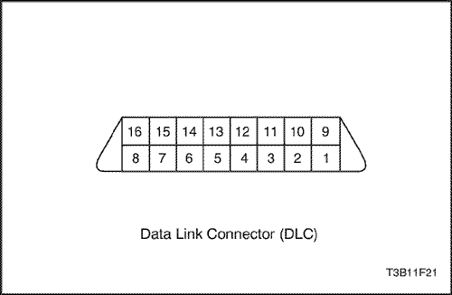
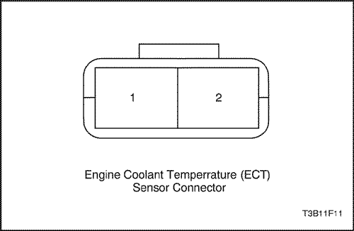
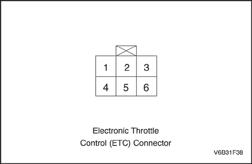
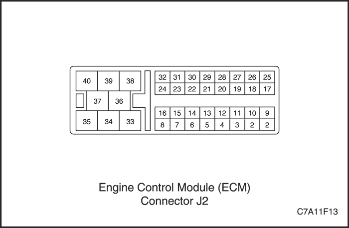
Connector END View


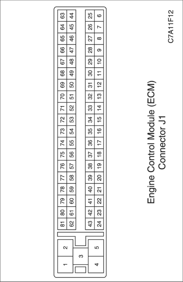
C7A11F12
Display graphicTranslations of text in graphics


T3B11F21
Display graphicTranslations of text in graphics


T3B11F11
Display graphicTranslations of text in graphics


V6B31F38
Display graphicTranslations of text in graphics


C7A11F13
Display graphicTranslations of text in graphics


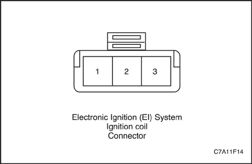
C7A11F14
Display graphicTranslations of text in graphics


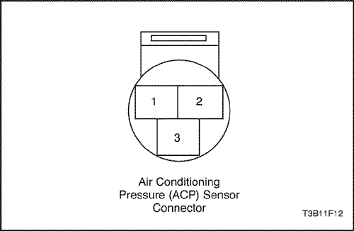
T3B11F12
Display graphicTranslations of text in graphics


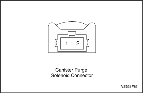
V3B31F83
Display graphicTranslations of text in graphics


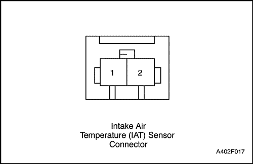
A402F017
Display graphicTranslations of text in graphics


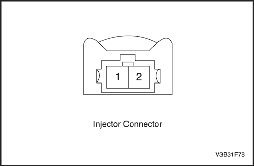
V3B31F78
Display graphicTranslations of text in graphics


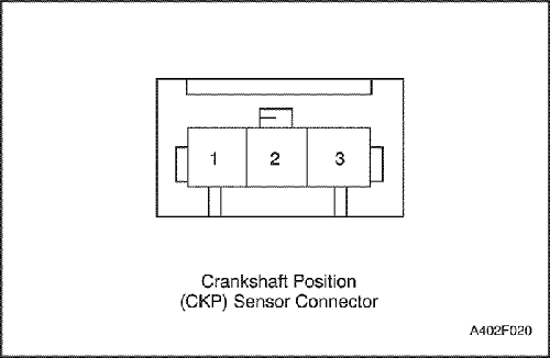
A402F020
Display graphicTranslations of text in graphics


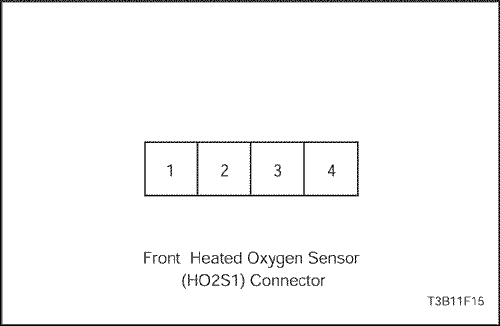
T3B11F15
Display graphicTranslations of text in graphics


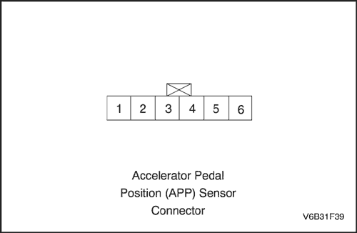
V6B31F39
Display graphicTranslations of text in graphics


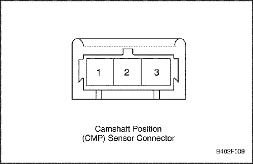
B402F009
Display graphicTranslations of text in graphics


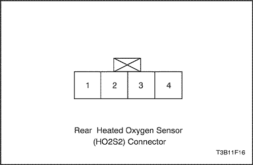
T3B11F16
Display graphicTranslations of text in graphics


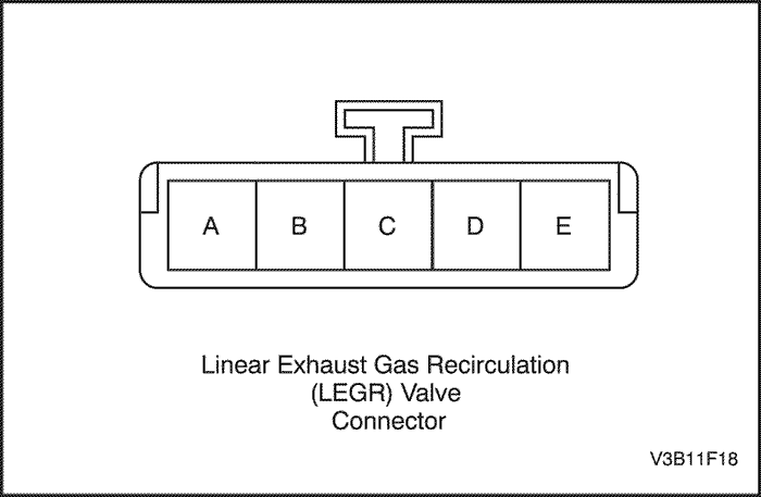
V3B11F18
Display graphicTranslations of text in graphics


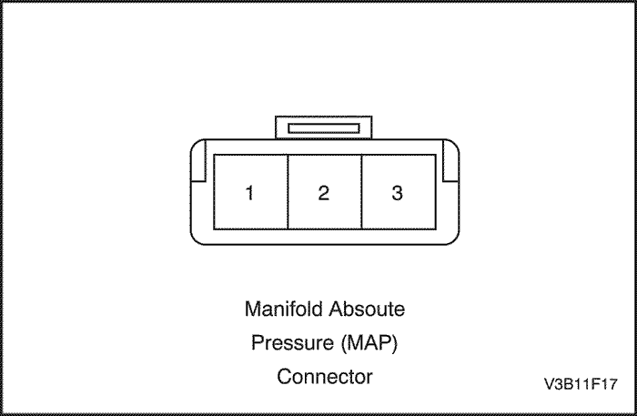
V3B11F17
Display graphicTranslations of text in graphics


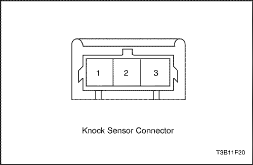
T3B11F20
Display graphicTranslations of text in graphics


COMPONENT LOCATOR

Component Locator
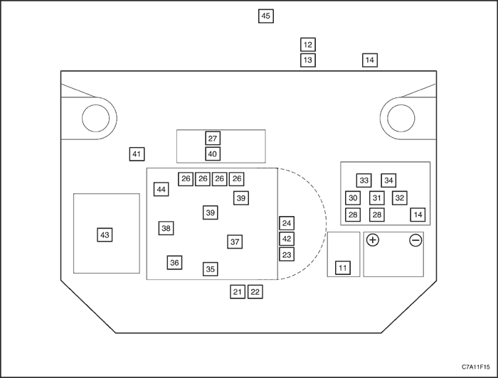

C7A11F15
Display graphicTranslations of text in graphics


Components on ECM Harness

  1. Engine Control Module (ECM)
  2. Data Link Connector (DLC)
  3. Malfunction Indicator Lamp (MIL)
  4. Fuse Panel (2)

ECM Controlled Device

  1. Main Cooling Fan Connector
  2. Aux Cooling Fan Connector
  3. Exhaust Gas Recirculation (EGR) Valve
  4. Direct Ignition System (DIS) Ignition Coil
  5. Evaporative Emission Control Purge Solenoid Valve
  6. Fuel Injectors (4)
  7. Electronic Controlled Throttle Body
  8. Starter Relay
  9. A/C Relay
  10. Main Relay
  11. Main Fan Relay
  12. Fan Control Relay
  13. Aux Fan Relay
  14. Fuel Pump Relay

Information Sensors

  1. Front Heated Oxygen Sensor
  2. Crankshaft Position (CKP) Sensor
  3. Rear Heated Oxygen Sensor
  4. Camshaft Position (CMP) Sensor
  5. Knock Sensor
  6. Manifold Absolute Pressure (MAP) Sensor
  7. Intake Air Temperature (IAT) Sensor
  8. Engine Coolant Temperature (ECT) Sensor

Not ECM Connected

  1. Air Cleaner Assembly
  2. Engine Oil Pressure Switch
  3. Evaporative Emission Canister Assembly (under vehicle, in front of the fuel tank)

To Previous Page To Next Page
© Copyright Chevrolet Europe. All rights reserved