UNIT REPAIR


Major Component Disassembly
Tools Required
DT-48179 Universal Driver Handle
DT-48182 Needle Sleeve Remover/Installer
DT-48183 Removal Bridge
DT-48189 Differential Bearing Race Remover
DT-48225 Input Shaft Holder
DT-48226 Transaxle Housing Groove Ball Bearing Remover/Installer
DT-48227 Roller Bearing Remover/Installer
DT-48228 Clutch Housing Groove Ball Bearing Remover/Installer
DT-48229 Interm Shaft Remover
DT-48231 Input and Outupt Shaft Pusher/Puller
DT-48232 Input Shaft Synchro Body Protector
Disassembly Procedure
- Remove the transaxle from the vehicle. Refer to "Transaxle Assembly" in this section.
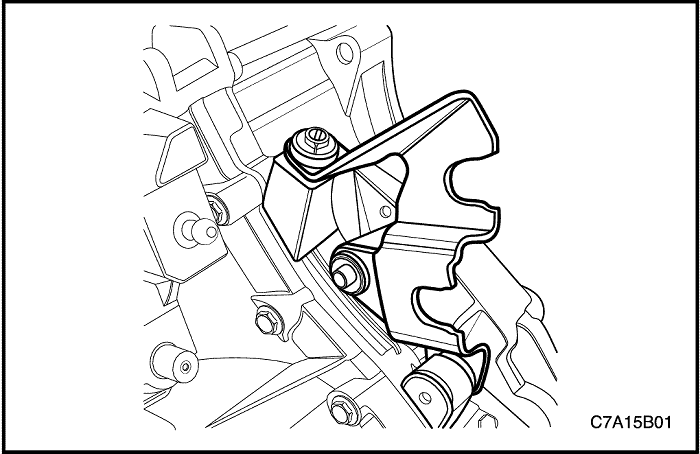
- Remove the bolts, the washer, and the shift control cable bracket.
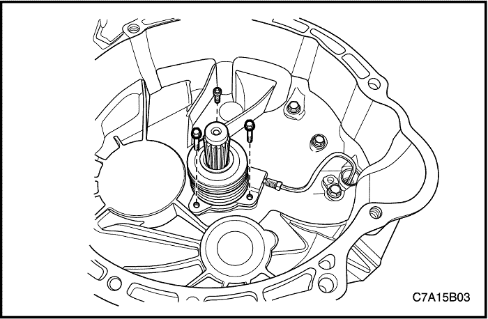


- Remove the concentric slave cylinder retaining bolts.
- Disconnect the concentric slave cylinder pipe from the concentric slave cylinder.
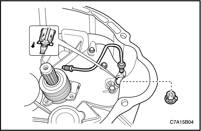


Important : When removing the bushing, Make sure not to remove it with excessive force.
- Remove the bushing from the concentric slave cylinder pipe.
- Remove the concentric slave cylinder pipe.
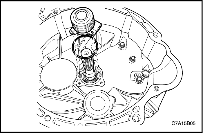


- Remove the O-ring and the concentric slave cylinder.
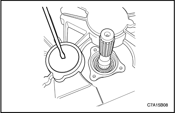


- Knock a hole in the sealing plug of the Interm shaft with a suitable tool.
Important : Puncture the sealing plug in the center to prevent damage to the transaxle.
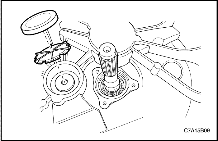


- Remove the Interm shaft sealing plug and the oil pipe using a suitable tool. Discard the sealing plug and the oil pipe.
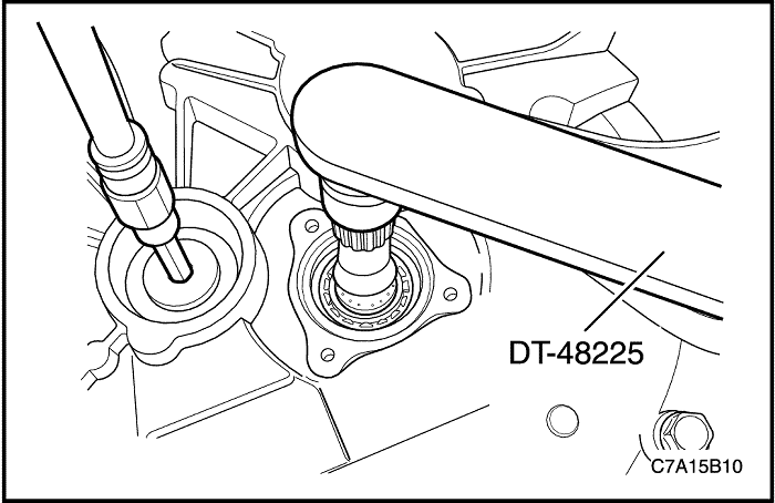


- Hold the input shaft with the DT-48225.
- Remove the retainer plug from the Interm shaft. Discard the retainer plug.
- Shift the transaxle into any gear.
- Remove the DT-48225.
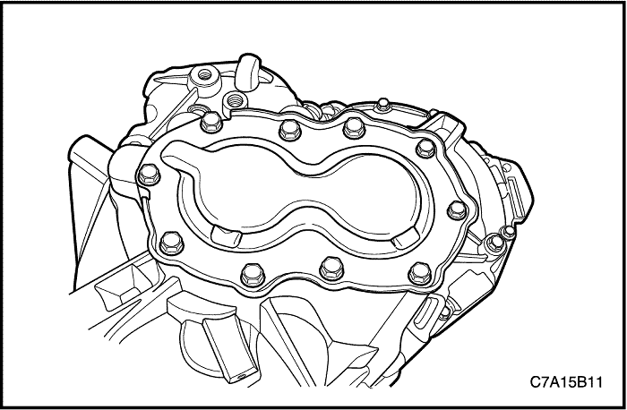


- Remove the transaxle rear cover bolts.
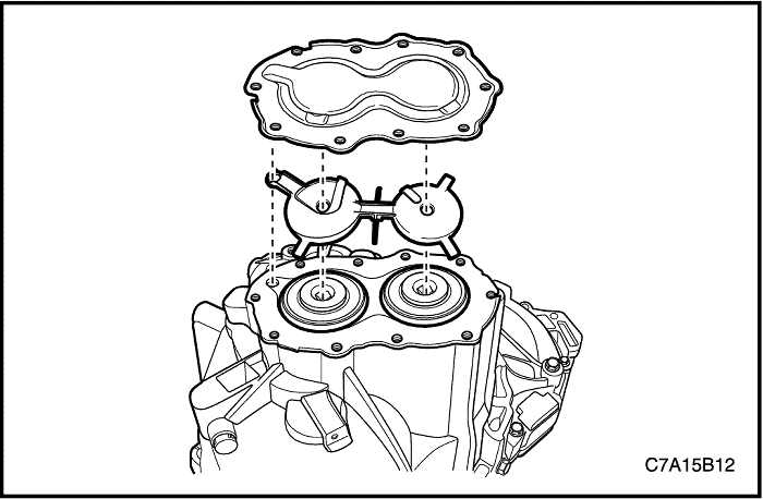


- Remove the transaxle rear cover and the oil pipe.
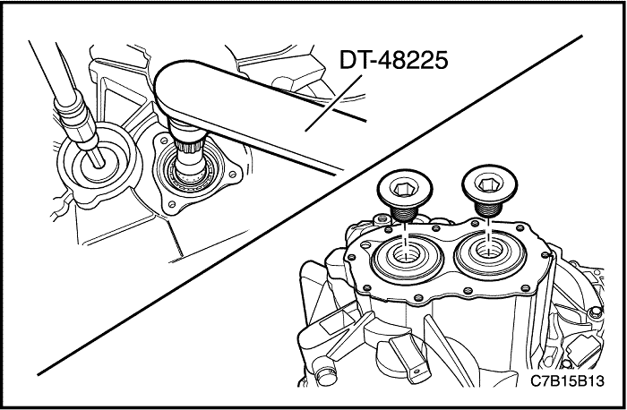


- Hold the input shaft with the DT-48225.
- Remove the input shaft retainer plug and the output shaft retainer plug. Discard the retainer plugs.
- Shift the transaxle into any gear.
- Remove the DT-48225.
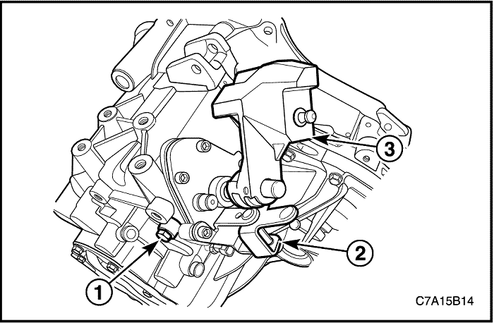


- Remove the shift shaft assembly.
- Position the transaxle into neutral.
- Remove the shift guide bolt (1).
- Remove the shift retaining bolts.
- Remove the select control lever (2).
- Remove the shift shaft assembly (3).
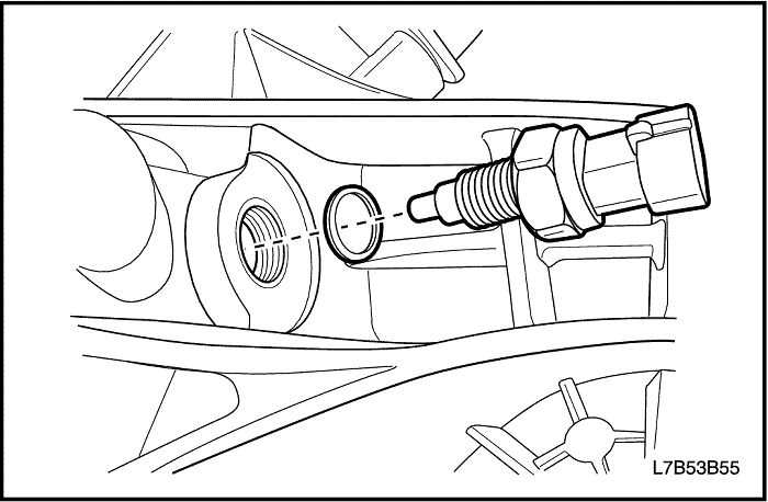


- Remove the backup lamp switch and the washer from the transaxle housing.
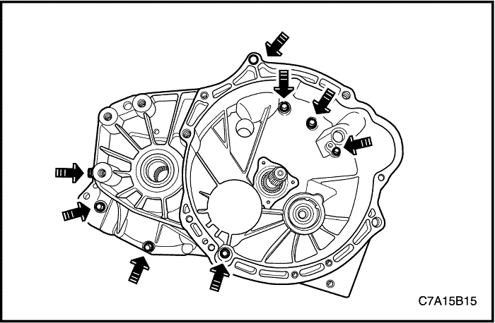


- Remove the eight bolts from the clutch housing side.
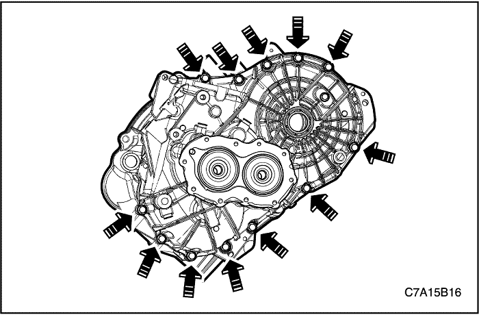


- Remove the twelve bolts from the transaxle housing side.


- Remove the transaxle housing from the clutch housing.
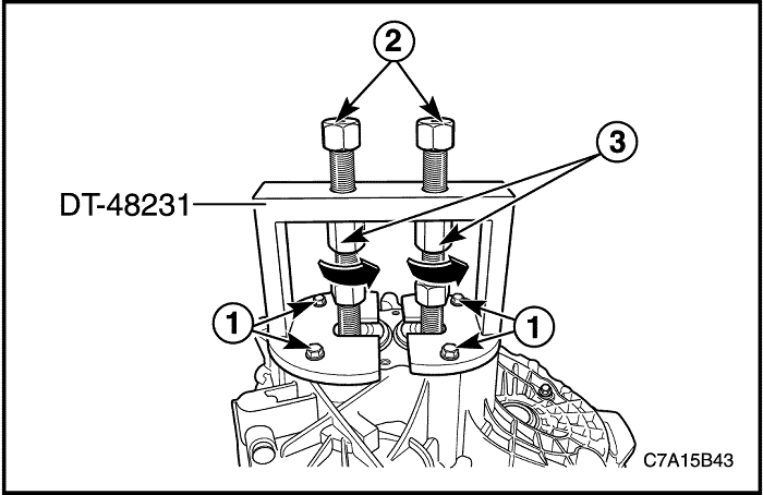
- Install the DT-48231 onto the transaxle housing.
- Tighten the four bolts (1).
- Screw the spindles (2) into the input and output shaft.
- Separate the transaxle housing from the clutch housing.
- Hold the spindles (2) using a suitable tool.
- Turn via nuts (3) in direction of arrow.
- Remove the DT-48231 from the transaxle housing.
- Unscrew the spindles (2) into the input and output shaft.
- Remove the four bolts (1).
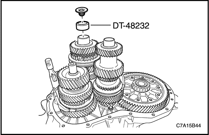


- Install the DT-48232 and the retainer plug to the input shaft.
Important : This prevents the 3rd/4th synchro body assembly falling apart.
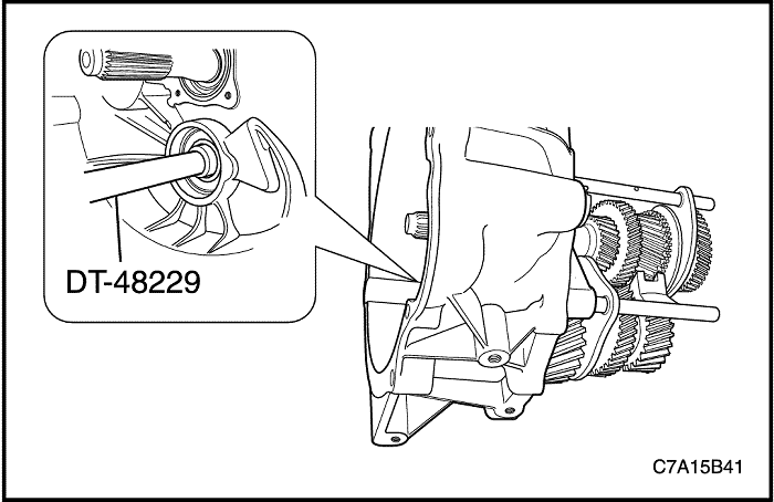


- Remove Interm, input and output shaft assembly with the respective shift forks out of the clutch housing.
- Knock interm shaft out of interm shaft groove ball bearing using the DT-48229.
Important : Hold the input and output shaft assembly firmly.
- Remove the DT-48232 and the retainer plug from the input shaft.
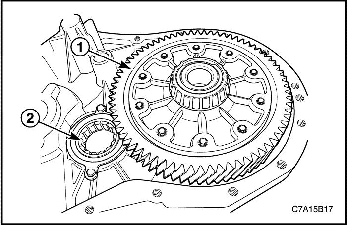


- Remove the differential (1) and the output shaft roller bearing (2) From the clutch housing.
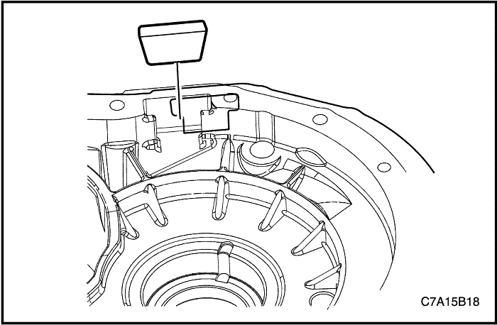


- Remove the magnet from the transaxle housing.
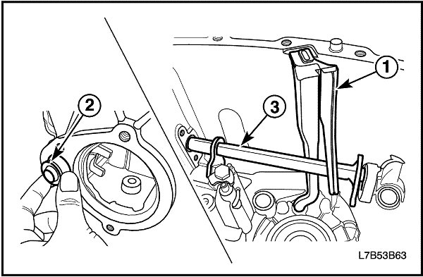


- Remove the drain channel (1) from the transaxle housing.
- Remove the idle shift rail bushing (2) from the transaxle housing.
- Remove the idle shift rail (3) from the transaxle housing.
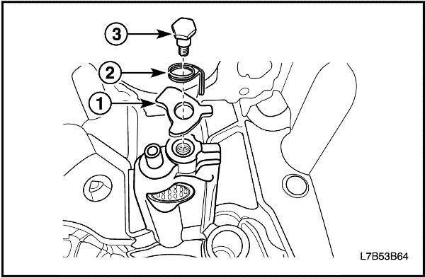


- Remove the thread pin (3), the torsion spring (2), and the reverse shifting blocker (1) from the transaxle housing. Discard the thread pin.
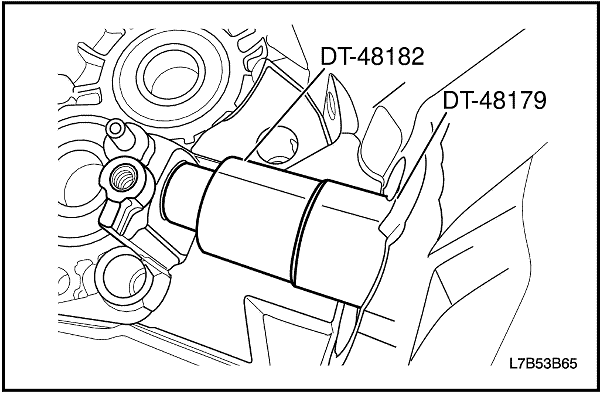


- Remove the needle sleeve from the transaxle housing using the DT-48179 and the DT-48182.
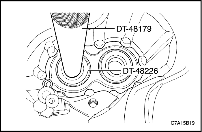


- Remove the input shaft and output shaft groove ball bearings from the transaxle housing using the DT-48179 and the DT-48226.
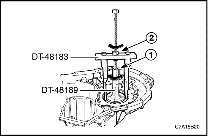


- Remove the differential bearing race from the transaxle housing.
- Install the DT-48189.
- Turn the nut (1) in direction of arrow.
- Install the DT-48183 to the DT-48189.
- Hold the spindle using a suitable tool.
- Turn the nut (2) in direction of arrow.
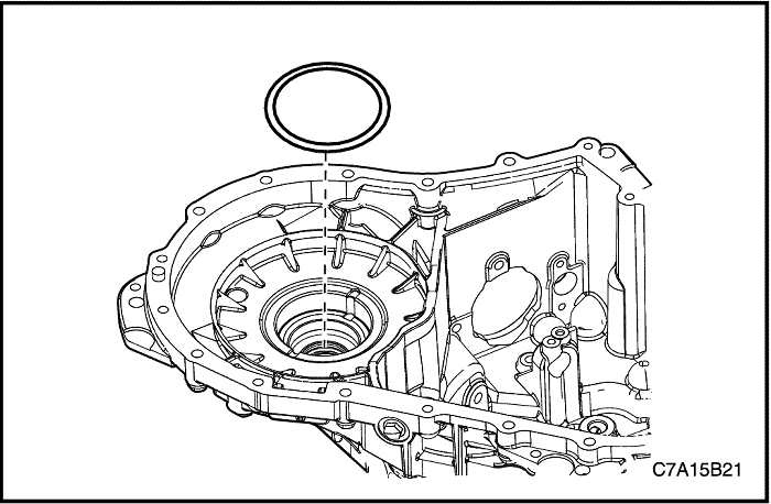


- Remove the shim from the transaxle housing.
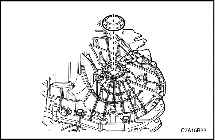


- Remove the shaft seal ring from the transaxle housing. Discard the shaft seal ring.
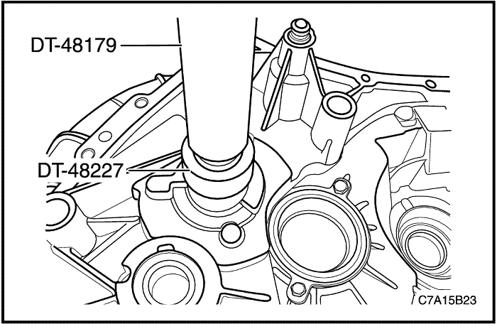


- Romove the input shaft roller bearing from the clutch housing using the DT-48179 and the DT-48227.
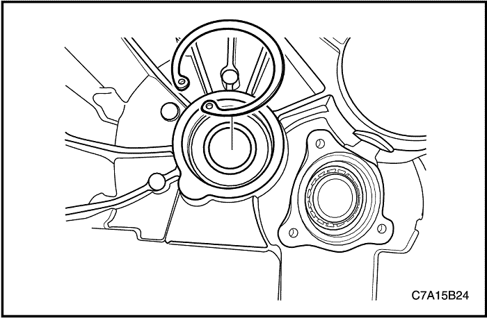


- Remove the snap ring from the Interm shaft groove ball bearing.
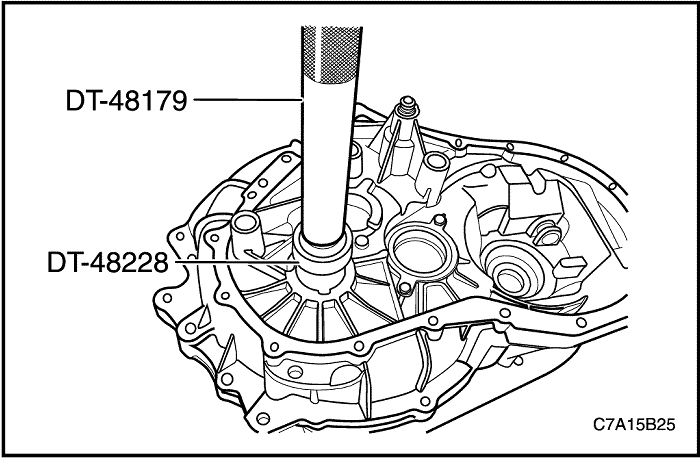


- Remove the Interm shaft groove ball bearing from the clutch housing using the DT-48179 and the DT-48228.
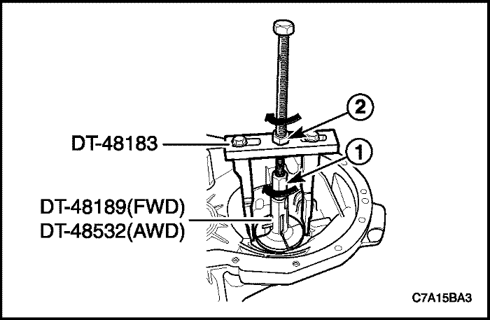


- Remove the differential bearing race from the clutch housing.
- For FWD, Install the DT-48189 and For AWD, Install the DT-48532.
- Turn the nut (1) in direction of arrow.
- Install the DT-48183 to the DT-48189 (For FWD) or the DT-48532 (For AWD).
- Hold the spindle using a suitable tool.
- Turn the nut (2) in direction of arrow.
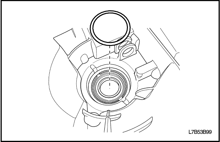


- Remove the shim from the clutch housing.
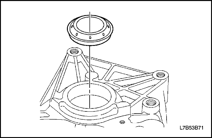


- Remove the shaft seal ring from the clutch housing. Discard the shaft seal ring.
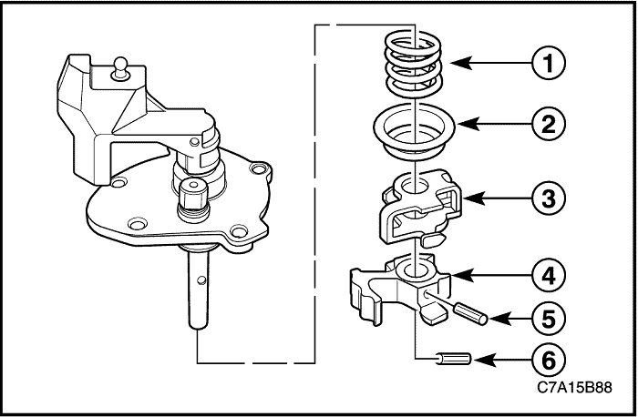


Shift Shaft Disassembly
Disassembly Procedure
Important : Observe the orientation of the coiled pin before removal.
- Remove the coiled pin (6). Discard the coiled pin.
- Remove the coiled pin (5). Discard the coiled pin.
- Remove the shift interlock (3).
- Remove the shift finger (4).
- Remove the outer spring seat (2).
- Remove the 5th/reverse pressure spring (1).
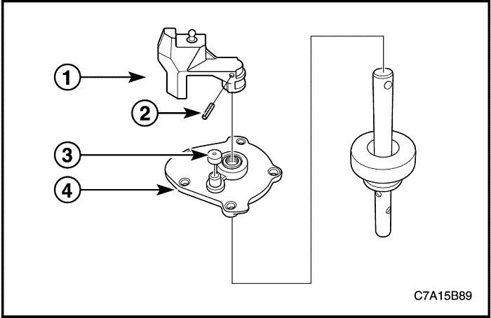


- Remove the coiled pin (2). Discard the coiled pin.
- Remove the shift lever (1).
- Remove the vent cap (3).
- Remove the shift cover (4).
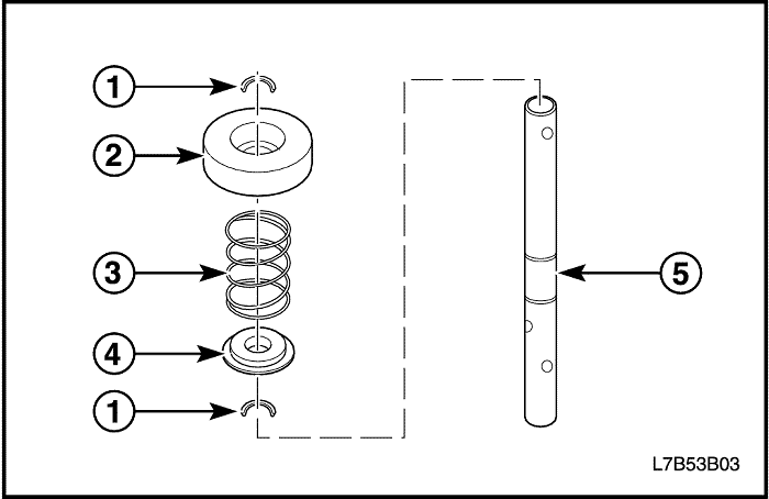


- Remove the snap rings (1). Discard the snap rings.
- Remove the inner spring seat (2).
- Remove the 1st/2nd pressure spring (3).
- Remove the angle disc (4) from the shift rod (5).
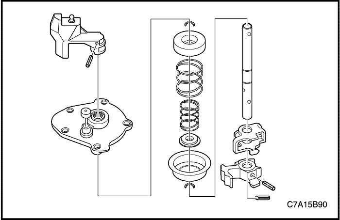


- Clean all components in a suitable solution.
- Inspect all components for wear or damage.


Interm Shaft Disassembly
Tools Required
DT-48233 Interm Shaft Press Adapter
Disassembly Procedure
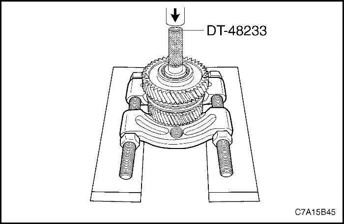
- Press off the 1st gear assembly and the 2nd gear assembly as a unit, from the Interm shaft using the gear and bearing separator plate, the DT-48233, and a hydraulic press.
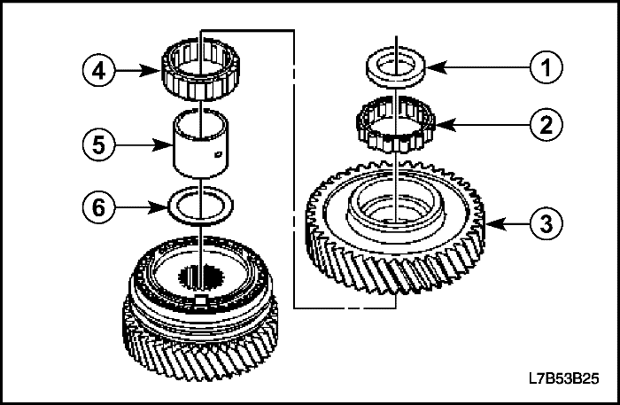


- Put the 1st gear assembly and the 2nd gear assembly, as a unit, on the bench.
- Remove the thrust washer (1).
- Remove the roller bearing (2).
- Remove the 1st gear (3).
- Remove the roller bearing (4).
- Remove the bearing collar (5).
- Remove the thrust washer (6).
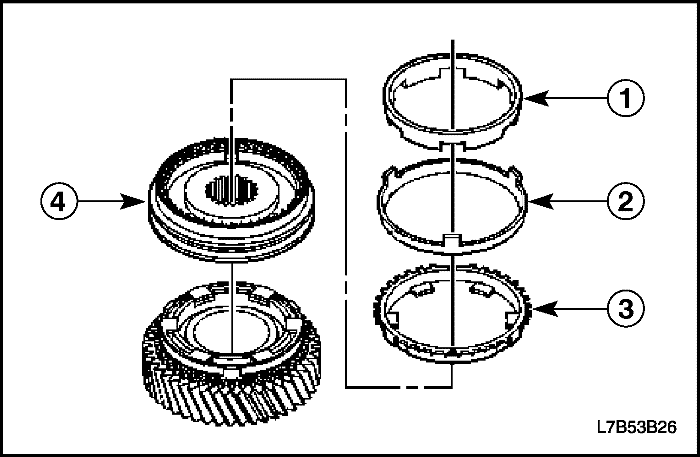


- Remove the 1st gear inner cone (1).
- Remove the 1st gear blocking ring (2).
- Remove the 1st gear outer cone (3).
- Remove the 1st/2nd synchronizer assembly (4).
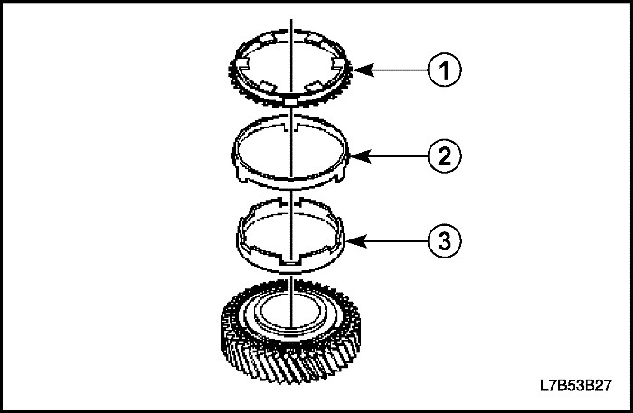


- Remove the 2nd gear outer cone (1).
- Remove the 2nd gear blocking ring (2).
- Remove the 2nd gear inner cone (3).
- Remove the 2nd gear.
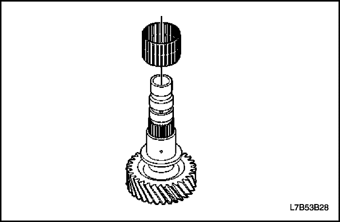


- Remove the needle bearings from the interm shaft.


Input Shaft Disassembly
Tools Required
DT-48234 Input/Output Shaft Press Adapter
Disassembly Procedure
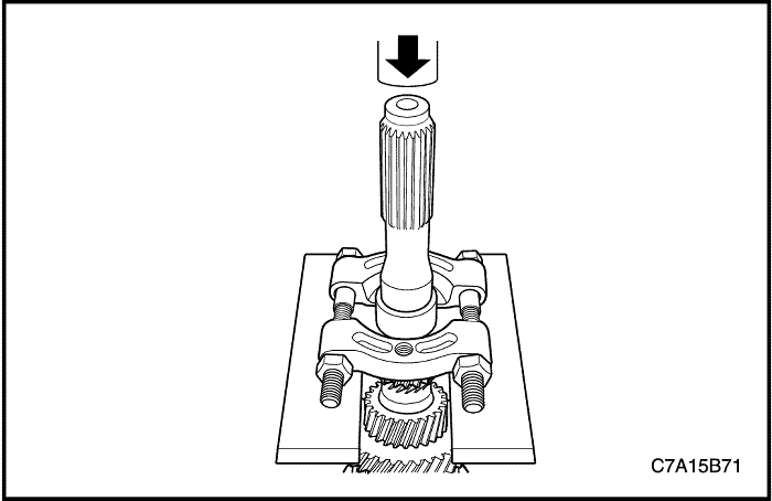
- Remove the sleeve bearing using the gear and bearing separator plate, and hydraulic press.
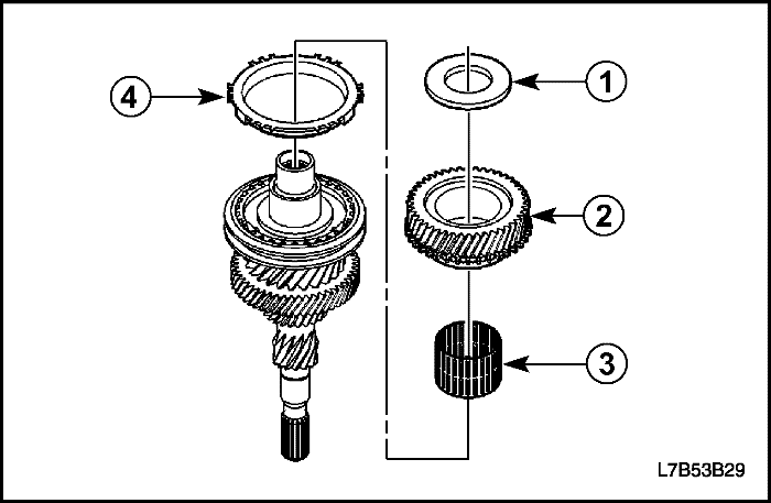


- Remove the thrust washer (1).
- Remove the 4th gear (2).
- Remove the needle bearing (3).
- Remove the 4th gear blocking ring (4).
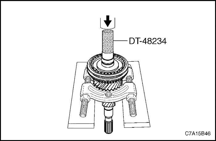


- Remove the bearing collar and the 3rd/4th synchronizer from the input shaft using the gear and bearing separator plate under the 3rd speed gear, the DT-48234, and a hydraulic press.
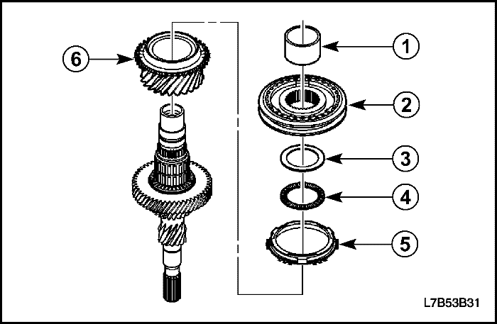


- Remove the following components as an assembly:
- The bearing collar (1).
- The 3rd/4th synchronizer assembly (2).
- The thrust washer (3).
- The thrust bearing (4).
- The 3rd gear blocking ring (5).
- The 3rd gear (6).
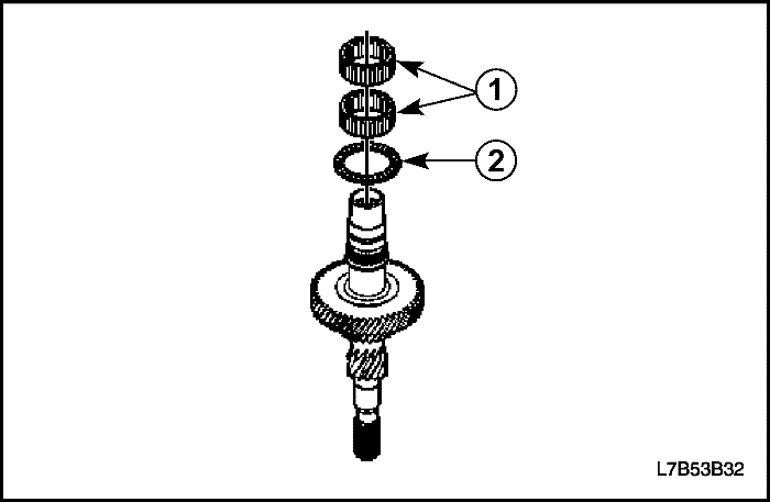


- Remove the needle bearing (1).
- Remove the thrust bearing (2).
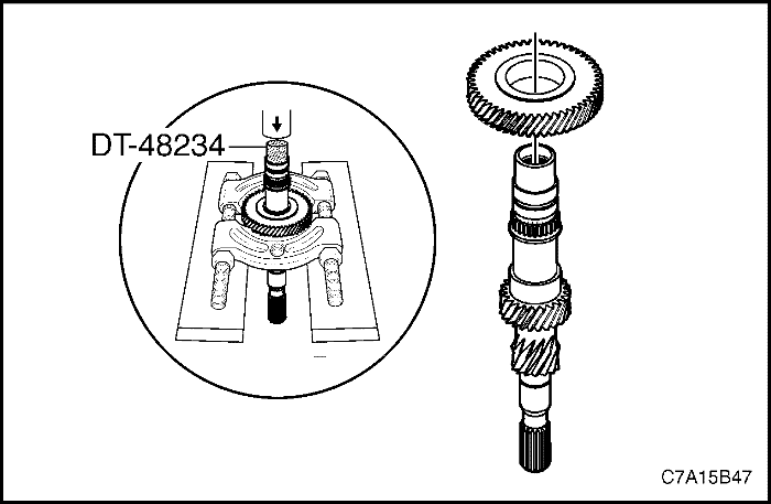


- Press off 5th gear using the gear and bearing separator plate, the DT-48234, and a hydraulic press.
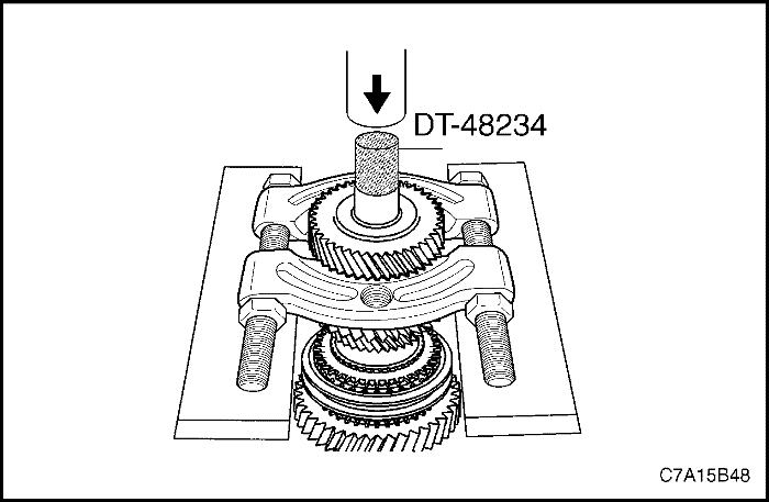


Output Shaft Disassembly
Tools Required
DT-48234 Input/Output Shaft Press Adapter
Disassembly Procedure
- Press off the 4th driven gear using the gear and bearing separator plate, the DT-48234, and a hydraulic press.
Important : The 4th driven gear is a very tight press.
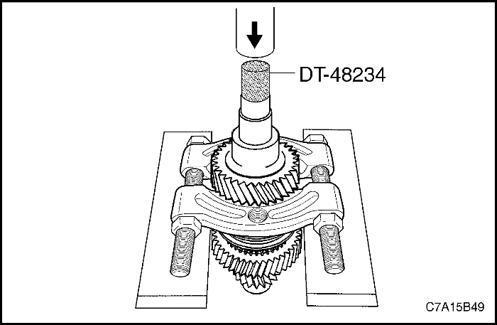


- Remove the 3rd driven gear using the gear and bearing separator plate, the DT-48234, and a hydraulic press.
Important : The 3rd driven gear is a very tight press.
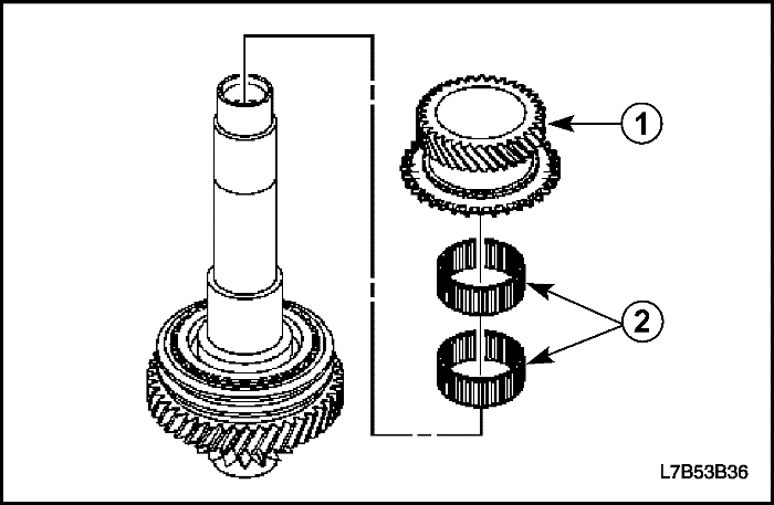


- Remove the 5th gear(1) and the two needle bearings (2).
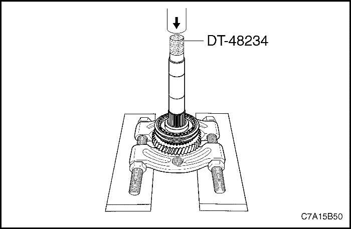


- Remove the bearing collar using the gear and bearing separator plate, the DT-48234, and a hydraulic press.
Important : Do not contact the thrust washer under the reverse gear.
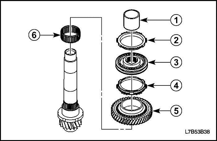


- Remove the following components as an assembly :
- The bearing collar (1).
- The 5th gear blocking ring (2).
- The 5th/Reverse synchronizer assembly (3).
- The reverse blocking ring (4).
- The reverse gear (5).
- The needle bearing (6).
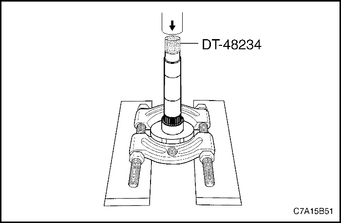


- Remove the collar and the thrust washer using the gear and bearing separator plate, the DT-48234, and a hydraulic press.
Important : Ensure that the gear and bearing separator plate is not making contact with the pinion gear before pressing off the collar and thrust washer.


Clutch and Transaxle Housing Cleaning and Inspection
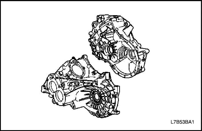
Inspect the clutch housing and the differential housing for the following :
- Cracks
- Porosity
- Damaged mating surface
- Stripped bolt threads
- Distortion
Replace any part that exhibits any of these conditions.


Gears Cleaning and Inspection
Inspect the gear teeth and the gear splines for excessive wear or damage.
Remove minor nicks or scratches with an oil stone. Replace worn or damaged gears.


Thrust Washer and Bearing Cleaning and Inspection
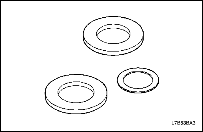
- Inspect the thrust washer for wear or damage. Replace worn or damaged thrust washers.
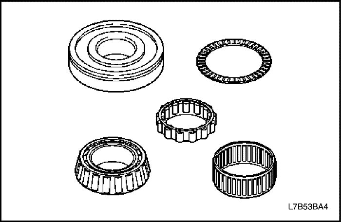


- Inspect the condition of all thrust bearings, input shaft bearing, and output shaft bearing. Wash the bearings thoroughly in a cleaning solvent. Apply compressed air to the bearings. Lubricate the bearings with light oil. Check the bearings for roughness by slowly turning the race by hand.
Important : Do not allow the bearings to spin. Turn the bearings slowly by hand. Spinning bearings may cause damage to the rollers.
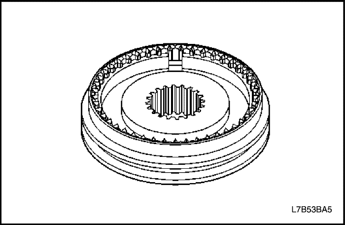


Synchronizers Cleaning and Inspection
- Clean the synchronizer with clean solvent.
- Air dry the components.
- Inspect the synchronizer teeth for the following conditions :
- Wear
- Scuffing
- Nicks
- Burrs
- Breaking
- Inspect the keys or the springs for the following :
- Wear
- Cracks
- Distortion
- If any of the following conditions exist, replace synchronizer.
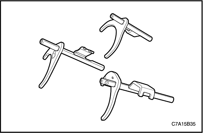


Shift Fork Cleaning and Inspection
Inspect the shift forks for wear or damage. Replace any part that is worn or damaged.
| © Copyright Chevrolet Europe. All rights reserved |


