MAINTENANCE AND REPAIR
ON-VEHICLE SERVICE


Transaxle Fluid Checking Procedure
Important : It is not necessary to check the fluid level unless the fluid has been changed or a leak is suspected. Inspect the fluid level only when the engine is off. Ensure the vehicle is level.
- Raise and support the vehicle.
- Remove the fluid level check plug.
- Verify that the fluid is level with the opening.
- If the transaxle is not properly filled, carefully add SAE75W90 fluid until it begins to flow out of the fill/check plug.
- Install a new fluid level check plug.
Tighten
Tighten the fluid level check plug to 6 N•m (53 lb-in) + 45°~180°.
- Lower the vehicle.
Transaxle Fluid Replacement
Caution : The transaxle fluid is hot. Caution must be taken to prevent personal injury when the transaxle fluid drains from the transaxle.
- Raise and support the vehicle.
- Remove the transaxle drain plug and allow the transaxle to drain completely.
- Remove the fluid level check plug.
- Install a new transaxle drain plug.
Tighten
Tighten the transaxle drain plug to 6 N•m (53 lb-in) + 45°~180°.
- Add SAE75W90 transaxle fluid until it seeps out of the fluid level check plug.
- Install a new fluid level check plug.
Tighten
Tighten the fluid level check plug to 6 N•m (53 lb-in) + 45°~180°.
- Lower the vehicle and verify proper operation.
|
Fluid Specification
|
SAE75W90
|
|
Fluid Capacity
|
FWD
|
2.1L (2.22 qt)
|
|
AWD
|
2.3L (2.43 qt)
|
Shift Control Lever Housing
Removal Procedure
- Disconnect the negative battery cable.
- Remove the console. Refer to Section 9G, Interior Trim.
- Disconnect the shift control cables from the shift control lever housing. Refer to "Shift Control Cable"
in this section.
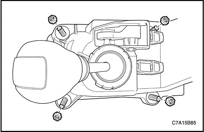
- Remove the nuts from the shift control lever housing.
- Remove the shift control lever housing.
Installation Procedure
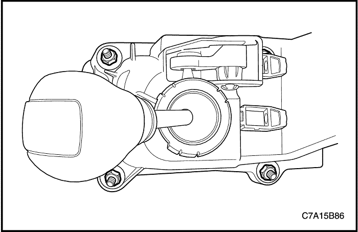
- Install the shift control lever housing.
- Install the nuts to the shift control lever housing.
Tighten
Tighten the shift control lever housing bolts to 8 N•m (71 lb-in).
- Connect the shift cables to the shift control lever housing, and adjust the cable. Refer to "Shift Control Cable"
in this section.
- Install the console. Refer to Section 9G, Interior Trim.
- Connect the negative battery cable.
Shift Control Cable
Removal Procedure
- Disconnect the negative battery cable.
- Remove the console. Refer to Section 9G, Interior Trim.
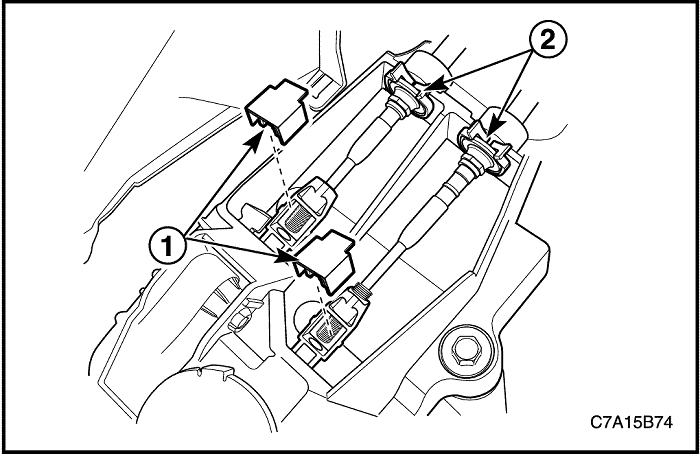
- Remove the shift control cable adjust locks (1).
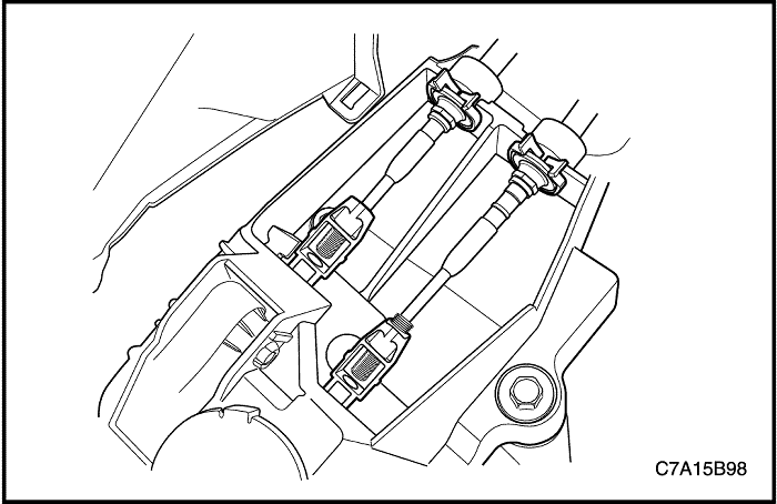
- Remove the shift control cables (2) from the shift control lever housing bracket.
- Disconnect the shift control cables from the shift control adjusters.

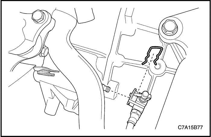
- Remove the shift control cables (1) from the transaxle using a suitable tool.
- Remove the cables (2) from the shift control cable bracket.
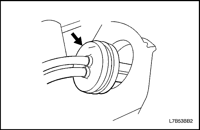
- Remove the grommet from the dash pannel.
- Remove the shift control cables from the vehicle.
Installation Procedure
- Install the shift control cables to the vehicle.
- Install the grommet from the dash pannel.
Important : Ensure that the shift control cable pass-through grommet is properly seated and the grommet arrow is pointing up.
- Install the cables (2) to the shift control cable bracket.
- Install the shift control cables (1) to the transaxle.
- Position the transaxle into NEUTRAL.
- Connect the shift control cables into the shift control adjusters.
- Install the shift control cables to the shift control lever housing bracket.

- Position the shift lever into NEUTRAL.
- With the shift cable ends in the adjusters, adjust the cables by pushing the neutral lock pin. Move the shifter slightly to center the neutral lock pin.
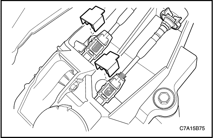
- Press and lock the shift control cable adjust locks.
- Pull the neutral lock pin to the original position.
- Install the console. Refer to Section 9G, Interior Trim.
- Connect the negative battery cable.
Shift Control Cable Adjustment
- Disconnect the negative battery cable.
- Position the transaxle into NEUTRAL.
- Connect the shift control cables into the shift control adjusters.
- Install the shift control cables to the shift control lever housing bracket.
- Position the shift lever into NEUTRAL.
- Adjust the cable by pushing the neutral lock pin. Move the shifter slightly in order to center the neutral lock pin.
- Press and lock the shift control cable adjust locks.
- Pull the neutral lock pin to the original position.
- Connect the negative battery cable.
Transaxle Assembly
Tools Required
DW110-060 Engine Assembly Support Fixture
Removal Procedure
- Remove the battery and the battery tray. Refer to Section 1E1, Engine Electrical - 2.0 Diesel ;
Section 1E2, Engine Electrical - FAM II 2.4D.
- Remove the power steering oil reservoir mounting bolts and put the reservoir aside.
- Remove the pin and the clutch actuator cylinder pipe.
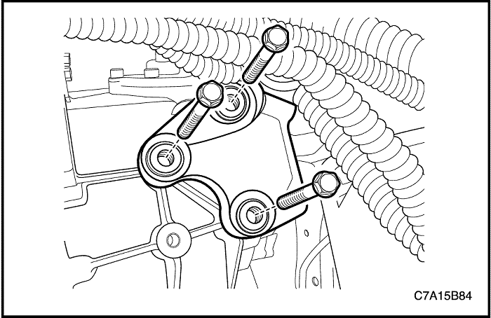
- Remove the upper transaxle-to-engine bolts.
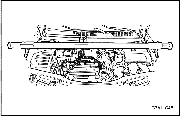
- Install the DW110-060.
- Raise and suitably support the vehicle.
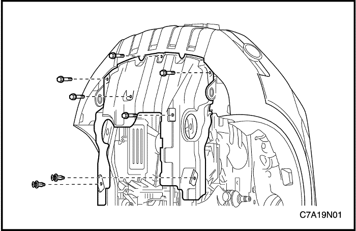
- Remove the engine under cover. Refer to Section 9N, Frame and Underbody.
- Remove the left side dust cover.
- Remove the front exhaust pipe. Refer to Section 1G1, Engine Exhaust - 2.0 Diesel ;
Section 1G2, Engine Exhaust - FAM II 2.4D.
- Carefully remove the cradle from the vehicle. Refer to Section 2C, Front Suspension.
- Remove the drive axle shafts. Refer to Section 3A, Front Drive Axle.
- Remove the shift control cables (1) from the transaxle using a suitable tool.
- Remove the cables (2) from the shift control cable bracket.
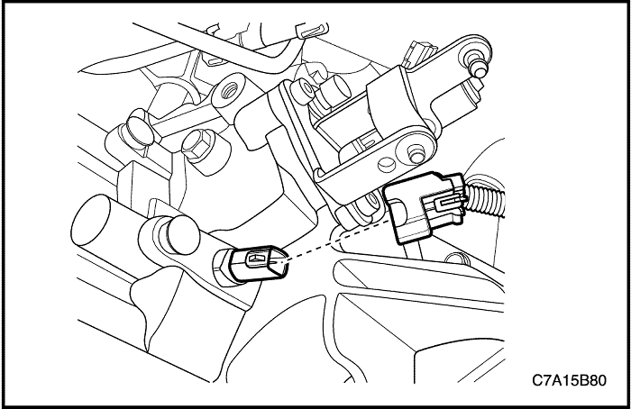
- Disconnect the backup lamp switch electrical wiring connector.
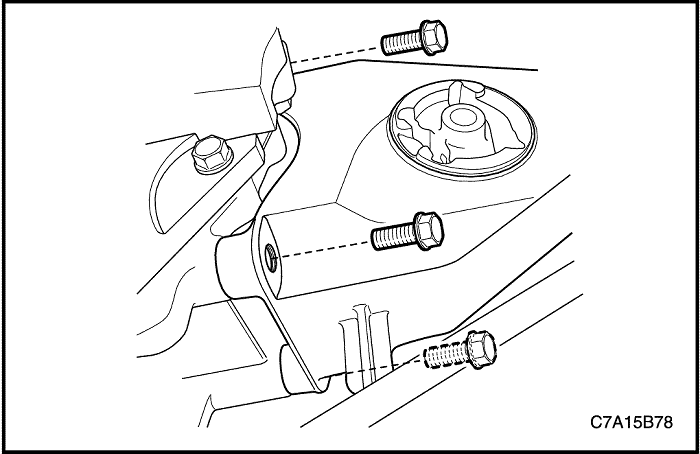
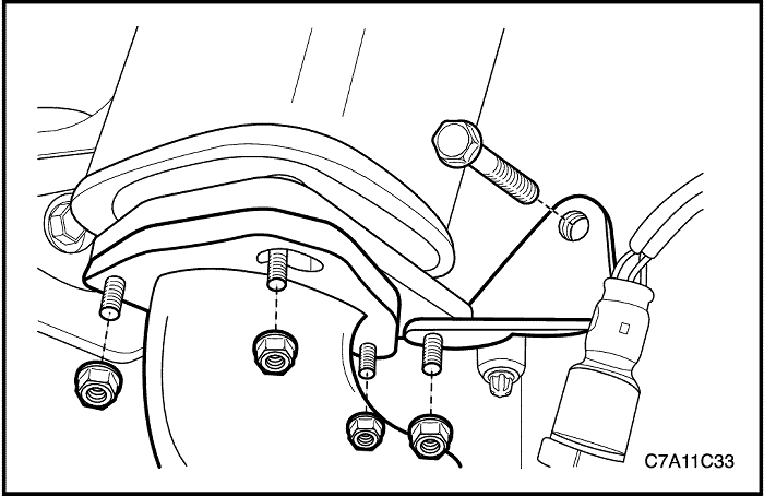
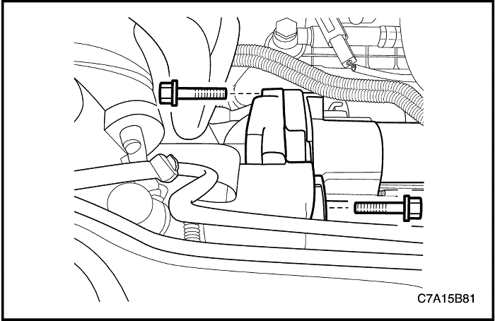
- Remove the front damper bush mounting bolts and the front damper bush.
- Remove the rear transaxle mounting bracket bolts.
- Remove the rear damper bush and the rear transaxle mounting bracket.
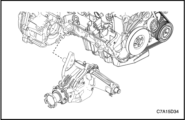
- For AWD, remove the transfer case from the transaxle. Refer to Section 5D, Transfer Case.
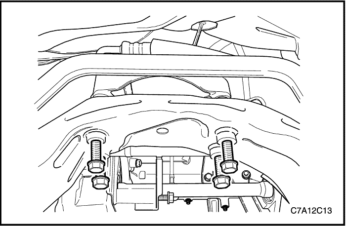
- Remove the starter. Refer to Section 1E1, Engine Electrical - 2.0 Diesel ;
Section 1E2, Engine Electrical - FAM II 2.4D.
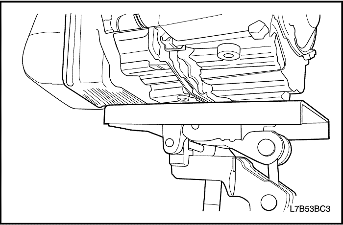
- Support the transaxle assembly using the supporting jack.
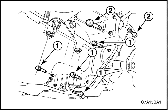
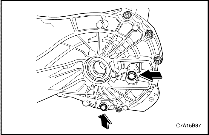
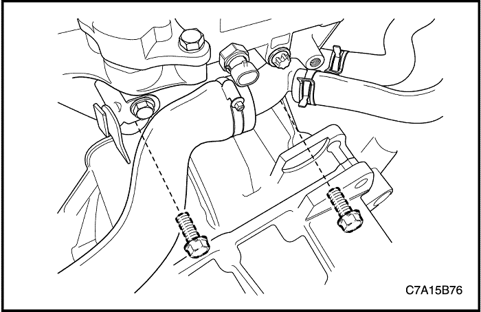
- Remove the oil pan flang-to-transaxle bolts (1).
- Remove the right lower engine-to-transaxle bolts (2) near the front damper bush.
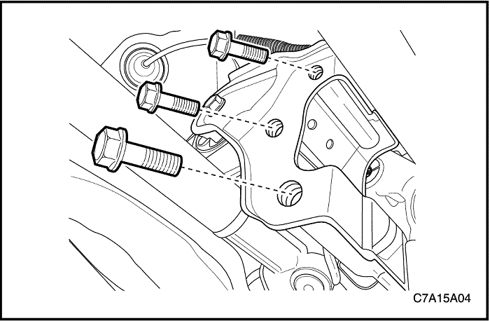
- Remove the left upper transaxle mounting bracket bolts.
- Carefully remove the transaxle assembly from the vehicle.
Installation Procedure
- Install the transaxle into the vehicle and support the transaxle assembly using the supporting jack.
- Install the left upper transaxle mounting bracket bolts.
Tighten
Tighten the left upper transaxle mounting bracket bolts to 50 N•m (37 lb-ft).
- Install the right lower engine-to-transaxle bolts (2) near the front damper bush.
Tighten
Tighten the right lower engine-to-transaxle bolts (2) to 75 N•m (55 lb-ft).
- Install the oil pan flange-to-transaxle bolts (1).
Tighten
Tighten the oil pan flange-to-transaxle bolts (1) 50 N•m (37 lb-ft).
- Remove the transaxle support jack.
- Install the starter. Refer to Section 1E1, Engine Electrical - 2.0 Diesel ;
Section 1E2, Engine Electrical - FAM II 2.4D.
- For AWD, install the transfer case into the transaxle. Refer to Section 5D, Transfer Case.
- Install the rear damper bush and the rear transaxle mounting bracket.
- Install the rear transaxle mounting bracket bolts.
Tighten
Tighten the rear transaxle mounting bracket bolts to 90 N•m (66 lb-ft).
- Install the front damper bush and the front damper bush mounting bolts.
Tighten
Tighten the front damper bush mounting bolts to 50 N•m (37 lb-ft).
- Install the drive axle shafts. Refer to Section 3A, Front Drive Axle.
- Connect the backup lamp switch electrical wiring connector.
- Install the cables (2) to the shift control cable bracket.
- Install the shift control cables(1) to the transaxle.
- Carefully install the cradle into the vehicle. Refer to Section 2C, Front Suspension.
- Install the front exhaust pipe. Refer to Section 1G1, Engine Exhaust - 2.0 Diesel ;
Section 1G2, Engine Exhaust - FAM II 2.4D.
- Install the left side dust cover.
- Install the engine under cover. Refer to Section 9N, Frame and Underbody.
- Lower the vehicle.
- Remove the DW110-060 from the engine.
- Install the upper transaxle-to-engine bolts.
Tighten
For FAM II 2.4D or 2.0S Diesel, tighten the upper transaxle-to-engine bolts to 75 N•m (55 lb-ft).
- Install the pin and the clutch actuator cylinder pipe.
- Install power steering oil reservoir mounting.
- Install the battery and the battery tray. Refer to Section 1E1, Engine Electrical - 2.0 Diesel ;
Section 1E2, Engine Electrical - FAM II 2.4D.
- Execute the air bleeding. Refer to Section 5C, Clutch
- Adjust the shift control cable. Refer to "Shift Control Cable Adjustment"
in this section.
- Check the fluid level. Refer to "Transaxle Fluid Checking Procedure"
in this section.
 |
|
 |
|
| © Copyright Chevrolet Europe. All rights reserved |


