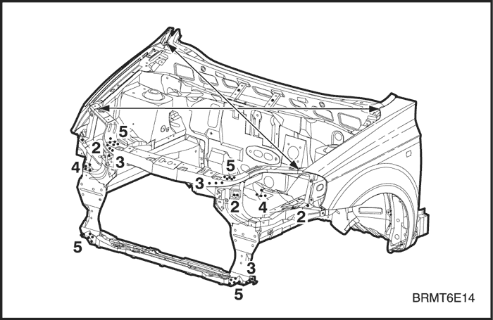
- Remove the related parts.
- Parts to be removed when removing the frontpanel and front wheelhouse.
- Parts on passenger side of dash panel lower whichare especially flammable.
- Instrument panel, wiring harness, related parts andothers.
Note : Remove according to part damaged.
- Roughly pull out and straighten the damaged areato approximately the original shape.
- Attach the car to the frame straightener by tightening the underbody clamps at the horizontalpinch weld points.
- Before cutting off the damaged sections, pull themout so that they are restored to the original shape.
- Roughly cut off the front longitudinal accordingto the extent of damage before roughly pulling outthe damage makes repair of the related partsdifficult.
- Do not pull out more than necessary.
Note : Check the condition of the door and hinges.
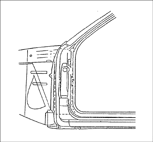
- Peel off the undercoat and sealer.
- Heat the undercoat and sealer at the weldingareas of the damaged parts with a gas torch andpeel off the undercoat and sealer with a steelspatula.
Caution : Be careful not to burn the fittings insidethe passenger compartment when heating.
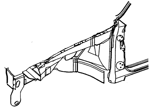
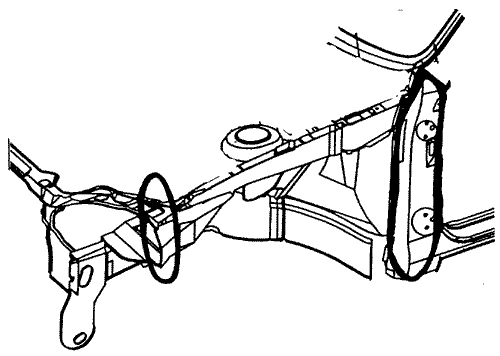
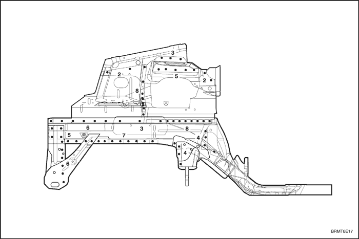
- Cut and pry off the front longitudinal.
Note : It's not necessary to separate the wheelhousefrom the front longitudinal if the wheelhouse is to bereplaced also.
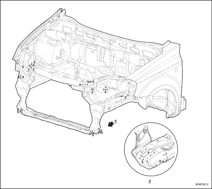
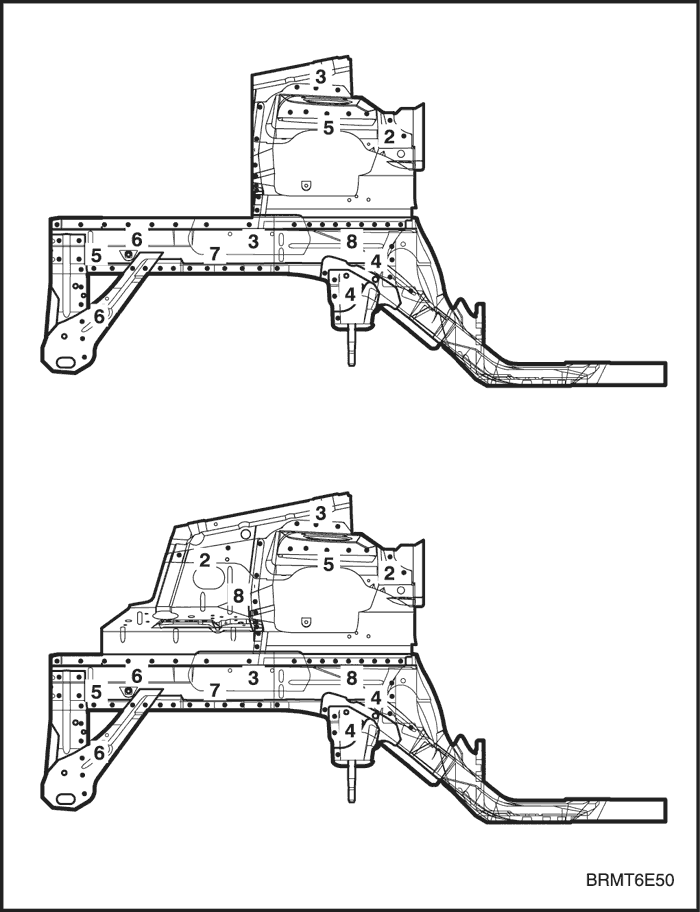
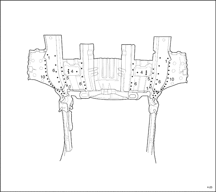
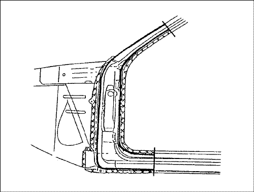
- Center punch around the spot weld imprints on thewheelhouse and other related parts.
- Use the special spot cutter to drill holes at thespot weld nuggets on the center punched areas.
- Cut off the front longitudinal with an air chisel, leaving the welding flanges intact.
- Level and finish the burrs from the pried off spotwelds with a disc sander.
Caution : To prevent eye injury, wear goggles orsafety glasses whenever sanding, cutting, or grinding.


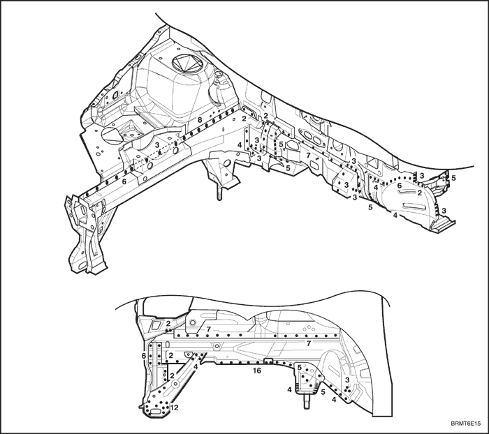
- Mold damaged related parts.
- Fill any holes drilled by welding.
Caution : To prevent eye injury and burns whenwelding, wear an approved welding helmet, glovesand safety shoes.
- Reshape the wheelhouse and other damagedparts and even out the welding flanges with ahammer and dolly.
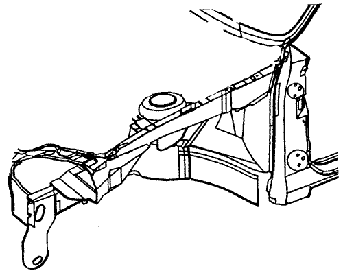
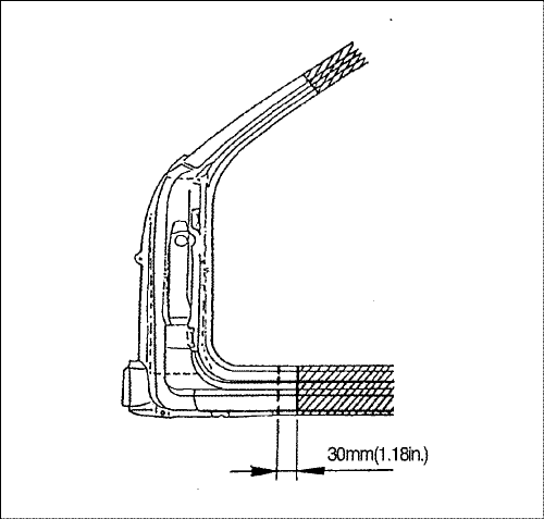
- Cut the new front longitudinal to align it with body,then set the wheelhouse and front panel.
- Cut the new front longitudinal with a hand sawand it will be butt welded.
- Grind both sides of the welding section of the frontlongitudinal and wheelhouse with a disc sanderto remove the paint and expose the steel plate.
Caution : To prevent eye injury, wear goggles orsafety glasses whenever sanding, cutting, or grinding.
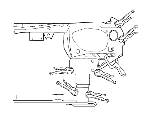
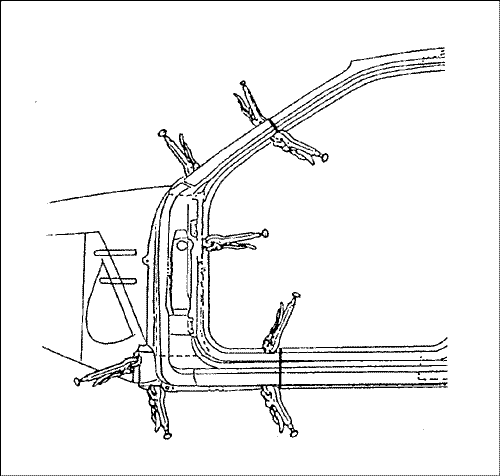
- Tighten the new front longitudinal against remaining parts with the vise grips and pliers.
- Place a jack under the front longitudinal end andsupport it, and measure the positions for correctsetting.
- Set and clamp the front panel in place with thevise grips.
Note : Use of jigs is recommended for correct positions and check that the both front longitudinal andwheelhouse are parallel.
- Tack weld the clamped section for temporary installation.
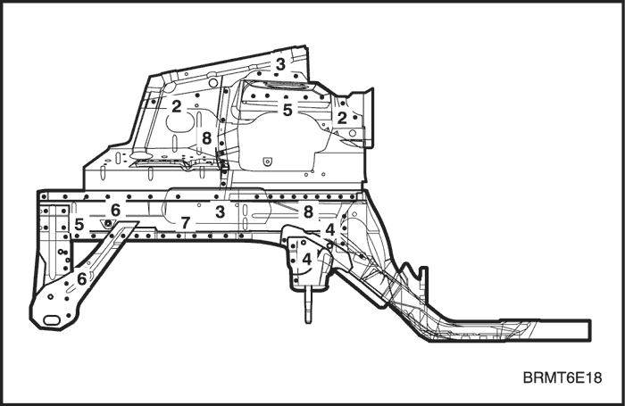
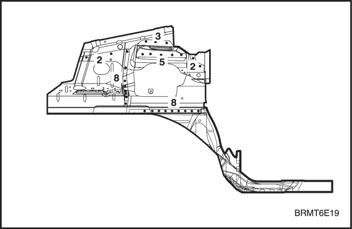
- Perform the main welding.
- Weld as much as possible with the jig stillmounted.
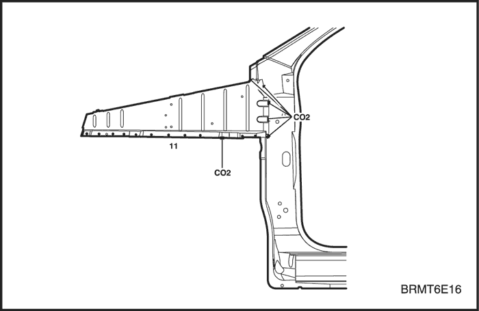
- Make MIG or gas welds at the butt joints at thefront longitudinal, carefully.
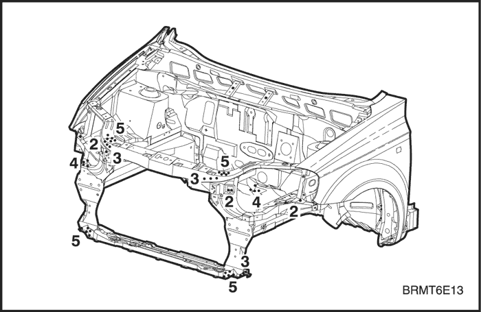
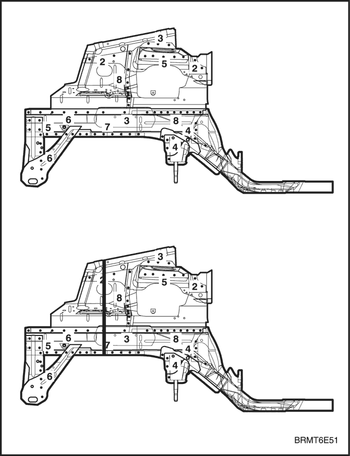
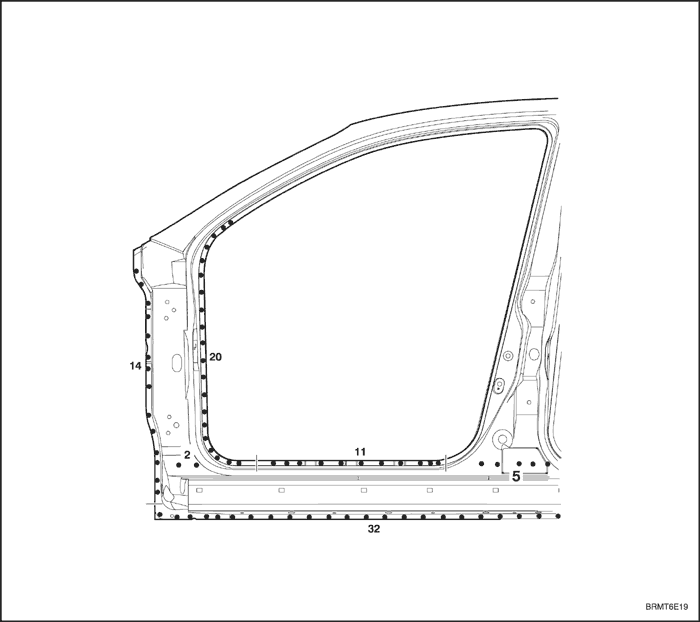
- Spot weld the wheelhouse with the front longitudinal flange areas and front panel.
Caution : To prevent eye injury and burns whenwelding, wear an approved welding helmet, glovesand safety shoes.
- Perform a trial welding first, and check the welding condition.
- Increase the number of spot by 20% for areas tobe spot welded.
- Level the weld beads at the longitudinal butt jointsarea with disc sander.
- Make the stiffener(Thickness: 2.8 mm Min., Width:80 mm) according to the form of longitudinal buttjoint areas and weld the stiffener at the longitudinal butt joint areas with MIG welder.
- Finish the welding areas.
- Level the gas or MIG welded areas with discsander.
- Use a hammer and dolly to even out the wheelhouse and longitudinal flanges for a close fit.
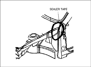
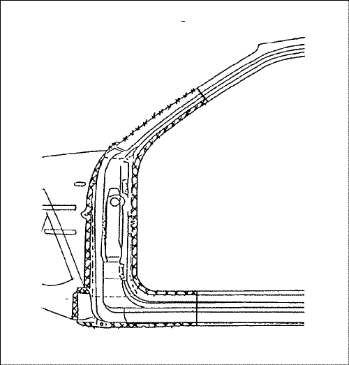
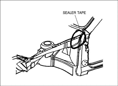
- Apply the sealer.
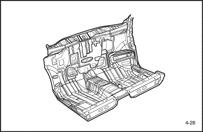
- Apply the sealer to the joint areas of the dashpanel lower and floor panel areas.
- Apply the undercoat.
- Undercoat to the joint and overlapped areas ofthe front floor, longitudinal under side and theinside of front, rear wheelhouse.
- Apply the paint.
- CAUTION
- Ventilate when spraying paint. Most paint containssubstances that are harmful if inhaled or swallowed. Read the paint label before opening paint container.
- Avoid contact with skin. Wear an approved respirator, gloves, eye protection and appropriateclothing when painting.
- Paint is flammable. Store in a safe place, andkeep it away from sparks, flames or cigarettes.
- Coating the anti-rust agents.
- Coating the anti-rust agents to the end of frontpanel side and the front door hinge areas.
- Install the related parts.
- Clean the passenger compartment.
- Wiring harness, instrument panel and relatedparts.
- Parts of the passenger compartment.
- Chassis components.
- Engine, radiator and related parts.
- Aircon condenser and related parts.
- Head lamps and fenders.
- Heed, radiator grill, and bumper.
- Others.
- Install in the reverse order in which they were removed.
Note : After install the all related parts, rub in greaseo the moving parts and replenish cooling liquid,break oil, aircon gas and others.
- Check and adjust
- Check clearances and level differences.
- Check the hood locking and unlocking condition.
- Adjust the head lamp aim.
- Check all operation.
- Check for gas, oil and liquid leaks.
- Check for water leaks in the passenger compartment.
Note : Use specified check sheet for operationcheck properly.