- Remove the related parts.
- Parts to be removed when removing the backpanel.
- Rear seat belt and rear seat.
- Muffler, fuel tank and related parts.
- Chassis parts.
- Other related parts.
Caution : Do not smoke while working near the fuelsystem. Keep open flame away from the fuel system. If necessary, remove the fuel tank and off lines.
- Roughly pull out and straighten the damaged area.
- Check the damage and roughly pull out and repair the related back panel, side panel, wheelhouse inner, rear longitudinal and other damagedparts with the frame straightener before removing the extension rear floor panel, rear floor paneand back panel.
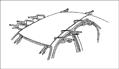
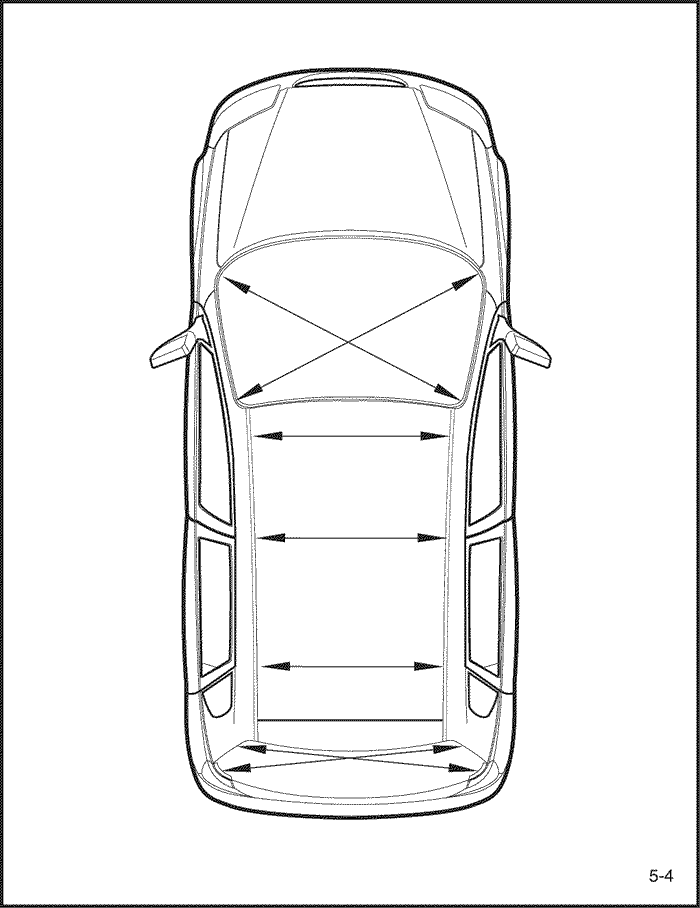
- Attach the car to the frame straightener by tightening the underbody clamps located at the jackup designated points on the bottom of the framedoor opening.
Note : Measure in reference to the dimensions onthe body repair chart.
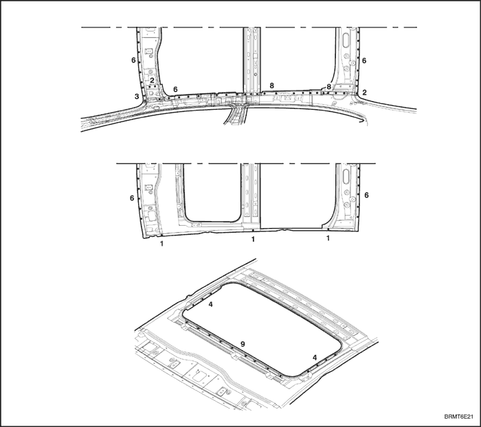
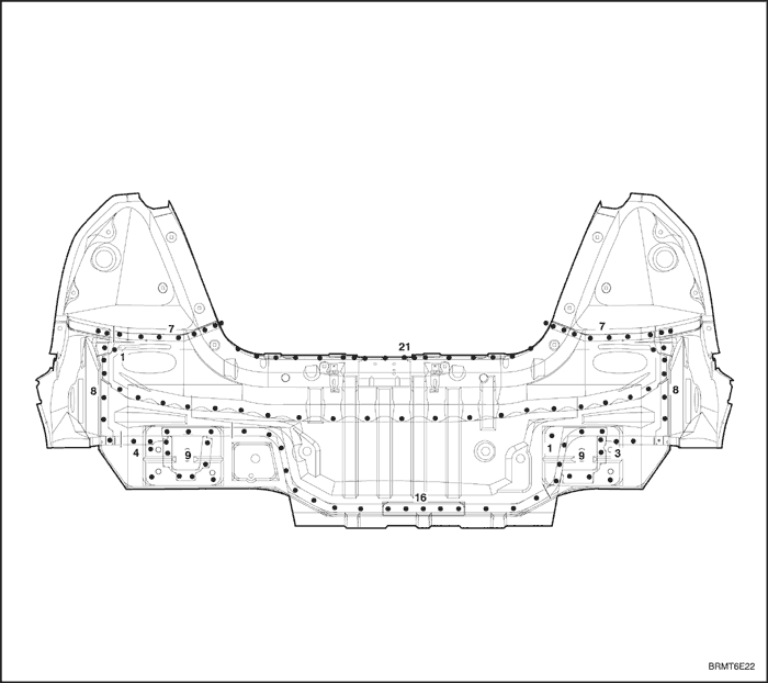
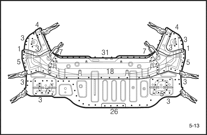
- Cut and pry off the back panel.
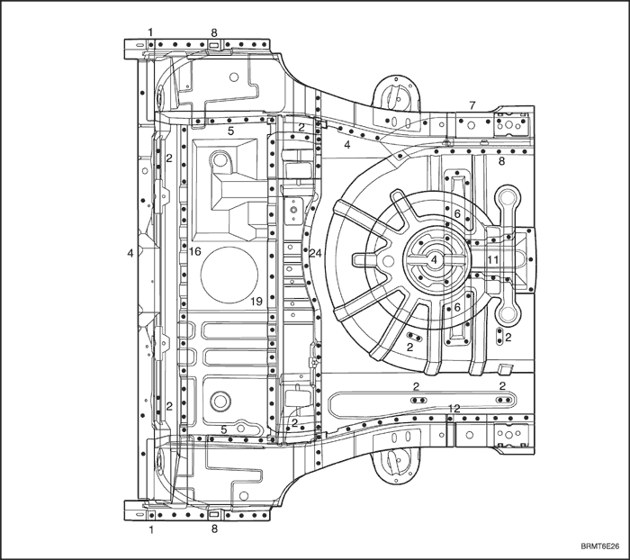
- The back panel to be cut and pried off when removing the back panel.
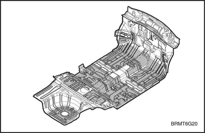
- Cut and pry off the rear floor and extension rear floorpanel.
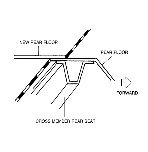
- Cut off the rear floor and extension rear floor witha gas torch or air chisel leaving the spot weldedflanges of the rear longitudinal along the bold linein the figure below.
Note : Cut the rear floor 15mm(0.59in.) from weldedflange of the cross member rear seat.
- Center punch around the spot weld imprints withthe rear longitudinal, extension rear longitudinaland web plate.
- Use the special spot cutter to drill holes at thespot weld nuggets on the center punched areas.
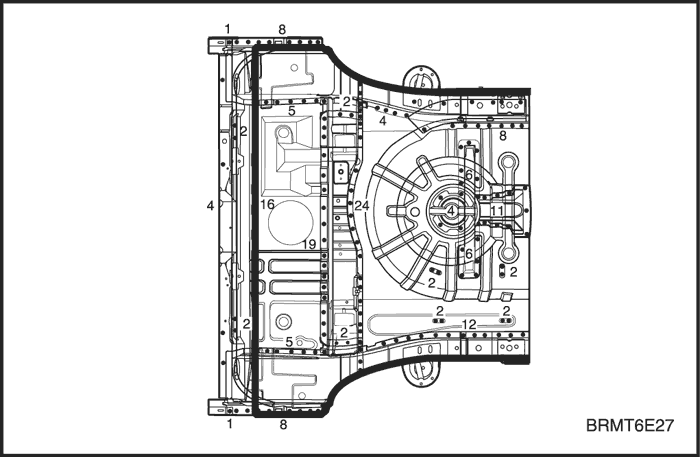


Note : When drilling holes be careful not to drill downto the rear longitudinal, extension rear longitudinaland web plate themselves.
- Cut and pry off the remaining rear floor and extension rear floor panel with an air chisel, leavingthe welding flanges intact.
- Level and finish the burrs from the pried off spotwelds with disc sander and repair all cracks, holesor other defects by welding also repair the rearlongitudinal and extension rear longitudinal if necessary.
Caution : To prevent eye injury, wear goggles orsafety glasses whenever sanding, cutting, or grinding.
- Peel off the undercoat and sealer.
- Heat the undercoat and sealer at the weldingareas with a gas torch and peel off the undercoatand sealer with a steel spatula.
- Mold damaged related parts.
- Use a hammer and dolly to mold damaged areasof the rear longitudinal and extension rear longitudinal.
- Even out the welding flanges with a hammer anddolly.
- Fill any holes drilled by welding.
Caution : To prevent eye injury and burns whenwelding, wear an approved welding helmet, glovesand safety shoes.
- Level and finish the burrs from the pried off spotwelds with disc sander.
- Sand off the paint and undercoat from both sidesof the flange to be welded.
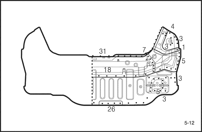
- Cut the new rear floor to align it with the body, thenset the new rear floor and extension rear floor.
- Cut the new part so it overlaps the cross member rear seat by approximately 40mm(1.57in.).
- Grind both sides of the welding section of the rearfloor and extension rear floor with a disk sanderto remove the paint and expose the steel plate.
Caution : To prevent eye injury, wear goggles orsafety glasses whenever sanding, cutting, or grinding.
- Set and clamp the new panel in place with the vise grips.
Note : Use of jigs is recommended for correct positions and check that the both rear logitudinal is parallel.
- Tack weld the clamped section for temporary installation.
Caution : To prevent eye injury and burns whenwelding, wear an approved welding helmet, glovesand safety shoes.
- Remove the vise grips and temporarily install therear panel, then check the alignment, level differences and outer appearance.
- Remove the main welding.
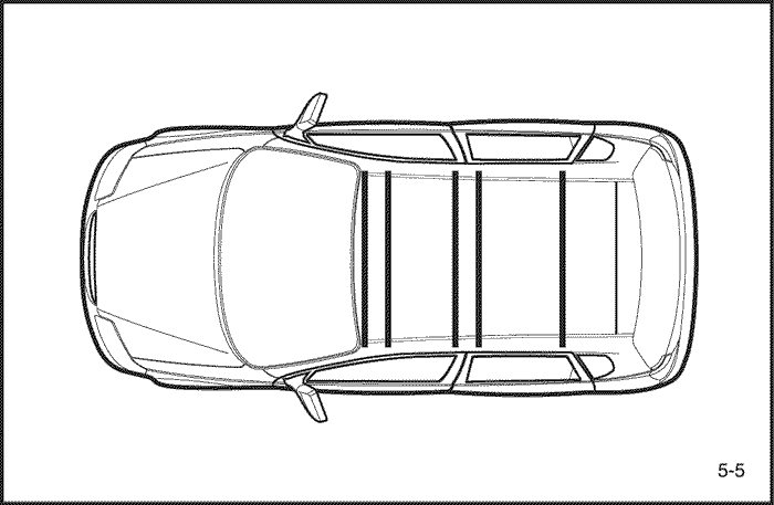
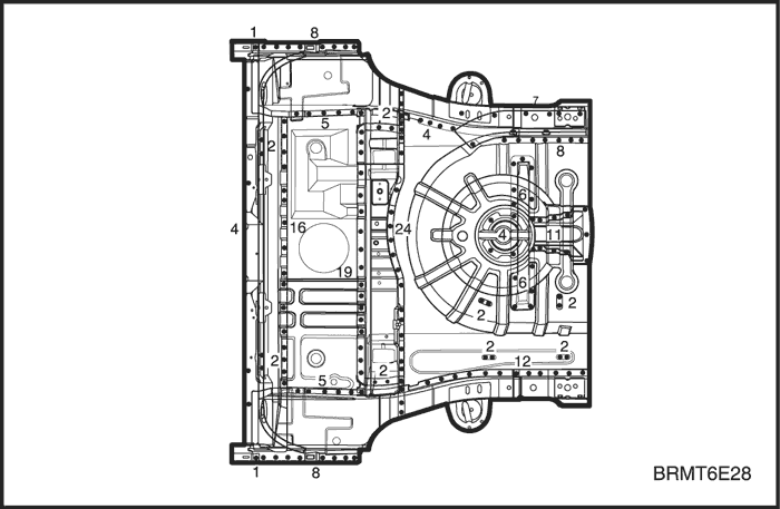
- Weld the rear floor and cross member rear seatwith a MIG welder fillet weldings as shown.
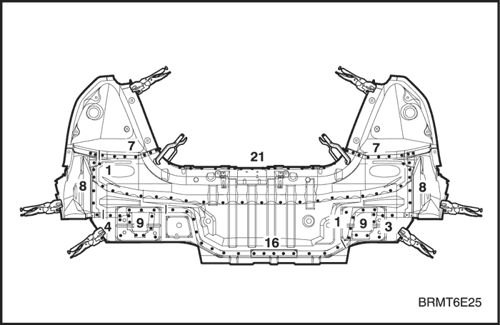
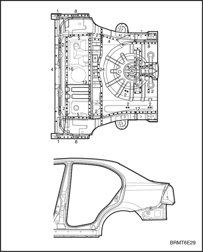
- Spot weld the rear floor and extension rear floorwith rear longitudinal flange areas and web plateflanges as shown.
Caution : To prevent eye injury and burns whenwelding, wear an approved welding helmet, glovesand safety shoes.
- Perform a trial welding first, and check the welding condition.
- Increase the number of spot by 20% for areas tobe spot welded.
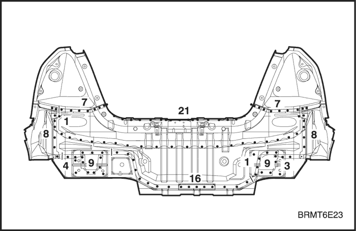
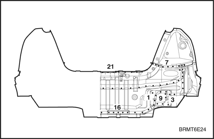
- Weld the back panel
- The back panel to be welded when replacementthe back panel.
- Finish the welding area.
- Level the MIG welded areas with a disc sander,then even out high areas with a hammer beingcareful not to deform them.
Caution : To prevent eye injury, wear goggles orsafety glasses whenever standing, cutting, or grinding.
- Use a hammer and dolly to even out the spotwelded areas for a close fill the flange surfacetogether.
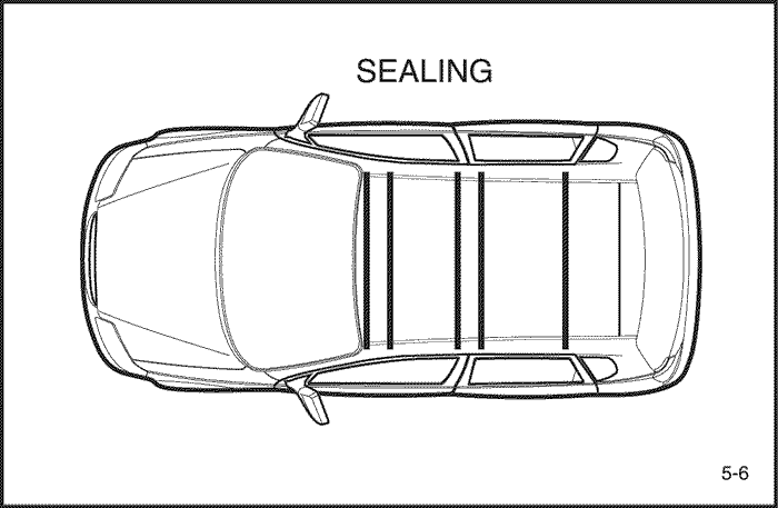
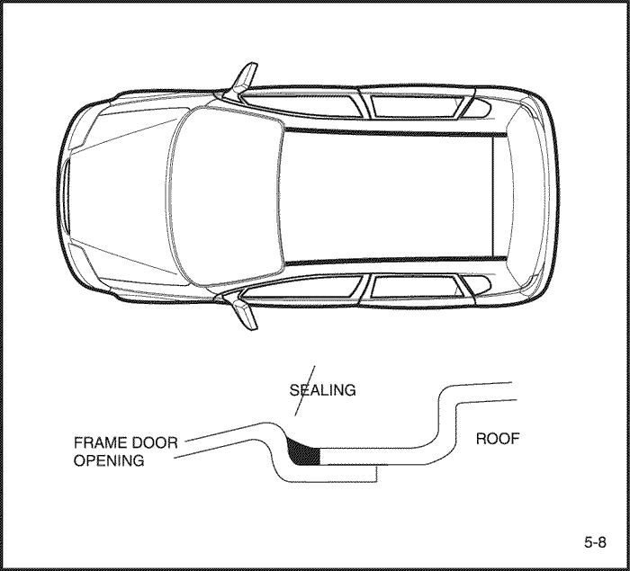
- Apply the sealer.
- Apply the sealer at the overlapped areas of therear floor and extension rear floor, and weldedsurfaces of the matching panel and all sealinggaps completely.
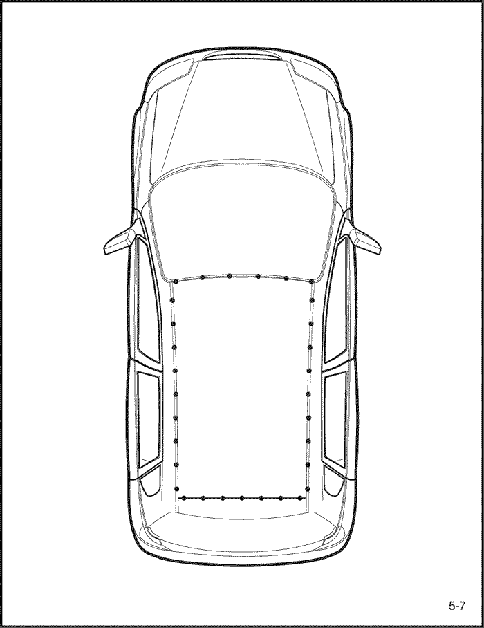
- Apply the undercoat.
- Undercoat to the rear wheelhouse and designatedrear floor.
- Apply the paint
- CAUTION
- Ventilate when spraying paint. Most paint containssubstances that are harmful if inhaled or swallowed.Read the paint label before opening paint container.
- Avoid contact with skin. Wear an approved respirator, gloves, eye protection and appropriateclothing when painting.
- Paint is flammable. Store in a safe place, andkeep it away from sparks, flames or cigarettes.
- Apply the deadner.
- Clean the passenger and trunk compartment.
- Apply the deadner to the surface of rear floor andextension rear floor.
- Install the related parts.
- Install in the reverse order in which they were removed.
- Check and adjust
- Check clearances and level differences.
- Check the trunk locking and unlocking condition.
- Check all operation.
- Check for water leaks in the trunk compartment.
Note : Use specified check sheet for operationcheck properly.