MAINTENANCE AND REPAIR
ON-VEHICLE SERVICE
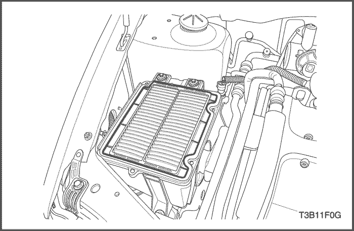


Air Filter Element
Removal & Installation Procedure
- Remove the air filter upper housing.
- Replace the air filter element.
Notice : Before replacing a new one, check the maintenance interval and the quality of the air cleaner element.
Tighten
Tighten the air filter upper housing bolts to 2 N•m (1.5 lb-ft).
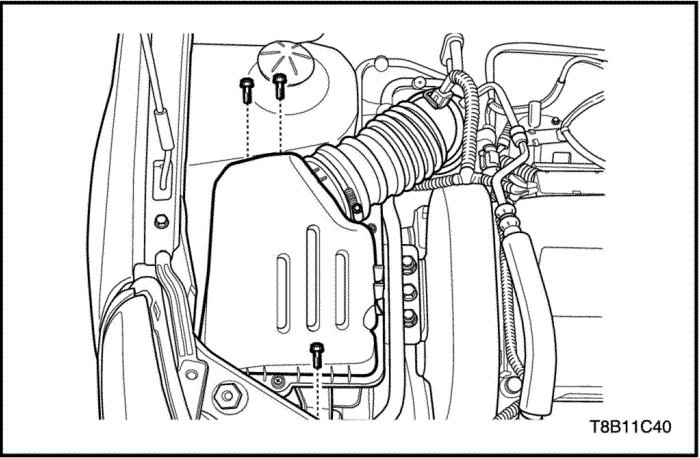
Air Cleaner Assembly
Removal & Installation Procedure
- Loosen the clamp and disconnect outlet tube from the air cleaner upper housing.
- Remove the air cleaner assembly bolts.
Tighten
Tighten the air cleaner assembly bolts to 6 N•m (4.4 lb-ft).
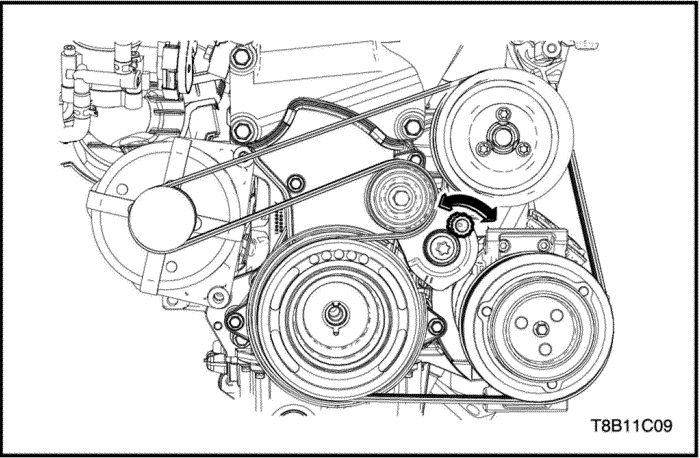
Accessory Belt and Tensioner
Removal Procedure
- Rotate the tensioner star-nut and remove the accessory belt.
Notice : To remove the power steering pump belt, do remove the accessory belt in advance.
- Remove the power steering belt. Refer to Section 6B, Power Steering Pump.
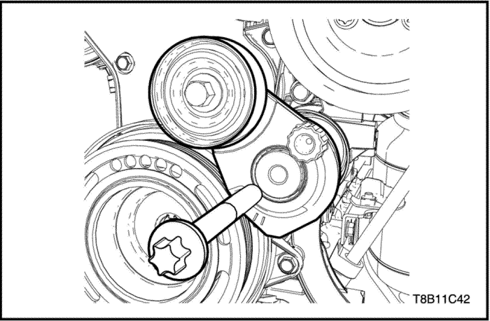
- Remove the accessory belt tensioner.
Installation Procedure
- Install the accessory belt tensioner.
Tighten
Tighten the accessory belt tensioner bolt to 50 N•m (36.8 lb-ft).
- Install the power steering belt. Refer to Section 6B, Power Steering Pump.
- Rotate the tensioner star-nut and install the accessory belt.
- Install the engine front shield at the position of right front wheel.
Intake Manifold
Removal Procedure
Caution : Do not remove when the engine is hot. It may cause damage and can be injured.
- Disconnect the battery negative cable.
- Release the fuel pressure. Refer to Section 1F2, Engine Controls - 1.4 DOHC - G14D.
- Remove the air cleaner assembly. Refer to “Air Cleaner Assembly”
in this section.
- Remove the power steering pressure pipe clamp from the intake manifold. Refer to Section 6A, Power Steering System.
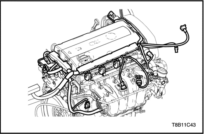
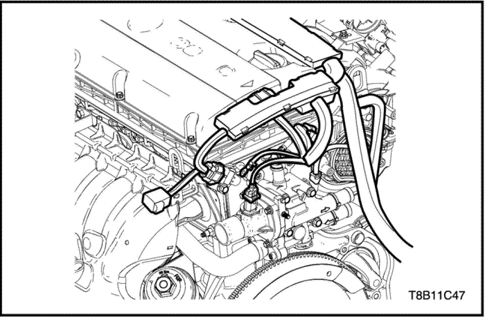
- Disconnect the related sensor and actuator connectors and the pull engine wiring harness aside.
- Intake Air Temperature Sensor Connector
- A/C Pressure Sensor(ACP) Connector
- Cam Position Solenoid Valve Connector
- Electric Throttle Controller(ETC) Connector
- Manifold Air Pressure(MAP) Sensor Connector
- EVAP Solenoid Valve Connector
- Injector Connectors
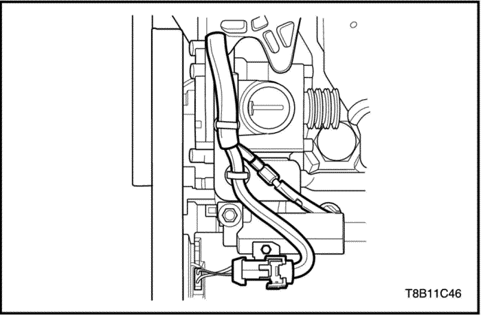
- Disconnect the fuel line from the fuel rail.
- Disconnect the ETC coolant inlet/outlet hoses and then pull it aside.
- Remove the PCV hose from the ETC.
- Remove the cylinder head cover. Refer to “Cylinder Head Cover”
in this section.
- Remove the electric throttle controller(ETC). Refer to Section 1F2, Engine Controls - 1.4 DOHC - G14D.
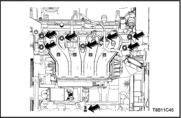
- Remove the intake manifold with the gasket.
Installation Procedure
Caution : Do not reuse the intake manifold gasket.
- Install the intake manifold with the new gasket.
Tighten
- Tighten the intake manifold bolts to 20 N•m (14.7 lb-ft).
- Tighten the intake manifold lower bracket bolt to 8 N•m (70.8 lb-in).
- Install the electric throttle controller(ETC). Refer to Section 1F2, Engine Controls - 1.4 DOHC - G14D.
- Install the cylinder head cover. Refer to “Cylinder Head Cover”
in this section.
- Install the PCV hose to the ETC.
- Connect the ETC coolant inlet/outlet hoses.
- Connect the fuel line to the fuel rail.
- Connect the related sensor and actuator connectors.
- A/C Pressure Sensor(ACP) Connector
- Cam Position Solenoid Valve Connector
- Electric Throttle Controller(ETC) Connector
- Manifold Air Pressure(MAP) Sensor Connector
- EVAP Solenoid Valve Connector
- Injector Connectors
- Install the power steering pressure pipe clamp to the intake manifold. Refer to Section 6A, Power Steering System.
- Install the air cleaner assembly. Refer to “Air Cleaner Assembly”
in this section.
- Connect the battery negative cable.
Exhaust Manifold
Removal Procedure
Caution : Do not remove when the engine is hot. It may cause damage and can be injured.
- Disconnect the battery negative cable.
- Disconnect the upper oxygen sensor connector.
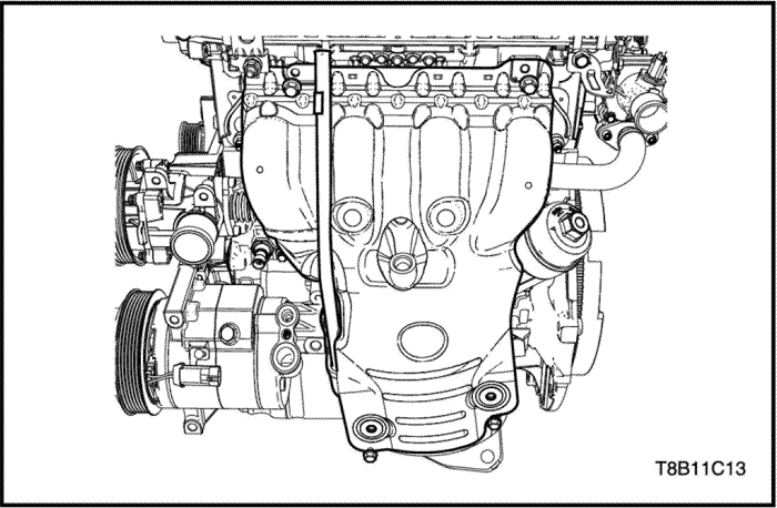
- Remove the exhaust manifold heat shield with engine oil indicator tube.
- Remove the exhaust front pipe. Refer to Section 1G, Exhaust System.
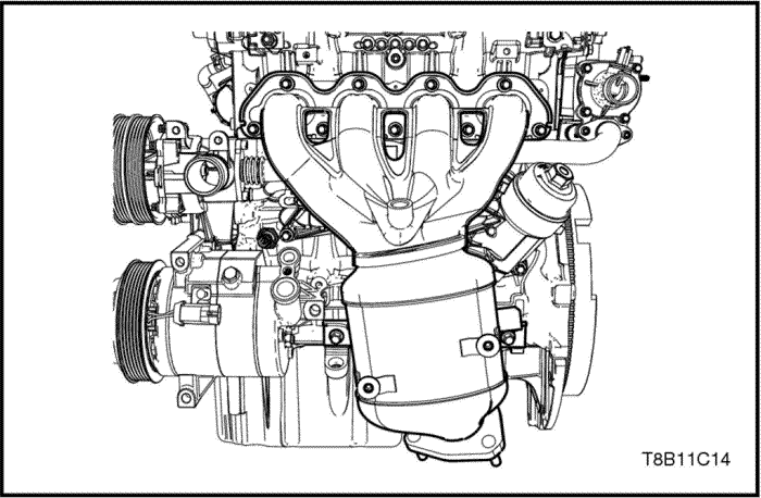
- Remove the exhaust manifold with the gasket.
Notice : The exhaust manifold and the catalytic converter are one-piece.
Installation Procedure
Caution : Check the exhaust gasket surface whether cracks or damages or not.
- Install the exhaust manifold with the gasket.
Tighten
- Tighten the exhaust manifold nuts to 20 N•m (14.7 lb-ft).
- Tighten the exhaust manifold lower bracket bolts to 20 N•m (14.7 lb-ft).
- Install the exhaust front pipe. Refer to Section 1G, Exhaust System.
- Install the exhaust manifold heat shield with engine oil indicator tube.
Tighten
Tighten the heat shield bolts to 8 N•m (70.8 lb-in).
- Connect the upper oxygen sensor connector.
- Connect the batter negative cable.
Cylinder Head Cover
Removal Procedure
- Disconnect the battery negative cable.
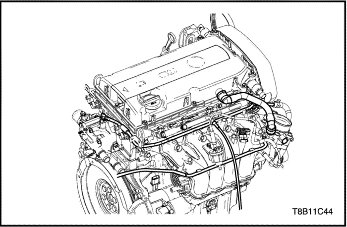
- Disconnect the related sensor and actuator connector and pull engine wiring harness aside.
- Oil Switch Wiring Connector
- A/C Compressor Connector
- Manifold Air Temperature(MAT) Sensor Connector
- A/C Pressure(ACP) Sensor Connector
- Cam Position Solenoid Valve Connectors(Right/Left)
- Manifold Air Pressure(MAP) Sensor Connector
- EVAP Canister Purge Solenoid Valve Connector
- Injectors Connectors
- Ignition Coil Connector
- Camshaft Position Sensor(CPS) Connectors(Right/Left)
- Remove the ignition coil. Refer to Section 1F2, Engine Controls - 1.4 DOHC - G14D.
- Detach the PCV clips from the PCV hose.
- Remove the PCV hose from the cylinder head cover.
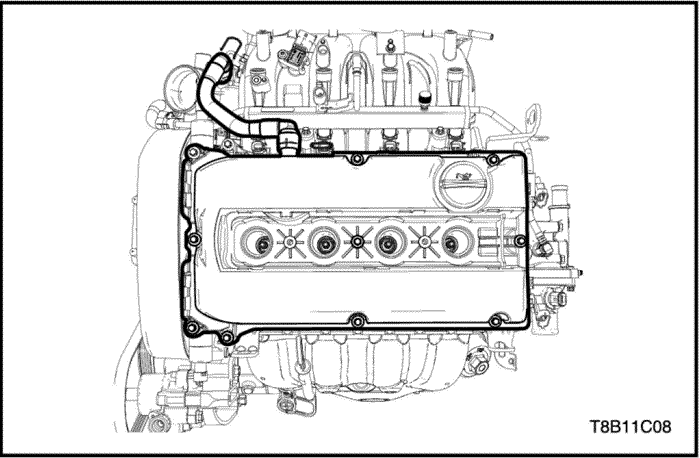
- Unscrew the cylinder head cover bolts.
- Remove the cylinder head cover.
Installation Procedure
Notice : Check and Confirm the damage or crack of the cylinder head gasket. If damaged or cracked, replace the new one.
- Install the cylinder head with the gasket.
- Screw the cylinder head cover bolts.
Tighten
Tighten the cylinder head cover bolts to 8 N•m (70.8 lb-in).
- Install the PCV hose to the cylinder head cover.
- Attach the PCV clips to the PCV hose.
- Install the engine wiring harness and connect the related sensor and actuator connector.
- Oil Switch Wiring Connector
- A/C Compressor Connector
- Manifold Air Temperature(MAT) Sensor Connector
- A/C Pressure(ACP) Sensor Connector
- Cam Position Solenoid Valve Connectors(Right/Left)
- Manifold Air Pressure(MAP) Sensor Connector
- EVAP Canister Purge Solenoid Valve Connector
- Ignition Coil Connector
- Camshaft Position Sensor(CPS) Connectors(Right/Left)
- Connect the battery negative cable.
| © Copyright Chevrolet Europe. All rights reserved |


