SECTION 1D
ENGINE COOLING
Caution : ENGINE COOLING
CAUTION: Disconnect the negative battery cable before removing or installing any electrical unit or when a tool or equipment could easily come in contact with exposed electrical terminals. Disconnecting this cable will help prevent personal injury and damage to the vehicle. The ignition must also be in LOCK unless otherwise noted.
SPECIFICATIONS
Cooling System Specification
|
Application
|
Description
|
Unit
|
Standard
|
|
Cooling System
|
Cooling Type
|
-
|
Forced Water Cooling
|
|
Coolant
|
Type
|
-
|
Dexcool
|
|
Capacity
|
L
|
5.2L (1.2D)/6.3L (1.4D)
|
|
Thermostat
|
Type
|
-
|
Wax Pellet (B12D)
Electric Controlled (G14D)
|
|
Temperature (Opened Initially)
|
°C (°F)
|
87 °C (189 °F) - 1.2D 105 °C (221 °F) - 1.4D
|
|
Temperature (Completely Opened)
|
°C (°F)
|
102 °C (216 °F) - 1.2D 120 °C (248 °F) - 1.4D
|
|
Temperature (Completely Closed)
|
°C (°F)
|
82 °C (180 °F) - 1.2D 95 °C (203 °F) - 1.4D
|
|
Stroke (Completely Opened)
|
mm (in.)
|
8 (0.31) : 1.2D/1.4D
|
|
Cooling Fan
|
Type
|
-
|
Electrical Single Fan
|
|
Number of Blade (with A/C)
|
EA
|
5 (7)
|
|
Diameter
.
|
mm (in.)
.
|
With A/C (1.2D) : 362 (14.2) (1.4D) : 366 (14.4)
Without A/C (1.2D) : 320 (12.6) (1.4D) : 300 (11.8)
|
|
ON Temperature at Low Speed
|
°C (°F)
|
93 (199.4)
|
|
OFF Temperature at Low Speed
|
°C (°F)
|
90.75 (195.35) : 1.2 DOHC, 90 (194)
|
|
ON Temperature at High Speed
|
°C (°F)
|
96.75 (206.15) : 1.2 DOHC, 97 (206.6)
|
|
OFF Temperature at High Speed
|
°C (°F)
|
94.5 (202.1) : 1.2 DOHC, 94 (201.2)
|
|
Surge Tank
|
Open Pressure of the Pressure Valve
|
kPa
|
1.2 DOHC : 120, 1.4 DOHC : 120 ~ 150
|
|
Open Pressure of the Vacuum Valve
|
kPa
|
10 kPa
|
|
Water Pump
|
Type
|
-
|
Centrifugal
|
|
Impeller Diameter
|
mm (in.)
|
56 (2.20)
|
|
Number of Impeller Blade
|
EA
|
1.2D : 7, 1.4D : 11
|
|
Radiator
|
Type
|
-
|
Cross Flow
|
|
Core Width
|
mm
|
600
|
|
Core Height
|
mm
|
415
|
|
Core Depth
|
mm
|
16
|
Fastener Tightening Specifications
|
Application
|
N•m
|
Lb-Ft
|
Lb-In
|
|
Water Pump Mounting Bolts
|
10
|
-
|
89
|
|
Electric Cooling Fan Motor Nut
|
3.2
|
-
|
28
|
|
Electric Cooling Fan Motor Retaining Screws
|
4
|
-
|
35
|
|
Electric Cooling Fan Assembly Mounting Bolts
|
4
|
-
|
35
|
|
Engine Coolant Temperature Sensor
|
20
|
15
|
-
|
|
Negative Battery Terminal Retainer Bolt
|
15
|
11
|
-
|
|
Surge Tank Attaching Bolt
|
10
|
-
|
89
|
|
Thermostat Housing Mounting Bolts (1.2D)
|
10
|
-
|
89
|
|
Thermostat Housing Retaining Bolts (1.4D)
|
8
|
5.9
|
-
|
|
Upper Left Radiator Retaining Bolt
|
10
|
-
|
89
|
|
Upper Right Radiator Retaining Bolt
|
10
|
-
|
89
|
DIAGNOSIS
Thermostat Test
- Remove the thermostat from the vehicle. Refer to "Thermostat" in this section.
- Make sure the valve spring is tight when the thermostat is fully closed. If the spring is not tight, replace the thermostat.
- Suspend the thermostat and a thermometer in a pan of 50/50 mixture of ethylene glycol and water. Do not let the thermostat or the thermometer rest on the bottom of the pan because the uneven concentration of heat on the bottom could result in inaccurate temperature measurements.
- Heat the pan on a burner.
- Use the thermometer to measure the temperature of the heated solution.
- The thermostat should begin to open at 87 °C (1.2D)/105 °C (1.4D) and it should be fully open at 102 °C (1.2D)/120 °C (1.4D). If it does not open at these temperatures, replace the thermostat.
- The thermostat wiring harness connector controls the heater and have two pins. (1.4D Only)
- The specification of the resistance between the two pins should be 15.2 ± 1.5 (Ω).
- The specification of the resistance between each pin and thermostat housing should be ∞ (Ω).
Cooling Systen Diagnosis
Engine Overheats
|
Checks
|
Action
|
|
Check for a loss of the coolant.
|
Add the coolant.
|
|
Check for a weak coolant solution.
|
Confirm that the coolant solution is a 50/50 mixture of ethylene glycol and water.
|
|
Check the front of the radiator for any dirt, any leaves, or any insects.
|
Clean the front of the radiator.
|
|
Check for leakage from the hoses, the water pump, the heater, the thermostat housing, the radiator, the core plugs, or the head gasket.
|
Replace any damaged components.
|
|
Check for a faulty thermostat.
|
Replace a damaged thermostat.
|
|
Check for retarded ignition timing.
|
Perform a code diagnosis using the engine control module (ECM) for a vehicle with a manual transaxle. Confirm the integrity of the timing belt.
|
|
Check for an improperly operating electric cooling fan.
|
Replace the electric cooling fan.
|
|
Check for radiator hoses that are plugged or rotted.
|
Replace any damaged radiator hoses.
|
|
Check for a faulty water pump.
|
Replace a faulty water pump.
|
|
Check for a faulty surge tank cap.
|
Replace a faulty surge tank cap.
|
|
Check for a cylinder head or an engine block that is cracked or plugged.
|
Replace a faulty water pump.Repair the damaged cylinder head or the damaged engine block.
|
Loss of Coolant
|
Checks
|
Action
|
|
Check for a leak in the radiator.
|
Replace a damaged radiator.
|
|
Check for a leak in the following locations:
|
Replace the following parts:
|
|
Check for the following loose or damaged parts:
- Radiator hoses.
- Heater hoses.
- Connections.
|
Reseat the hoses.
Replace the hoses or the clamps.
|
|
Check for leaks in the water pump seal.
|
Replace the water pump seal.
|
|
Check for leaks in the water pump gasket.
|
Replace the water pump gasket.
|
|
Check for an improper cylinder head torque.
|
Tighten the cylinder head bolts to specifications.
Replace the cylinder head gasket, if needed.
|
|
Check for leaks in the following locations:
- Intake manifold.
- Cylinder head gasket.
- Cylinder block plug.
- Heater core.
- Radiator drain plug.
|
Repair or replace any components, as needed, to correct the leak.
|
Engine Fails to Reach Normal Operating Temperature or Cool Air from the Heater
|
Checks
|
Action
|
|
Check to determine if the thermostat is stuck open, or if it is the wrong type of thermostat.
|
Install a new thermostat of the correct type and heat range.
|
|
Check the coolant level to determine if it is below the MIN mark on the surge tank.
|
Add sufficient coolant to raise the fluid to the specified mark on the surge tank.
|
COMPONENT LOCATOR
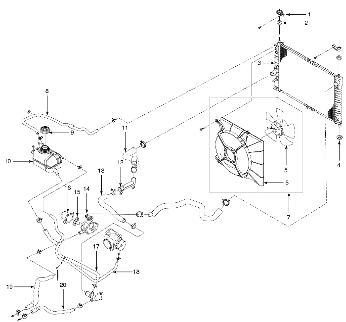
Cooling System - 1.2L DOHC -
- Radiator Mounting Bracket
- Radiator Upper Bumper
- Radiator
- Radiator Lower Bumper
- Cooling Fan
- Cooling Fan Lower Hose
- Blower Assembly
- Coolant Hose (Radiator & Surge Tank)
- Coolant Surge Tank Cap
- Coolant Surge Tank
- Coolant Hose (Coolant Pipe & Radiator)
- Coolant Pipe
- Coolant Hose (Coolant Pipe & Coolant Inlet Cap)
- Coolant Outlet Case
- Thermostat
- Thermostat Housing
- Coolant Hose (Surge Tank & Coolant Inlet Cap)
- Coolant Hose (Throttle Body & Surge Tank)
- Heater Core Coolant Return Hose
- Heater Core Coolant Feeding Hose
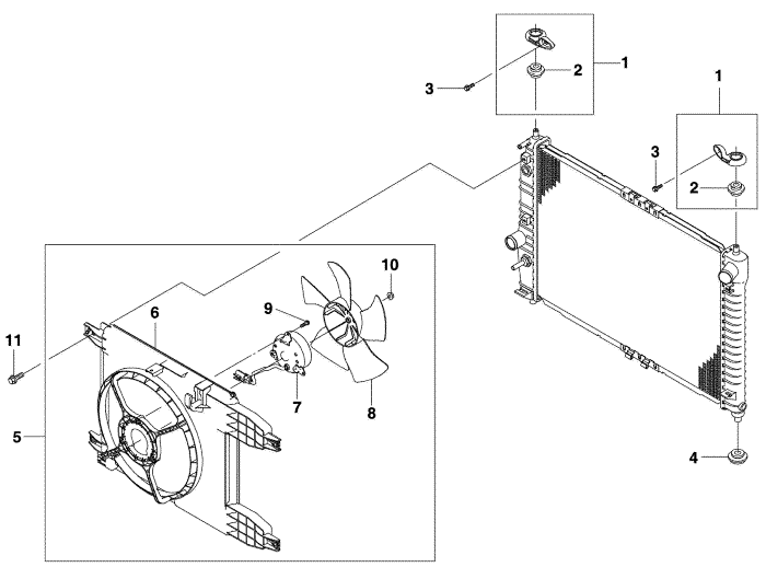
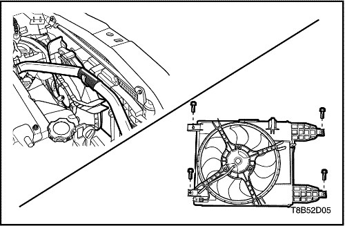
Cooling Fan - 1.4L DOHC - G14D -
- Radiator Upper Bracket
- Radiator Upper Bumper
- Bolt
- Radiator Lower Bumper
- Main Fan
- Shroud
- Motor
- Fan
- Screw
- Nut
- Bolt
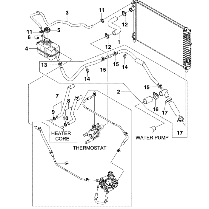
Cooling System - 1.4L DOHC - G14D -
- Radiator Upper Hose
- Radiator Upper Hose
- Radiator & Surge Tank Hose
- Surge Tank
- Surge Tank Cap
- Nut
- Heater Feeding Hose
- Heater Return Hose
- Clip
- Clip
- Clip
- Clip
- Clip
- Clip
- Clip
- Clip
- Clip
MAINTENANCE AND REPAIR
ON-VEHICLE SERVICE


Draining and Refilling the Cooling System
Caution : To avoid injury, do not remove the surge tank cap while the engine and the radiator are hot. Scalding fluid and steam may be blown out under pressure.
- Place a pan below the vehicle to catch the draining coolant.
- Remove the surge tank cap.
- Unplug the drain cock.
Caution : Dispose of the used coolant in a used coolant holding tank to be picked up with the used oil for disposal. Never pour the used coolant down the drain. Ethylene glycol antifreeze is an extremely toxic chemical. Disposing of it into the sewer system or the ground water can contaminate the local environment.
- Catch the escaping fluid in a drain pan.
- Remove all sludge and dirt from inside the surge tank. Refer to "Surge Tank"in this section.
- Plug the drain cock.
- Add clean water to the surge tank.
- Fill the tank slowly so that the upper reservoir hose remains above the water line. This allows the air inside the cooling system to escape.
- Start the engine.
- Run the engine until the thermostat opens. You can tell the thermostat is open when both radiator hoses are hot to the touch.
- Stop the engine.
- Repeat Steps 1 through 9 until the drained water is clear and free of coolant and rust.
Notice : To avoid damaging the vehicle, never use an antifreeze mixture more concentrated than 60 percent antifreeze to 40 percent water. The solution freezing point increases above this concentration.
Caution : Because the filled coolant is normal temperature, the electric controlled thermostat will be closed. After fill the coolant, the engine must be warming-up and then refill the coolant. If the coolant quantity is not enough based on the specifications, it would be damaged to engine performance. (Only G14D)
- Fill the cooling system through the surge tank with a mixture of ethylene glycol antifreeze and water. The mixture must be at least 50 percent antifreeze, but not more than 60 percent antifreeze for cold weather operation.
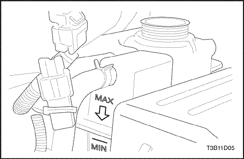
- Fill the surge tank to the specified MAX fill mark on the outside of the tank.
Thermostat - 1.2 DOHC - B12D -
Removal Procedure
Caution : To Prevent personal injury, do not remove the surge tank cap while the engine and the radiator are hot because the heat causes the system to remain under pressure. Scalding fluid and steam may be blown out under pressure.
- Drain the coolant. Refer to "Draining and Refilling the Cooling System"in this section.
- Remove the thermostat housing retaining bolts.
- Remove the thermostat housing.
- Remove the thermostat.
- Inspect the thermostat for proper operation. Refer to “Thermostat Test” in this section.
- Clean the thermostat housing and the cylinder head mating surfaces.
Installation Procedure
- Install the thermostat into the cylinder head recess.
- Install the thermostat housing.
Tighten
Tighten the thermostat housing retaining bolts to 10 N•m (89 lb-in).
- Refill the engine cooling system. Refer to "Draining and Refilling the Cooling System"
in this section.
Thermostat - 1.4 DOHC - G14D -
Removal Procedure
Caution : To prevent personal injury, do not remove the surge tank cap while the engine and the radiator are hot because the heat causes the system to remain under pressure. Scalding fluid and steam may be blown out under pressure.
- Disconnect the negative battery cable.
- Drain the coolant. Refer to "Draining and Refilling the Cooling System"
in this section.
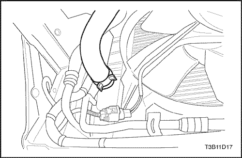
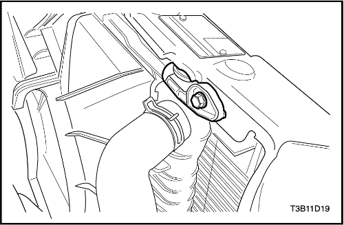
- Remove the upper radiator hose from the thermostat housing.
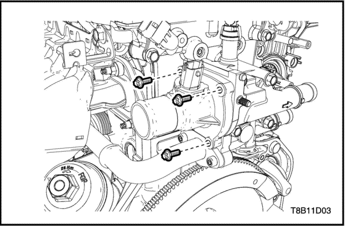
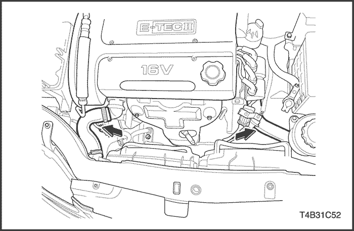
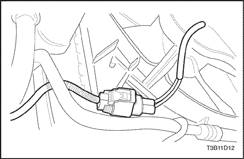
- Disconnect the thermostat wiring harness plug.
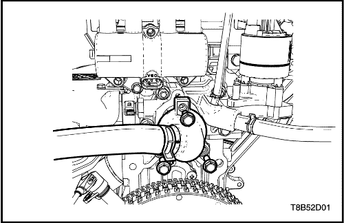
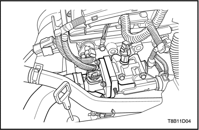
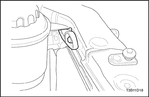
- Remove the thermostat housing retaining bolts.
- Remove the thermostat housing.
- Inspect the thermostat for proper operation. Refer to "Thermostat Test"
in this section.
- Clean the thermostat housing and the cylinder head mating surfaces.
Installation Procedure
Caution :
- Do not use fallen parts. Plastic housing is very brittle and the fallen part may have internal crack that cause coolant leak.
- Do not reuse rubber gaskets.
- Check a coolant leak after the part replacement.
- Fit the thermostat housing to the coolant distributor and use the NEW gasket.
- Install the thermostat housing.
Tighten
Thermostat Housing Retaining Bolt: 8 N•m (5.9 lb-ft).
- Connect the thermostat wiring harness plug.
- Install the upper radiator hose from the thermostat housing.
- Refill the engine cooling system. Refer to "Draining and Refilling the Cooling System"
in this section.
- Connect the negative battery cable.
Water Pump - 1.2 DOHC - B12D -
Removal Procedure
- Drain the coolant. Refer to "Draining and Refilling the Cooling System" in this section.
- Remove the accessory belt. Refer to Section 1C1, DOHC Engine Mechanical.
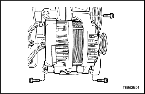
- Remove the generator. Refer to Section 1E, Generator.
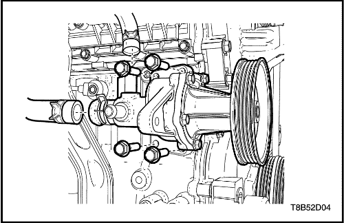
- Remove the water pump retaining nuts, bolts.
- Remove the water pump.
- Remove the ring seal from the water pump.
- Inspect the water pump for cracks, leaks or abnormal noise.
- Cleaning the mating surfaces of the water pump and the cylinder head.
Installation Procedure
- Install a new ring seal to the water pump.
- Install the water pump to the engine block.
Tighten
Tighten the water pump retaining bolts and nuts to 10 N•m (89 lb-in).
- Install the generator. Refer to Section 1E, Generator.
- Install the accessory belt. Refer to Section 1C1, ENGINE MECHANICAL - 1.2L DOHC .
- Refill the engine cooling system. Refer to "Draining and Refilling the Cooling System"
in this section.
Water Pump - 1.4 DOHC - G14D -
Tools Required
EN-48356 Engine Fixture
EN-49201 Water Pump Pulley Remover/Installer
Removal Procedure
- Drain the coolant. Refer to "Draining and Refilling the Cooling System" in this section.
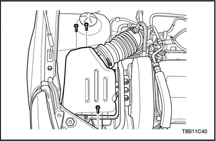
- Remove the air cleaner assembly.
- Remove the RH head lamp assembly. Refer to the Section 9B, Lightening System.
- Disconnect the A/C pipe retainer and let the A/C pipe could be moved.
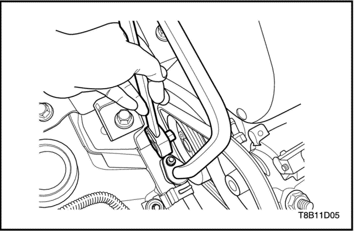
- Remove the water pump pulley retaining bolts using Water Pump Pulley Remover/Installer(EN-49201).
- Remove the accessory belt. Refer to “Accessory Belt”
in this section.
- Fix the engine using Engine Fixture(EN-48356).
- Remove the engine mount.
- Remove the water pump pulley.
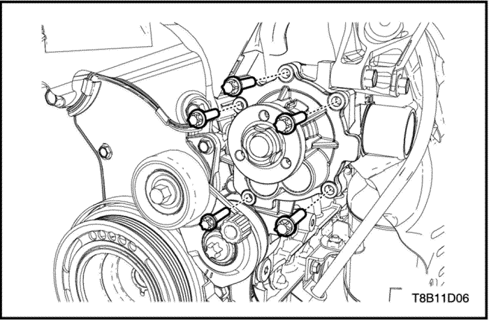
- Remove the water pump retaining bolts.
- Remove the water pump.
- Remove the ring seal from the water pump.
- Inspect the water pump for cracks, leaks or abnormal noise.
- Cleaning the mating surfaces of the water pump and the cylinder head.
Installation Procedure
- Install a new ring seal to the water pump.
- Install the water pump to the engine front cover.
Tighten
Tighten the water pump retaining bolts to 10 N•m (89 lb-in).
- Install the water pump pulley.
- Install the engine mount.
- Install the accessory belt. Refer to “Accessory Belt”
in this section.
- Connect the A/C pipe retainer and fix the A/C pipe.
- Install the RH head lamp assembly. Refer to the Section 9B, Lightening System.
- Install the air cleaner assembly.
- Refill the engine cooling system. Refer to "Draining and Refilling the Cooling System"
in this section.
Electric Cooling Fan
Removal Procedure
- Disconnect the negative battery cable.
- Disconnect the cooling fan electrical connector.
- Disconnect the coolant hose over the cooling fan.
- Remove the electric cooling Fan Mounting bolts.
- Remove the electric cooling Fan.
Installation Procedure
Caution : If a fan blade is bent or damaged in any way, no attempt should be made to repair or reuse the damaged part. A bent or damaged fan assembly must be replaced with a new fan assembly. It is essential that fan assemblies remain in proper balance. A fan assembly that is not in proper balance can fail and fly apart during use, creating extreme danger. Proper balance cannot be assured on a fan assembly that has been bent or damaged.
- Install the electric cooling fan.
- Install the electric cooling Fan Mounting bolts.
Tighten
Tighten the electrical cooling fan moumting bolts to 4 N•m (35 lb-in).
- Connect the coolant hose to the cooling fan.
- Connect the cooling fan electriceal connector
- Connect the negative battery cable.
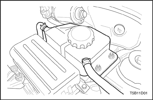
Surge Tank
Removal Procedure
Caution : To prevent personal injury, do not remove the surge tank cap while the engine and the radiator are hot, because the heat causes the system to remain under pressure. Scalding fluid and steam may be blown out under pressure.
- Drain the engine coolant to below the level of the surge tank.
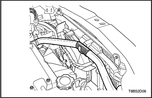
- Loosen the overflow hose clamps and disconnect the overflow hose from the top of the surge tank.
- Disconnect the coolant temperature sensor connector.
- Remove the EGR valve and pipe.
- Remove the tank attaching nuts.
- Remove the tank from the vehicle.
- Clean the inside and the outside of the surge tank and the surge tank cap with soap and water.
- Rinse the surge tank and the cap thoroughly.
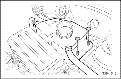
Installation Procedure
- Install the surge tank to the vehicle.
- Secure the surge tank with the attaching nuts.
Tighten
Tighten the surge tank attaching nuts to 20 N•m (178 lb-in).
- Install the EGR valve and pipe.
- Connect the coolant temperature sensor connector.
- Connect the overflow hose to the surge tank.
- Secure the overflow hose to the surge tank with the hose clamps.
- Fill the surge tank with the coolant to the center ridge, or to the MAX mark.
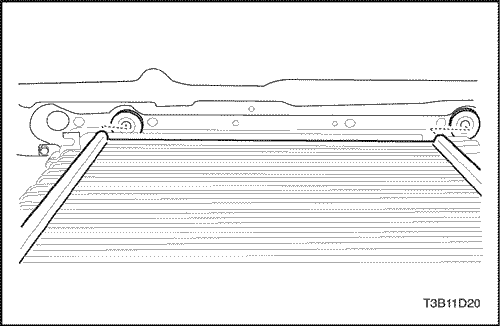
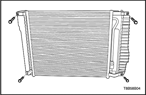
Radiator
Removal Procedure
Caution : To avoid injury, do not remove the radiator while the engine is hot. Scalding fluid and steam may be blown out under pressure.
- Disconnect the negative battery cable.
- Remove the power steering oil tank. Refer to Section 6B, Power Steering Pump.
- Drain the coolant. Refer to "Draining and Refilling the Cooling System"
in this section.
- Remove the electric cooling fans. Refer to "Electric Cooling Fan"
in this section.
- Disconnect the upper cooling fan hose from the radiator.
- Disconnect the lower radiator hose from the radiator.
- Remove the return hose from the surge tank at the radiator.
- Remove the left upper radiator retaining bracket.
- Remove the right upper radiator retaining bracket.
- Remove the A/C gas. Refer to Section 7B, Manual Control Heating, Ventilation and Air Conditioning System.
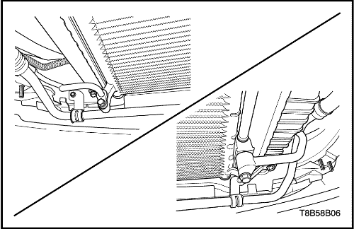
- Remove the high-pressure pipe bolt from the both side of the A/C condensor. Refer to Section 7B, Manual Control Heating, Ventilation and Air Conditioning System.
- Remove up the radiator from the vehicle with the A/C condensor.
- Remove the A/C condensor from the radiator. Refer to Section 7B, Manual Control Heating, Ventilation and Air Conditioning System.
Installation Procedure
- Install the A/C condensor from the radiator. Refer to Section 7B, Manual Control Heating, Ventilation and Air Conditioning System.
- Install the radiator with the A/C condensor.
- Install the high-pressure pipe bolt from the both side of the A/C condensor. Refer to Section 7B, Manual Control Heating, Ventilation and Air Conditioning System.
- Refill the A/C gas. Refer to Section 7B, Manual Control Heating, Ventilation and Air Conditioning System.
- Install the right upper radiator retaining bracket.
Tighten
Upper right radiator retaining bracket bolt : 10 N•m (89 lb-in).
- Install the left upper radiator retaining bracket.
Tighten
Upper left radiator retaining bracket bolt : 10 N•m (89 lb-in).
- Install the return hose from the surge tank at the radiator.
- Connect the lower radiator hose from the radiator.
- Connect the upper cooling fan hose from the radiator.
- Install the electric cooling fans. Refer to ”Electric Cooling Fan”
in this section.
- Refill the engine cooling system. Refer to Section 6B, Power Steering Pump.
- Install the power steering oil tank. Refer to Section 6B, Power Steering Pump.
- Connect the negative battery cable.
GENERAL DESCRIPTION
AND SYSTEM OPERATION
General Description
The cooling system maintains the engine temperature at an efficient level during all engine operating conditions. When the engine is cold, the cooling system cools the engine slowly or not at all. This slow cooling of the engine allows the engine to warm up quickly.
The cooling system includes a radiator and recovery subsystem, cooling fans, a thermostat and housing, a water pump, and a water pump drive belt. The timing belt drives the water pump.
All components must function properly in order for the cooling system to operate. The water pump draws the coolant from the radiator. The coolant then circulates through water jackets in the engine block, the intake manifold, and the cylinder head. When the coolant reaches the operating temperature of the thermostat, the thermostat opens. The coolant then goes back to the radiator where it cools.
This system directs some coolant through the hoses to the heater core. This provides for heating and defrosting. The surge tank is connected to the radiator to recover the coolant displaced by expansion from the high temperatures. The surge tank maintains the correct coolant level
The cooling system for this vehicle has no radiator cap or filler neck. The coolant is added to the cooling system through the surge tank.
Radiator
This vehicle has a lightweight tube-and-fin aluminum radiator. Two models of radiators are available: small, standard, and heavy duty. The two models vary only by capacity. Plastic tanks are mounted on the right and the left sides of the radiator core.
On vehicles equipped with automatic transaxles, the transaxle fluid cooler lines run through the left radiator tank. A radiator drain cock is on this radiator.
To drain the cooling system, open the drain cock.
Surge Tank
The surge tank is a transparent plastic reservoir, similar to the windshield washer reservoir.
The surge tank is connected to the radiator by a hose and to the engine cooling system by another hose. As the vehicle is driven, the engine coolant heats and expands. The portion of the engine coolant displaced by this expansion flows from the radiator and the engine into the surge tank. The air trapped in the radiator and the engine is degassed into the surge tank.
When the engine stops, the engine coolant cools and contracts. The displaced engine coolant is then drawn back into the radiator and the engine. This keeps the radiator filled with coolant to the desired level at all times and increases the cooling efficiency.
Maintain the coolant level between the MIN and the MAX marks on the surge tank when the system is cold.
Water Pump
The belt-driven centrifugal water pump consists of an impeller, a drive shaft, and a belt pulley. The water pump is mounted on the front of the transverse-mounted engine, and is driven by the timing belt.
The impeller is supported by a completely sealed bearing.
The water pump is serviced as an assembly and, therefore, cannot be disassembled.
Thermostat
An electric Controlled-type thermostat controls the flow of the engine coolant through the engine cooling system.
The thermostat stops the flow of the engine coolant from the engine to the radiator to provide faster warm up, and to regulate the coolant temperature. The thermostat remains closed while the engine coolant is cold, preventing circulation of the engine coolant through the radiator. At this point, the engine coolant is allowed to circulate only throughout the heater core to warm it quickly and evenly.
As the engine warms, the thermostat opens. This allows the engine coolant to flow through the radiator where the heat is dissipated through the radiator. This opening and closing of the thermostat permits enough engine coolant to enter the radiator to keep the engine within proper engine temperature operating limits.
The effects and features of ECT(Electric Controlled Thermostat) is that the engine and its cooling system operates at a less than ideal condition ♂ at part-load , such as city driving or slow cruising, leading to higher fuel ♂ consumption and emissions output. And fuel consumption, emissions output, engine performance and cooling performance can be improved by varying the coolant temperature at each driving condition. The advanced coolant temperature control can be achieved by using the ♂ electrically assisted thermostat.
In case of a wax pellet-type thermostat, thermostat valve is moved only by the coolant temperature mechanically. This type is impossible to control the coolant temperature to the particular set point arbitrarily. But Electric Controlled Thermostat valve is moved by the coolant temperature and the electricity signal. The electric thermostat provides a chance to control the coolant temperature to the particular set point arbitrarily .
Electric Cooling Fan
Caution : Keep hands, tools, and clothing away from the engine cooling fans to help prevent personal injury. This fan is electric and can turn ON whether or not the engine is running.
Caution : If a fan blade is bent or damaged in any way, no attempt should be made to repair or reuse the damaged part. A bent or damaged fan assembly should always be replaced with a new one.
The cooling fans are mounted behind the radiator in the engine compartment. The electric cooling fans increase the flow of air across the radiator fins and across the condenser on air conditioned (A/C)-equipped vehicles. This helps to speed cooling when the vehicle is at idle or
moving at low speeds.
The fan size is 366 mm (14.4 inches) (Non-A/C model is 300mm (11.8inches))in diameter with five blades to aid the airflow through the radiator and the condenser. An electric motor attached to the radiator support drives the fan.
A/C Off or Non-A/C Model
- The cooling fan(s) are actuated by the powertrain control module (PCM) in vehicles with an automatic transaxle or the engine control module (ECM) using a low-speed cooling fan relay and a high-speed cooling fan relay. On A/C-equipped vehicles, a series/parallel cooling fan relay is also used.
- The PCM or the ECM will turn the cooling fan(s) on at low speed when the coolant temperature reaches 93°C (199°F) and high speed at 97°C (207°F).
- The PCM or the ECM will change the cooling fan(s) from high speed to low speed at 94°C (201°F) and turn the cooling fans off at 90°C (194°F).
A/C ON
- The PCM or the ECM will turn the cooling fans on at low speed when the A/C system is on. The PCM or the ECM will change to high speed when the coolant temperature reaches 97°C (207°F) or high-side A/C pressure reaches 1 882 kPa (273 psi).
- The cooling fans will return to low speed when the coolant temperature reaches 94°C (201°F) or high-side A/C pressure reaches 1 448 kPa (210 psi).
Engine Coolant Temperature Sensor
The coolant temperature sensor (CTS) uses a thermistor to control the signal voltage to the engine control module (ECM) and controls the instrument panel temperature indicator.
Engine Block Heater
The vehicle is designed to accept an engine block heater. The engine block heater helps to warm the engine for improved cold weather starting. It can also help reduce fuel consumption when a cold engine is warming up.
The engine block heater utilizes an existing expansion plug for installation and is located under the intake manifold.
Contact your GMDAT dealer for further information or installation.