SECTION 2C
FRONT SUSPENSION
SPECIFICATIONS
General Specifications
|
Application
|
Trim Height
|
|
Center of Front Wheel to Bottom of Front Wheel Well
|
344 mm (13.5 in.)
|
|
Center of Rear Wheel to Bottom of Rear Wheel Well
|
343 mm (13.5 in.)
|
Fastener Tightening Specifications
|
Application
|
N•m
|
Lb-Ft
|
Lb-In
|
|
Ball Joint-to-Control Arm Nuts
|
150
|
111
|
1328
|
|
Ball Joint-to-Knuckle/Strut Nut
|
55
|
41
|
487
|
|
Control Arm Front Mounting Bolts
|
110
|
81
|
972
|
|
Drive Axle-to-Hub Caulking Nut
|
300
|
221
|
2655
|
|
Piston Rod Nut
|
60
|
44
|
531
|
|
Stabilizer Shaft-to-Iink nut
|
50
|
37
|
-
|
|
Strut Assembly-to-Body Nuts
|
60
|
44
|
531
|
|
Strut Cartridge Closure Nut
|
200
|
148
|
1776
|
|
Impact Pipe-to-Front Crossmember/Radiator Lower Support Bolts
|
100
|
74
|
885
|
|
Crossmember Support Bracket-to-Crossmember Bolts
|
50
|
37
|
443
|
SPECIAL TOOLS
Special Tools Table
 
|
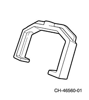
CH-46560-01
Bridge
|
|
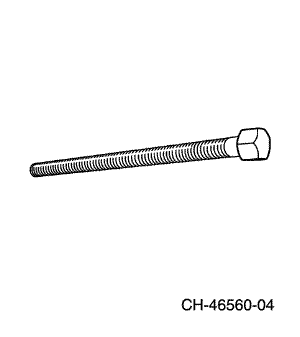
CH-46560-04
Threaded Rod
|
|
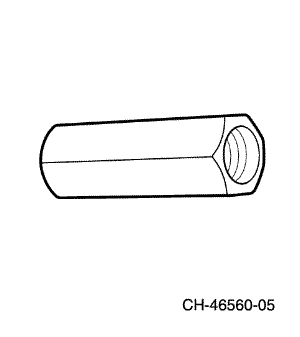
CH-46560-05
Nut
|
|
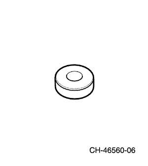
CH-46560-06
Bearing
|
|
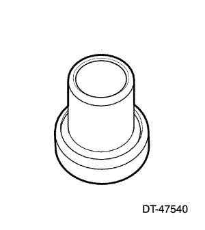
DT-47540
Wheel Hub Spacer
|
|
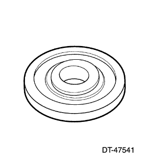
DT-47541
Wheel Bearing Spacer
|
|
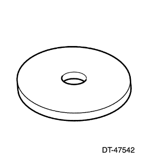
DT-47542
Wheel Bearing Spacer
|
|
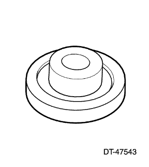
DT-47543
Wheel Bearing Spacer
|
|
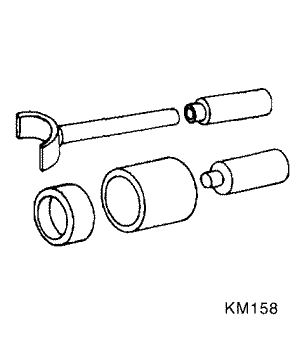
KM-158
Remover/Installer
|
|
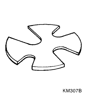
KM-307-B
Removal Plate
|
|
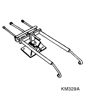
KM-329-A
Spring Compressor
|
|
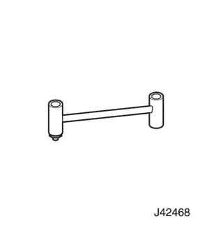
J-42468
Front Strut Mount Nut Wrench
|
|
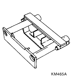
KM-465-A
Front Spring Compressor
|
|
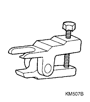
KM-507-B
Ball Joint Remover
|
|
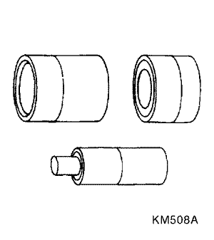
KM-508-A
Remover/Installer
|
|
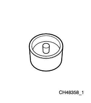
CH48358_1
Front Control Arm Rear Bushing Remover
|
|
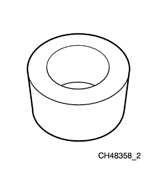
CH48358_2
Front Control Arm Rear Bushing Remover
|
|
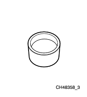
CH48358_3
Front Control Arm Rear Bushing Installer
|
|
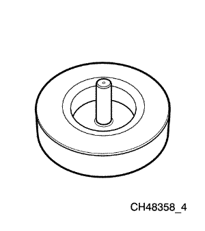
CH48358_4
Front Control Arm Rear Bushing Installer
|
DIAGNOSIS
Strut Dampener
A strut dampener is basically a shock absorber. However, strut dampeners are easier to extend and retract by hand than are shock absorbers. Strut dampeners are used only on the front in most vehicles, including this vehicle. Shock absorbers are used on the rear wheels.
Struts Seem Weak
|
Checks
|
Action
|
|
Check the tire pressures.
|
Adjust the tire pressures to the specifications on the
tire placard.
|
|
Check the load conditions under which the vehicle is
normally driven.
|
Consult with the owner to confirm the owner’s
understanding of normal load conditions.
|
|
Check the compression and rebound effectiveness of
the strut dampener.
|
Quickly push down and then lift up on the corner of
the bumper nearest the strut dampener being tested.
Compare the compression and rebound with those of
a similar vehicle that has an acceptable ride quality.
Replace the strut dampener, if needed.
|
Struts Are Noisy
|
Checks
|
Action
|
|
Check the mountings for looseness or damage.
|
Tighten the strut dampener. Replace the strut
dampener, if needed.
|
|
Check the compression and rebound effectiveness of
the strut dampener.
|
Quickly push down and then lift up on the corner of
the bumper nearest the strut dampener being tested.
Compare the compression and rebound with those of
a similar vehicle that has an acceptable ride quality.
Replace the strut dampener, if needed.
|
Leaks
|
Checks
|
Action
|
|
Check for a slight trace of fluid.
|
The strut dampener is OK.
|
|
Check the seal cover on the fully extended strut.
|
Replace the strut dampener.
|
|
Check for an excessive amount of fluid on the strut
dampener.
|
Replace the strut dampener.
|
Ball Joint and Knuckle
Ball Joint Inspection
- Raise the front of the vehicle to allow the front suspension
to hang free.
- Grasp the tire at the top and the bottom.
- Move the top of the tire in an in-and-out motion.
- Look for any horizontal movement of the knuckle relative
to the control arm.
- Ball joints must be replaced under the following conditions:
- The joint is loose.
- The ball seal is cut.
- The ball stud is disconnected from the knuckle.
- The ball stud is loose at the knuckle.
- The ball stud can be twisted in its socket with finger pressure.
Ball Stud Inspection
Make sure to check the tightness of the ball stud in the
knuckle boss during each inspection of the ball joint.
One way to inspect the ball stud for wear is to shake the
wheel and feel for movement of the stud end or the castellated
nut at the knuckle boss.
Another way to inspect the ball stud for wear is to check
the fastener torque at the castellated nut. A loose nut can
indicate a stressed stud or a hole in the knuckle boss.
Worn or damaged ball joints and knuckles must be replaced.
Excessive Friction Check
Use the following procedure to check for excessive friction
in the front suspension:
- Enlist the help of another technician to lift up on the
front bumper, raising the vehicle as high as possible.
- Slowly release the bumper, allowing the vehicle to assume
its normal trim height. See
"General Specifications"
in this section.
- Measure the distance from the street level to the center
of the bumper.
- Push down on the bumper, release slowly, and allow
the vehicle to assume its normal trim height.
- Measure the distance from the street level to the center
of the bumper.
- The difference between the two measurements
should be less than 12.7 mm (0.5 inch). If the difference
exceeds this limit, inspect the control arms, the
struts, and the ball joints for damage or wear.
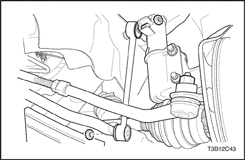
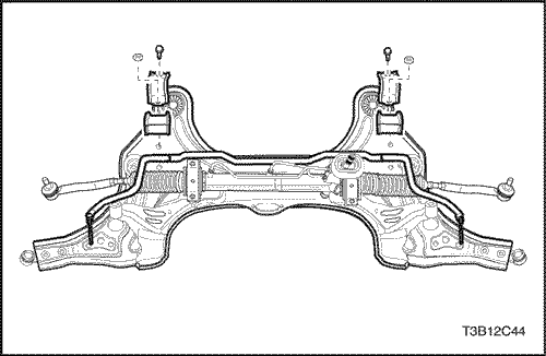
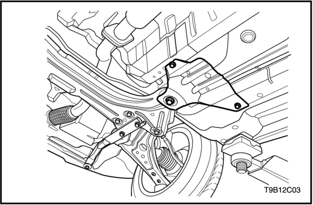
COMPONENT LOCATOR
Front Suspension
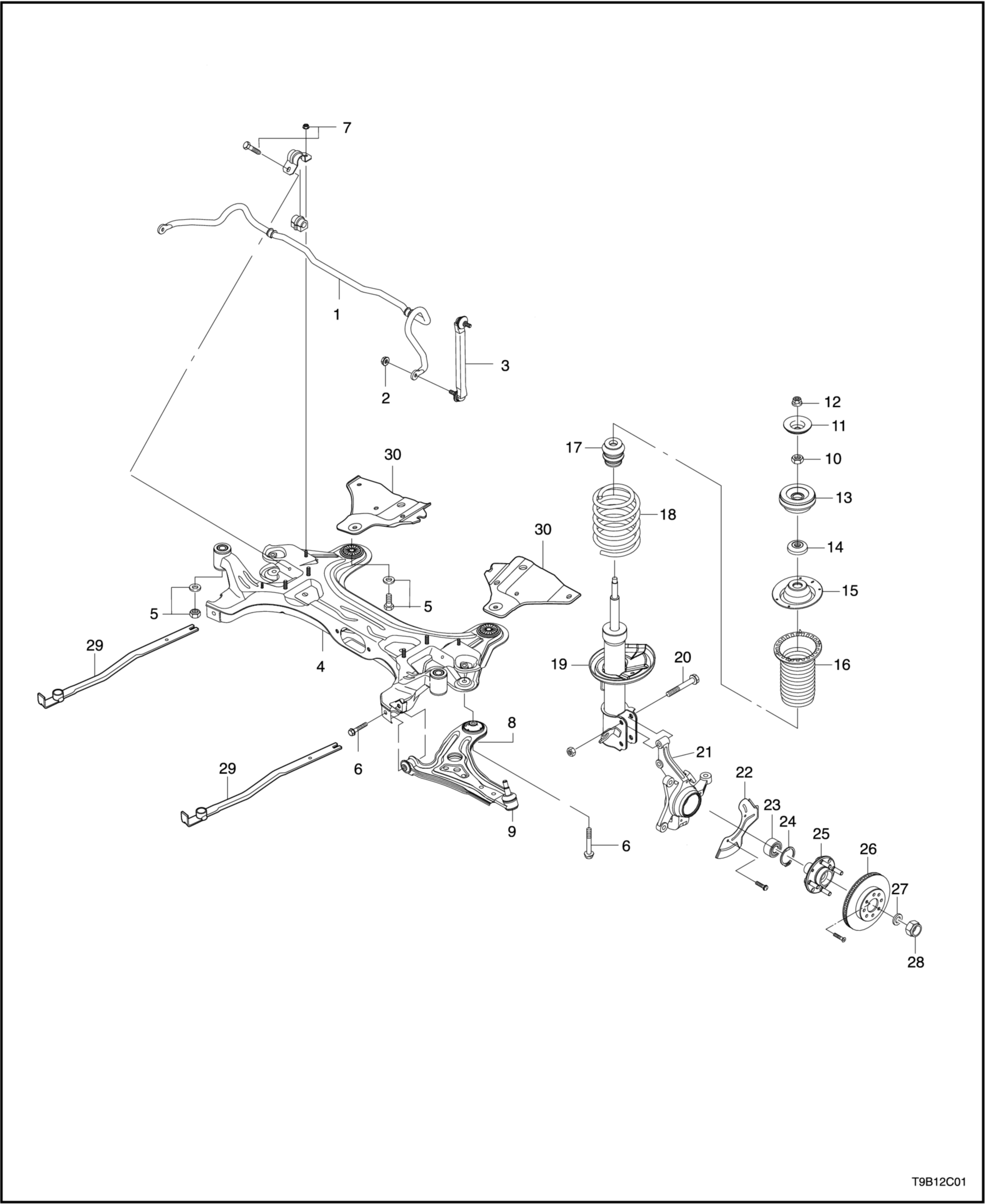
- Stabilizer bar
- Stabilizer link nut
- Stabilizer link
- Crossmember
- Crossmember nut (front direction)
- Control arm connecting bolt
- Stabilizer bar nut
- Control arm
- Ball joint
- Piston rod nut
- Washer
- Strut upper nut
- Strut mount
- Bearing
- Spring upper seat
- Spring upper insulator
- Hallow bumper
- Coil spring
- Thrust
- Thrust bracket bolt
- Steering knuckle
- Cover seat
- Wheel bearing
- Retaining ring
- Wheel hub
- Brake disc
- Washer
- Caulking nut
- Impact Pipe
- Crossmember Support Bracket
MAINTENANCE AND REPAIR
ON-VEHICLE SERVICE

Stabilizer Shaft Link
Removal Procedure
- Lift and suitably support the vehicle, allowing the front
suspension to hang free.
- Remove the front wheel. Refer to Section 2E, Tires
and Wheels.
- Remove the stabilizer shaft-to-knuckle nut and the shaft-to-link nut.
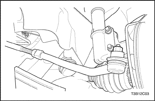
- Disconnect the stabilizer shaft from the knuckle by removing the stabilizer shaft link assembly.
Installation Procedure
- Install the stabilizer shaft into the vehicle.
- Install the stabilizer shaft-to-knuckle nut and the shaft-to-link nut.
Tighten
Tighten the stabilizer shaft link nuts to 50 N•m
(37 lb-ft).
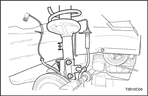
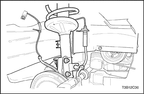
Strut Assembly
Removal Procedure
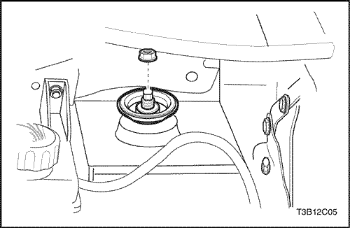
- Remove the cap covering from the strut assembly-to-body nut.
- Loosen the strut assembly -to-body nut that attach the top of the strut assembly
to the vehicle.
- Raise and suitably support the vehicle.
- Support the front lower control arm with a jack stand near the ball joint in order to avoid overextending the CV joints and the brake hose.
- Remove the wheel. Refer to Section 2E, Tires and
Wheels.
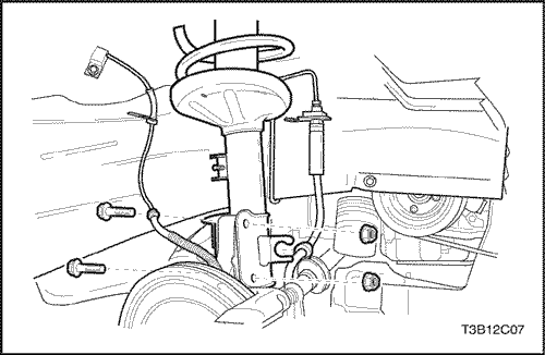
- Remove the speed sensor wire from the strut bracket, if equipped.
- Remove the nuts and bolts from the strut.
- Remove the stabilizer shaft link upper nut.
- Remove the stabilizer shaft upper stud from the strut bracket.
- Remove the strut assembly-to-body nuts.
- Remove the strut assembly from the vehicle.
Installation Procedure
Notice : Chipping or scratching the spring coating when
handling the front suspension coil spring can cause the
spring to fail.
- Install the strut assembly into the vehicle with the strut assembly-to-body nuts.
Tighten
Tighten the strut assembly-to-body nut to 60 N•m
(44 lb-ft).
- Install the strut nut cap.
- Install the nuts and bolts to the strut.
Tighten
Tighten the knuckle-to-strut nuts and bolts to 100 N•m (74 lb-ft).
- Install the stabilizer shaft upper stud to the strut bracket.
- Install the stabilizer shaft link upper nut.
Tighten
Tighten the stabilizer shaft link upper nut to 50 N•m (37 lb-ft).
- Install the brake hose to the strut bracket.
- Install the ABS speed sensor wire to the strut bracket, if equipped.
- Remove the jack stands and lower the vehicle.
Control Arm
Tools Required
KM-507-B Ball Joint Remover
Removal Procedure
- Raise and suitably support the vehicle.
- Place the jackstands under the frame of the vehicle.
- Lower the vehicle slightly so the weight of the vehicle
rests on the jackstands and not on the control arms.
- Remove the wheel. Refer to Section 2E, Tires and
Wheels.
- Disconnect the stabilizer shaft from the control arm
by removing the control armlink bolt assembly.Refer
to
"Stabilizer Shaft and Insulators"
in this section.
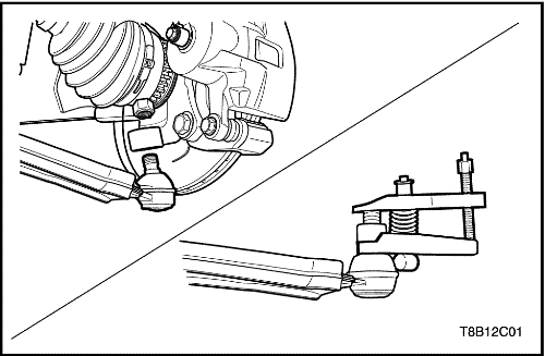
- Remove the retaining clip and the ball joint-to-knuckle/strut nut from the ball joint.
- Disconnect the ball joint from the steering knuckle
using the ball joint remover KM-507-B.
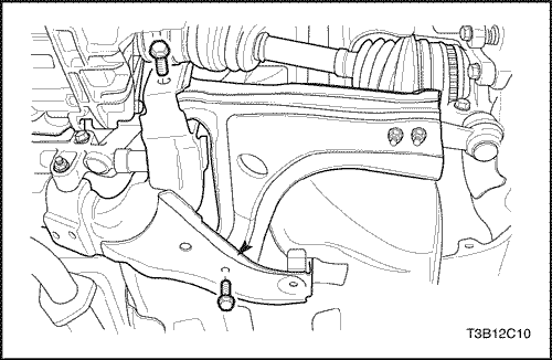
- Remove the control arm front mounting bolt.
- Remove the control arm rear mounting bolts and the
bracket.
- Remove the control arm from the vehicle.
Installation Procedure
- Install the control arm onto the vehicle.
- Connect the front of the control arm to the body of
the vehicle with the front mounting bolt and the
washer.
- Apply a thread sealer to the control arm rear mounting
bolts.
- Connect the rear of the control arm to the body of
the vehicle with the rear mounting bracket and bolts.
Important : Do not tighten the control arm bolts at this
point.
Notice : Use a new self-locking nut to install the control
arm link bolt assembly. Failure to do so will allow the normal
vibration of the vehicle to loosen the nut and damage
the vehicle.
- Install the stabilizer shaft link bolt assembly. Refer to
"Stabilizer Shaft and Insulators"
in this section.
- Connect the ball joint to the steering knuckle.
- Tighten the ball joint-to-knuckle/strut nut.
Tighten
Tighten the ball joint-to-knuckle/strut nut to 55 N•m (41 lb-ft).
- Connect the retaining clip to the ball joint stud.
- Install the wheel. Refer to Section 2E, Tires and
Wheels.
- Raise the vehicle.
- Place the jackstands under the control arms.
- Lower the vehicle.
Important : The control arms must support the weight of
the vehicle while the control arm mounting bolts are being
tightened.
- Tighten the control arm rear mounting bolts.
Tighten
Tighten the control arm rear mounting bolts to 110 N•m
(81lb-ft).
- Tighten the control arm front mounting bolt.
Tighten
Tighten the control arm front mounting bolt to 110 N•m
(81 lb-ft).
- Raise the vehicle.
- Remove the jackstands.
- Lower the vehicle.
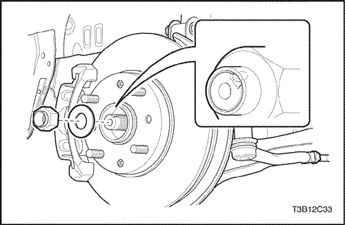
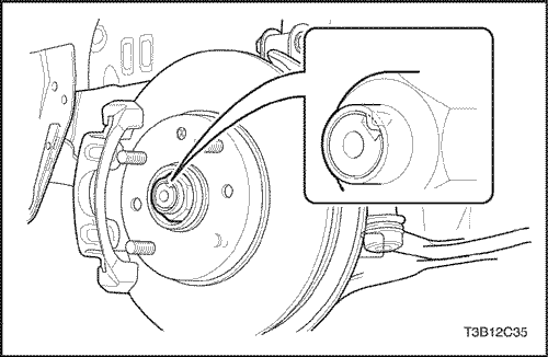
Steering Knuckle
Removal Procedure
- Remove the front wheels.Refer
to Section 2E, Tires and
Wheels.
- Remove the caulking nut.
- Remove the tie rod end from the knuckle.
- Remove the control arm ball joint.
- Remove the brake caliper.
- Remove the brake disk.Refer to Section 4E, Front Disk Brakes.
- Remove the ABS wheel speed sensor, if equipped Refer to Section 4F, ABS.
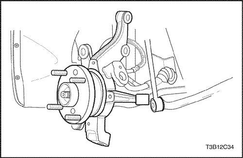
- Remove the backing plate.
- Remove the front strut bolts.
- Remove the knuckle assembly.
Installation Procedure
- Install the knuckle assembly to the front strut with bolt and nuts.
Tighten
Tighten the knuckle assembly to the front strut with bolt and
nuts to 100 N•m
(74lb-ft).
- Install the backing plate with the screws.
Tighten
Tighten the backing plate with the screws to 4 N•m (3lb-ft).
- Install the ABS wheel speed sensor.
- Install the brake disk and caliper.Refer to Section 4D, Front Disk Brakes.
- Install the control arm ball joint.Refer to this Section, Unit Repair
- Install the tie rod end to the knuckle. Refer to this Section.
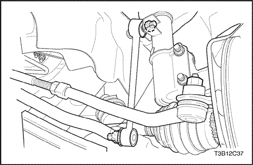
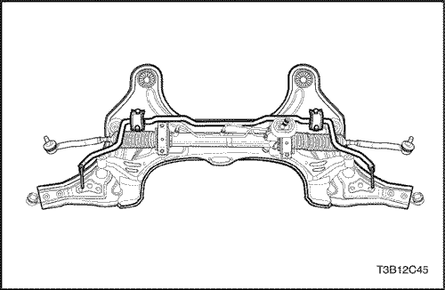
Crossmember Assembly
Removal Procedure
- Remove the front wheels.
- Remove the control arm ball joint and stabilizer shaft link nut (lower). Refer to this Section.
- Remove the tie rod end ball joint. Refer to this Section.
- Remove the engine mounting reaction rod bolts.
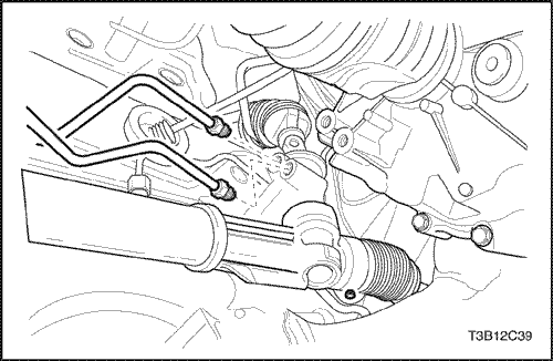
- Drain the power steering fluid.
- Remove the power steering pipe fittings.
- Remove the interm shaft lower joint.
Caution : When the engine is hot, do not remove the above parts from the vehicle otherwise, personal injury can be caused by hot components of the vehicle.
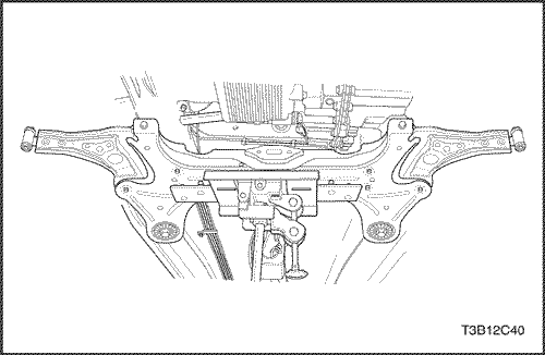
- Remove the crossmember assembly.
Caution : To avoid personal injury or vehicle damage, the crossmember should be supported by jackstand prior to the removal.
- Remove the stabilizer bar, power steering gear set and control arm from the crossmember.
Installation Procedure
- Install the stabilizer bar, power steering gearset and control arm from the crossmember.
- Install the crossmember assembly front to body nut and the crossmember assembly rear to body bolt.
Tighten
Tighten the crossmember assembly front to body nut and
rear to body bolt to 150 N•m
(111 lb-ft).
- Connect the interm shaft lower joint and power steering pipe fittings.
Tighten
Tighten the power steering pipe fittings to 22 N•m
(16 lb-ft).
- Fill the fluid reservoir with the power steering fluid.
- Inspect for leaks. If there are leaks, correct the cause of the leaks and bleed the system. Refer to Section 6A, Bleeding the Power Steering System.
- Install the engine mounting reaction rod bolts.
Tighten
Tighten the engine mounting reaction rod bolts to 60 N•m
(44 lb-ft).
- Install the tie rod end ball joint nut.
Tighten
Tighten the tie rod end ball joint nut to 45 N•m
(33 lb-ft).
- Install the control arm ball joint and stabilizer shaft link nut (lower). Refer to this Section.
Stabilizer Bar
Removal Procedure
- Remove the crossmember assembly. Refer to this Section
- Remove the stabilizer bar from the crossmember assembly by unscrewing the u-clamp bolts.
Installation Procedure
- Install the u-clamp bolts to the stabilizer bar.
Tighten
Tighten the u-clamp bolts to the stabilizer bar to 25 N•m
(18 lb-ft).
- Install the crossmember assembly. Refer to this Section
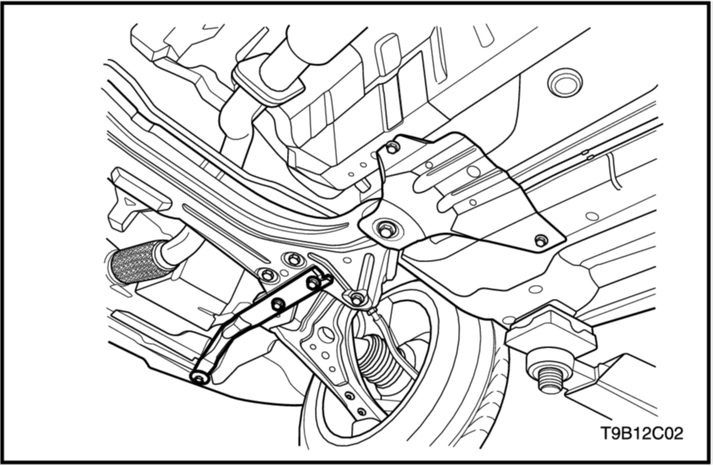
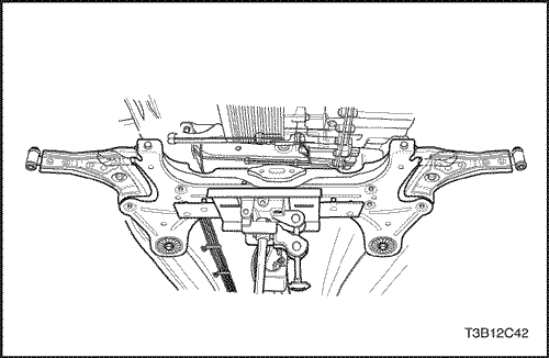
Impact Pipe
Removal Procedure
- Remove the bolts from the impact pipes.
- Remove the impact pipes.
Installation Procedure
- Install the impact pipes by tightening the bolts.
Tighten
Tighten the impact pipes securing bolts to 100 N•m
(74 lb-ft).
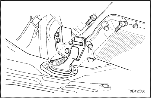
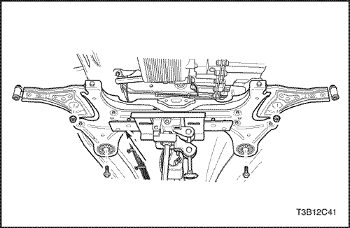
Crossmember Support Bracket
Removal Procedure
- Support the crossmember with jack stand.
- Remove the bolts from the crossmember support bracket.
- Remove the crossmember support bracket.
Installation Procedure
- Install the crossmember support bracket by tightening the bolts.
Tighten
Tighten the crossmember support bracket securing bolts to 50 N•m
(37 lb-ft).
- Remove the jack stand.
UNIT REPAIR
Wheel Hub and Wheel Bearing
Tools Required
CH-46560-01 Bridge
CH-46560-04 Threaded Rod
CH-46560-05 Nut
CH-46560-06 Bearing
DT-47540 Wheel Hub Spacer
DT-47541 Wheel Bearing Spacer
DT-47542 Wheel Bearing Spacer
DT-47543 Wheel Bearing Spacer
Disassembly Procedure
- Raise and suitably support the vehicle.
- Remove the steering knuckle from the vehicle. Refer to this section.
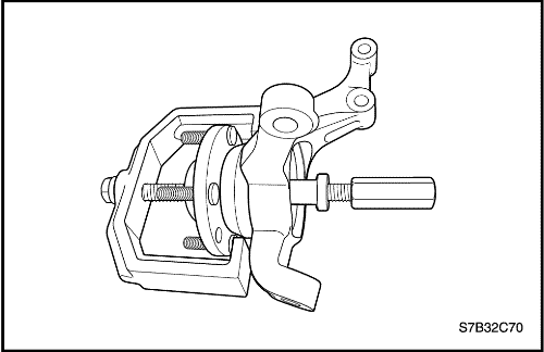
- Insert the threaded rod CH-46560-04 through the bearing CH-46560-06, bridge CH-46560-01 and knuckle assembly.
- Place the Wheel Hub Spacer DT-47540 and nut CH-46560-05 on the rod CH-46560-04.
- Hand-tighten the nuts and remove the wheel hub from the knuckle.
- Remove all the special tools from the knuckle.
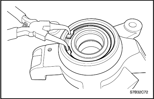
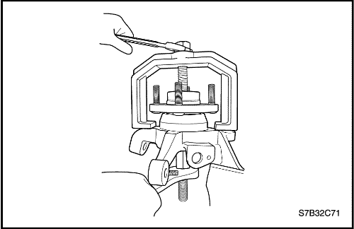
- Remove the retaining ring.
- Insert the threaded rod CH-46560-04 through the bearing CH-46560-06, bridge CH-46560-01 and knuckle assembly.
- Place the Wheel Hub Spacer DT-47541 and nut CH-46560-05 on the rod CH-46560-04.
- Hand-tighten the nuts and remove the wheel bearing from the knuckle.
- Remove all the special tools from the knuckle.
Assembly Procedure
- Insert the threaded rod CH-46560-04 through the bearing CH-46560-06, Wheel Hub Spacer DT-47543, wheel bearing and knuckle.
- Place the Wheel Hub Spacer DT-47542 and nut CH-46560-05 on the rod CH-46560-04.
- Hand-tighten the nuts and install the wheel bearing in the knuckle.
- Remove all the special tools from the knuckle.
- Install the retaining ring.
- Insert the threaded rod CH-46560-04 through the bearing CH-46560-06, Wheel Hub Spacer DT-47540, wheel hub and knuckle.
- Place the Wheel Hub Spacer DT-47542 and nut CH-46560-05 on the rod CH-46560-04.
- Hand-tighten the nuts and install the wheel hub.
- Remove all the special tools from the knuckle assembly.
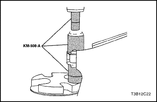
Control Arm Bushings
Tools Required
KM-508-A Remover/Installer
KM-158 Remover/Installer
KM-307-B Removal Plate
Disassembly Procedure
- Remove the control arm. Refer to
"Control Arm"
in
this section.
- Press off the rear bushing using a press, the
remover/installer KM-158, and the removal plate KM-307-B.
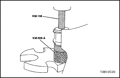
- Press out the front bushing using the remover/installer
KM-508-A, and the remover/installer KM-158.
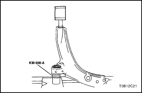
Assembly Procedure
- Coat the control arm rear shaft with a multipurpose
lubricant. Refer to Section 0B, General Information.
- Press the rear bushing onto the shaft. The flat of the
bushing must be on the top side, the same as the ball
joint. Use the remover/installer KM-508-A to support
the control arm.
- Coat the outside of the front bushing and the inside of
the lower control arm with a multipurpose lubricant.
Refer to Section 0B, General Information.
- Press the new bushing into the control arm from the
back to the front, using the remover/installer KM-508-A.
- Center the bushing.
- Install the control arm. Refer to "Control Arm"
in this
section.
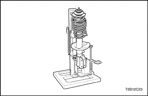
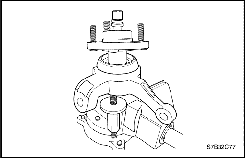
Front Strut Assembly
Tools Required
KM-329-A Spring Compressor or equivalent
J-42468 Front Strut Mount Nut Wrench
Disassembly Procedure
- Remove the strut assembly. Refer to "Strut Assembly"
in this section.
- Fasten the strut assembly to the spring compressor KM-329-A.
Make sure the hooks are seated on the strut spring
properly.
- Compress the front spring with the front spring compressor
KM-329-A.
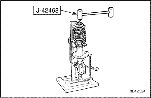
- Use an open end wrench to hold the threaded piston
rod while removing the piston rod nut with J-42468 front strut mount nut wrench.
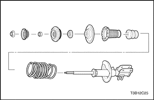
- Remove the strut mount, strut bearing, spring upper seat, spring upper insulator, hallow bumper, coil spring and strut step by step.
Important : Record the position of the front spring seat relative to the strut assembly-to-knuckle bracket. Place the front spring locator back in the same position during assembly.
Assembly Procedure
- Install the lower spring insulator and the spring.
- Compress the spring using the spring compressor KM-329-A.
- Install the strut mount, strut bearing spring upper seat, spring upper insulator, hallow bumper, coil spring and strut step by step.
- Use an open end wrench to hold the threaded piston rod while installing the piston rod nut with J-42468 front strut mount nut wrench.
Tighten
Tighten the piston rod nut to 60 N•m (44 lb-ft).
Important : Locate the coil spring to the original position on the coil spring seat. Check the installation condition of the coil spring.
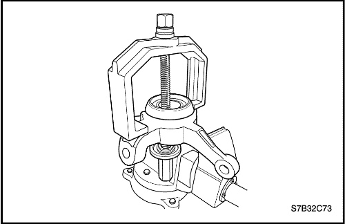
Front Control Arm Bushing (Rear)
Tools Required
CH48358_1 Front Control Arm Bushing Remover
CH48358_2 Front Control Arm Bushing Remover
CH48358_3 Front Control Arm Bushing Installer
CH48358_4 Front Control Arm Bushing Installer
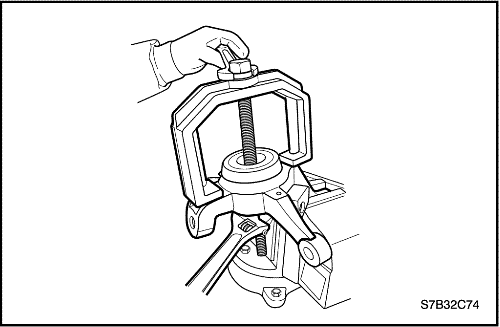
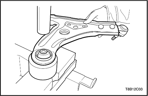
Disassembly Procedure
- Place the control arm assembly on the remover CH48358_2.
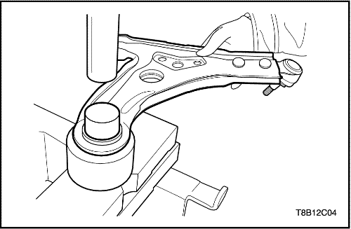
- Place the remover CH48358_1 on the control arm assembly.
- Remove the bushing by pressing the remover CH48358_1 using a press.
- Remove any dirt or burrs from the surface of control arm bushing hole.
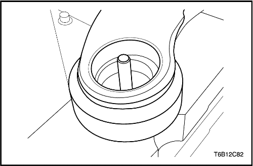
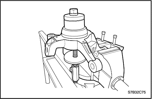
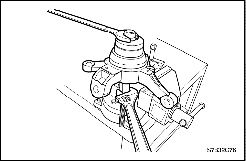
Assembly Procedure
- Place the control arm on the installer CH48358_4.
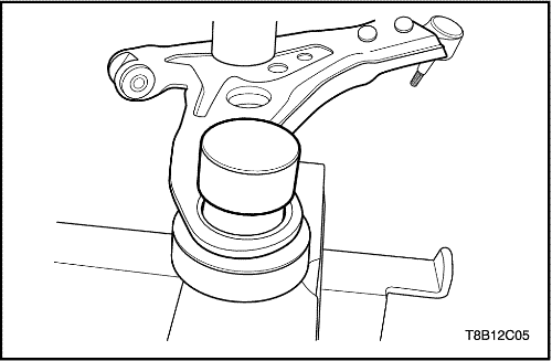
- Place a new bushing and the installer CH48358_3 on the control arm.
- Install the bushing by pressing the installer CH48358_3 using a press.
GENERAL DESCRIPTION AND SYSTEM OPERATION
Front Suspension
The front suspension for this vehicle is a combination
knuckle/strut and spring design.
The control arms pivot from the body. The lower control
arm pivots use rubber bushings. The upper end of the
strut is isolated by a rubber mount and contains a bearing
to allow the wheel to turn.
The lower end of the steering knuckle pivots on a ball
joint bolted to the control arm. The ball joint is fastened
to the steering knuckle with a nut, and to the lower control
arm with rivets.
When servicing the control arm-to-body attachment and
the stabilizer shaft-to-body insulators, make sure the attaching
bolts are loose until the control arms are moved
to the trim height, which is curb height. Trim height is the
normal position to which the control arms move when
the vehicle is sitting on the ground. Refer to
"General
Specifications"
in this section.


