Aveo |
||||||||
|
||||||||
|
Application
|
Unit
|
Description
|
||
|
ABS/EBD
|
Type
|
-
|
4 channel 4 sensor
|
|
|
Source
|
-
|
Continental Teves MK 70
|
||
|
Operation Condition
|
-
|
Wheel lock
Wheel slip
Wheel deceleration
|
||
|
ABS/EBD
|
Turn ON
|
-
|
ABS/EBD inoperative for 3 seconds after ignition switch turned ON
|
|
|
Turn OFF
|
-
|
ABS/EBD operative after 3 seconds when the ignition switch turned ON
|
||
|
Hydraulic Modulater
|
Operation Voltage
|
V
|
10 ~ 16
|
|
|
ABS Main Relay
|
Location
|
-
|
Inside of EBCM
|
|
|
Operation Voltage
|
V
|
9 ~ 16
|
||
|
Front Wheel Speed Sensor
|
Resistance
|
Ω
|
1215 ~1485
|
|
|
Air gap
|
mm
|
1.2
|
||
|
AC voltage
|
V
|
0.205
|
||
|
Rear Wheel Speed Sensor
|
Resistance
|
Ω
|
2295 ~ 2500
|
|
|
Air gap
|
mm
|
1.1
|
||
|
AC voltage
|
V
|
0.205
|
||
|
Speed Ring
|
Front (Rear) Outside Diameter
|
mm
|
83.7 (69)
|
|
|
Front (Rear) inside Diameter
|
mm
|
69.6 (58)
|
||
|
Number of tooth (Front/Rear)
|
EA
|
47/40
|
||
|
Brake Oil
|
Type
|
-
|
DOT-4
|
|
|
Capacity
|
Liter
|
0.5
|
||
|
Application
|
N•m
|
Lb-Ft
|
Lb-In
|
|
ABS Module Mounting Nuts
|
15
|
11
|
-
|
|
Brake Pipe Nuts
|
22
|
16
|
-
|
|
Front Wheel Speed Sensor Bolt
|
8
|
-
|
71
|
 |
Scan Tool
|
|
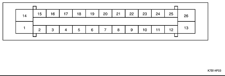
Pin
|
Color
|
Circuit
|
|
1
|
RED/BLK
|
Battery
|
|
2
|
BRN
|
Left Rear Wheel Speed Sensor
|
|
3
|
ORN
|
Left Rear Wheel Speed Sensor
|
|
4
|
-
|
Not Used
|
|
5
|
BRN
|
Right Front Wheel Speed Sensor
|
|
6
|
GRN
|
Right Front Wheel Speed Sensor
|
|
7
|
-
|
Not Used
|
|
8
|
LT BLU
|
Left Front Wheel Speed Sensor
|
|
9
|
YEL
|
Left Front Wheel Speed Sensor
|
|
10
|
LT GRN
|
ABS Warning Lamp Module
|
|
11
|
WHT
|
Right Rear Wheel Speed Sensor
|
|
12
|
BRN
|
Right Rear Wheel Speed Sensor
|
|
13
|
BLK
|
Motor Ground
|
|
14
|
RED
|
Battery
|
|
15
|
-
|
Not Used
|
|
16
|
LT BLU
|
Brake Lamp Switch
|
|
17
|
-
|
Not Used
|
|
18
|
BLK/WHT
|
Data Link Connector (DLC)
|
|
19
|
-
|
Not Used
|
|
20
|
PNK
|
Switched Ignition
|
|
21
|
-
|
Not Used
|
|
22
|
-
|
Not Used
|
|
23
|
-
|
Not Used
|
|
24
|
-
|
Not Used
|
|
25
|
-
|
Not Used
|
|
26
|
BLK
|
Instrument Ground
|
| Step | Action | Value(s) | Yes | No |
| 1 |
Is the scan tool receiving data from the electronic brake control module (EBCM) ?
|
-
|
Go to Step 2
|
Go to Step 6
|
| 2 |
Check the display.
Are there any current DTCs displayed?
|
-
|
Refer to the applicable DTC table
|
Go to Step 3
|
| 3 |
Does the indicator light for 4 seconds and then go off?
|
-
|
Go to Step 5
|
Go to Step 4
|
| 4 |
Check the ABS indicator.
Did the ABS indicator turn on and stay on?
|
-
|
||
| 5 |
Does the indicator light for 4 seconds and then go off?
|
-
|
Go to Step 12
|
|
| 6 |
Is the voltage within the specified value on each terminal?
|
10-16 v
|
Go to Step 7
|
|
| 7 |
Is the resistance equal to the specified value?
|
0 Ω
|
Go to Step 9
|
Go to Step 8
|
| 8 |
Repair the open in the circuit between the terminal 13 (or 26) and the ground G102.
Is the repair complete?
|
-
|
System OK
|
-
|
| 9 |
Use a DVM to measure the resistance between terminal 18 of the ABS wiring harness connector and terminal 7 of the Data Link Connector (DLC). Is the resistance below the specified value?
|
< 2 Ω
|
Go to Step 10
|
Go to Step 11
|
| 10 |
Replace the EBCM unit assembly.
Is the repair complete?
|
-
|
System OK
|
-
|
| 11 |
Repair the open or high resistance in the circuit between terminal 18 of the EBCM harness connector and terminal 7 of the DLC jack.
Is the repair complete?
|
-
|
Go to Step 1
|
-
|
| 12 |
Perform the road test described above.
Are any DTCs set?
|
-
|
Go to the table for the DTC
|
System OK
|
| Step | Action | Value(s) | Yes | No |
| 1 |
Install the scan tool and check for any DTCs.
Is any DTC set?
|
-
|
Go to the chart for the DTC
|
Go to Step 2
|
| 2 |
Does the lamp illuminate for about 4 seconds, then turn off?
|
-
|
Go to Step 3
|
|
| 3 |
With the ignition still ON, observe the oil pressure lamp.
Is the oil pressure lamp illuminated?
|
-
|
Go to Step 4
|
Go to Step 19
|
| 4 |
Does the ABS indicator illuminate?
|
-
|
Go to Step 5
|
Go to Step 8
|
| 5 |
Is there a poor connection at any of these terminals?
|
-
|
Go to Step 6
|
Go to Step 7
|
| 6 |
Repair the faulty terminals or replace the EBCM as required.
Is the repair complete?
|
-
|
System OK
|
-
|
| 7 |
Replace the EBCM.
Is the repair complete?
|
-
|
System OK
|
-
|
| 8 |
Does the resistance match the specified value?
|
0 Ω
|
Go to Step 10
|
Go to Step 9
|
| 9 |
Repair the open or high resistance in the circuit from EBCM connector, terminal 26 to ground G102.
Is the repair complete?
|
-
|
System OK
|
-
|
| 10 |
Is the bulb burned out?
|
-
|
Go to Step 11
|
Go to Step 12
|
| 11 |
Is the repair complete?
|
-
|
System OK
|
-
|
| 12 |
Check the continuity at the I/P cluster connector terminal A2.
Does the ohmmeter show the specified value?
|
≈ 0 Ω
|
Go to Step 14
|
Go to Step 13
|
| 13 |
Repair the contact at the I/P cluster connector terminal A2.
Is the repair complete?
|
-
|
System OK
|
-
|
| 14 |
Check the wiring harnesses and the connectors in the circuit from the I/P cluster terminal A2 to terminal 10 of the EBCM connector.
Does the ohmmeter show the specified value?
|
≈ 0 Ω
|
Go to Step 15
|
Go to Step 16
|
| 15 |
Repair the open or high resistance found.
Is the repair complete?
|
-
|
System OK
|
-
|
| 16 |
Check for continuity between terminal 26 of the EBCM connector and ground G102.
Does the ground connection match the specified value?
|
≈ 0 Ω
|
Go to Step 17
|
Go to Step 18
|
| 17 |
Replace the EBCM.
Is the repair complete?
|
-
|
System OK
|
-
|
| 18 |
Repair the continuity problem between terminal 26 of the ABS wiring harness connector and ground G102.
Is the repair complete?
|
-
|
System OK
|
-
|
| 19 |
Is this fuse blown?
|
-
|
Go to Step 20
|
Go to Step 21
|
| 20 |
Replace fuse F3.
Is the repair complete?
|
-
|
System OK
|
-
|
| 21 |
Check fuse Ef5 in the engine fuse block.
Is this fuse blown?
|
-
|
Go to Step 22
|
Go to Step 23
|
| 22 |
Replace fuse Ef5.
Is the repair complete?
|
-
|
System OK
|
-
|
| 23 |
Measure the voltage at terminal 2 of the ignition switch connector by backprobing.
Does the voltage match the specified value?
|
10-16 v
|
Go to Step 25
|
Go to Step 24
|
| 24 |
Is the repair complete?
|
-
|
System OK
|
-
|
| 25 |
Does the voltage match the specified value?
|
10-16 v
|
Go to Step 27
|
Go to Step 26
|
| 26 |
Replace the ignition switch.
Is the repair complete?
|
-
|
System OK
|
-
|
| 27 |
Does the ohmmeter show the specified value?
|
∞
|
Go to Step 28
|
Go to Step 29
|
| 28 |
Repair the open or the high resistance.
Is the repair complete?
|
-
|
System OK
|
-
|
| 29 |
Is the repair complete?
|
-
|
System OK
|
-
|
| Step | Action | Value(s) | Yes | No |
| 1 |
Check the voltage at the battery.
Is the voltage within the specified value?
|
10-16 v
|
Go to Step 3
|
Go to Step 2
|
| 2 |
Charge or replace the battery as required.
Is the repair complete?
|
-
|
System OK
|
-
|
| 3 |
Check fuse Ef5 in the engine fuse block.
Is the fuse blown?
|
-
|
Go to Step 4
|
Go to Step 8
|
| 4 |
Does the fuse blow again?
|
-
|
Go to Step 6
|
Go to Step 5
|
| 5 |
Check the ABS function.
Is the repair complete?
|
-
|
System OK
|
-
|
| 6 |
Does the ohmmeter show the specified value?
|
0 Ω
|
Go to Step 7
|
Go to Step 25
|
| 7 |
Repair the short to ground in the circuit between terminal 1 of engine fuse block connector C104 and the EBCM connector.
Is the repair complete?
|
-
|
System OK
|
-
|
| 8 |
Check fuse Ef5 in the engine fuse block.
Is the fuse blown?
|
-
|
Go to Step 9
|
Go to Step 13
|
| 9 |
Does the fuse blow again?
|
-
|
Go to Step 11
|
Go to Step 10
|
| 10 |
Check the ABS function.
Is the repair complete?
|
-
|
System OK
|
-
|
| 11 |
Does the ohmmeter show the specified value?
|
0 Ω
|
Go to Step 12
|
Go to Step 25
|
| 12 |
Is the repair complete?
|
-
|
System OK
|
-
|
| 13 |
Check fuse F6 in the I/P fuse block.
Is the fuse blown?
|
-
|
Go to Step 14
|
Go to Step 18
|
| 14 |
Does the fuse blow again?
|
-
|
Go to Step 16
|
Go to Step 15
|
| 15 |
Check the ABS function.
Is the repair complete?
|
-
|
System OK
|
-
|
| 16 |
Does the ohmmeter show the specified value?
|
0 Ω
|
Go to Step 17
|
Go to Step 25
|
| 17 |
Repair the short to ground in the circuit fuse F6 of the I/P fuse block and terminal 20 of the EBCM wiring harness connector.
Is the repair complete?
|
-
|
System OK
|
-
|
| 18 |
Is the voltage within the specified value?
|
10-16 v
|
Go to Step 20
|
Go to Step 19
|
| 19 |
Is the repair complete?
|
-
|
System OK
|
-
|
| 20 |
Check the voltage between ground and terminal 20 of the EBCM connector.
Is the voltage within the specified value?
|
10-16 v
|
Go to Step 22
|
Go to Step 21
|
| 21 |
Is the repair complete?
|
-
|
System OK
|
-
|
| 22 |
Does the ohmmeter show the specified value?
|
0 Ω
|
Go to Step 23
|
Go to Step 26
|
| 23 |
Examine terminals 20, 26, 14, 1, and 13 of the EBCM connector.
Is there a defective terminal?
|
-
|
Go to Step 24
|
Go to Step 25
|
| 24 |
Repair the defective terminal or replace the connector or wiring harness as required.
Is the repair complete?
|
-
|
System OK
|
-
|
| 25 |
Replace the EBCM.
Is the repair complete?
|
-
|
System OK
|
-
|
| 26 |
Repair the defective ground connection.
Is the repair complete?
|
-
|
System OK
|
-
|
| Step | Action | Value(s) | Yes | No |
| 1 |
Check the ABS wiring harness connector.
Is it connected properly?
|
-
|
Go to Step 3
|
Go to Step 2
|
| 2 |
Connect the ABS wiring harness connector.
Is the repair complete?
|
-
|
System OK
|
-
|
| 3 |
Does the ABS indicator lamp go out?
|
-
|
Go to Step 4
|
Go to Step 5
|
| 4 |
Replace the EBCM.
Is the repair complete?
|
-
|
System OK
|
-
|
| 5 |
Does the ABS indicator lamp illuminate?
|
-
|
Go to Step 7
|
Go to Step 6
|
| 6 |
Repair the short to ground in the circuit between connector C207 and the EBCM connector.
Is the repair complete?
|
-
|
System OK
|
-
|
| 7 |
Repair the short to ground in the circuit between I/P cluster connector A2 and connector C207.
Is the repair complete?
|
-
|
System OK
|
-
|
| © Copyright Chevrolet Europe. All rights reserved |


