Aveo |
||||||||
|
||||||||
| Step | Action | Value(s) | Yes | No |
| 1 |
Examine the wheel speed sensor.
Are there any signs of physical damage?
|
-
|
Go to Step 3
|
Go to Step 2
|
| 2 |
Is the resistance within the specified value at approximately 25°C (77°F)?
|
1215-1485 Ω
|
Go to Step 4
|
Go to Step 3
|
| 3 |
Replace the wheel speed sensor.
Is the repair complete?
|
-
|
System OK
|
-
|
| 4 |
Is the output within the specified value?
|
≈ 0.2 v
|
Go to Step 6
|
Go to Step 5
|
| 5 |
Replace the speed sensor or the toothed wheel as required.
Is the repair complete?
|
-
|
System OK
|
-
|
| 6 |
Is the voltage for either of these terminals within the specified value?
|
> 1 v
|
Go to Step 7
|
Go to Step 8
|
| 7 |
Repair the short to voltage in the affected circuit.
Is the repair complete?
|
-
|
System OK
|
-
|
| 8 |
Is the resistance at either circuit less than the specified value?
|
∞
|
Go to Step 9
|
Go to Step 10
|
| 9 |
Repair the short to ground in the affected circuit.
Is the repair complete?
|
-
|
System OK
|
-
|
| 10 |
Is the resistance on either circuit within the specified value?
|
0 Ω
|
Go to Step 12
|
Go to Step 11
|
| 11 |
Repair the open or high resistance in the affected circuit as required.
Clear the DTC by scan tool.
Test the vehicle.
Does the DTC set again?
|
-
|
Go to Step 1
|
System OK
|
| 12 |
Replace the EBCM.
Clear the DTC by scan tool.
Test the vehicle.
Does the DTC set again?
|
-
|
Go to Step 1
|
System OK
|
| Step | Action | Value(s) | Yes | No |
| 1 |
Examine the wheel speed sensor, toothed ring.
Are there any signs of physical damage?
|
-
|
Go to Step 3
|
Go to Step 2
|
| 2 |
Is the resistance within the specified value at approximately 25°C (77°F)?
|
1215-1485 Ω
|
Go to Step 4
|
Go to Step 3
|
| 3 |
Replace the wheel speed sensor.
Is the repair complete?
|
-
|
System OK
|
-
|
| 4 |
Is the output within the specified value?
|
≈ 0.2 v
|
Go to Step 6
|
Go to Step 5
|
| 5 |
Replace the speed sensor or the toothed wheel as required.
Is the repair complete?
|
-
|
System OK
|
-
|
| 6 |
Is the voltage for either of these terminals within the specified value?
|
> 1 v
|
Go to Step 7
|
Go to Step 8
|
| 7 |
Repair the short to voltage in the affected circuit.
Is the repair complete?
|
-
|
System OK
|
-
|
| 8 |
Is the resistance at either circuit less than the specified value?
|
∞
|
Go to Step 9
|
Go to Step 10
|
| 9 |
Repair the short to ground in the affected circuit.
Is the repair complete?
|
-
|
System OK
|
-
|
| 10 |
Is the resistance on either circuit within the specified value?
|
0 Ω
|
Go to Step 12
|
Go to Step 11
|
| 11 |
Repair the open or high resistance in the affected circuit as required.
Clear the DTC by scan tool.
Test the vehicle.
Does the DTC set again?
|
-
|
Go to Step 1
|
System OK
|
| 12 |
Replace the EBCM.
Clear the DTC by scan tool.
Test the vehicle.
Does the DTC set again?
|
-
|
Go to Step 1
|
System OK
|
| Step | Action | Value(s) | Yes | No |
| 1 |
Examine the wheel speed sensor.
Are there any signs of physical damage?
|
-
|
Go to Step 3
|
Go to Step 2
|
| 2 |
Is the resistance within the specified value at approximately 25°C (77°F)?
|
2295-2500 Ω
|
Go to Step 4
|
Go to Step 3
|
| 3 |
Replace the wheel speed sensor.
Is the repair complete?
|
-
|
System OK
|
-
|
| 4 |
Is the output within the specified value?
|
≈ 0.2 v
|
Go to Step 6
|
Go to Step 5
|
| 5 |
Replace the speed sensor or the toothed wheel as required.
Is the repair complete?
|
-
|
System OK
|
-
|
| 6 |
Is the voltage for either of these terminals within the specified value?
|
> 1 v
|
Go to Step 7
|
Go to Step 8
|
| 7 |
Repair the short to voltage in the affected circuit.
Is the repair complete?
|
-
|
System OK
|
-
|
| 8 |
Is the resistance at either circuit less than the specified value?
|
∞
|
Go to Step 9
|
Go to Step 10
|
| 9 |
Repair the short to ground in the affected circuit.
Is the repair complete?
|
-
|
System OK
|
-
|
| 10 |
Is the resistance on either circuit within the specified value?
|
0 Ω
|
Go to Step 12
|
Go to Step 11
|
| 11 |
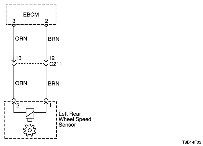
Repair the open or the high resistance in the affected circuit as required. Be sure to check terminal 13 and 12 of connector C211.
Clear the DTC by scan tool.
Test the vehicle.
Does the DTC set again?
|
-
|
Go to Step 1
|
System OK
|
| 12 |
Replace the EBCM.
Clear the DTC by scan tool.
Test the vehicle.
Does the DTC set again?
|
-
|
Go to Step 1
|
System OK
|
| Step | Action | Value(s) | Yes | No |
| 1 |
Examine the wheel speed sensor, toothed ring.
Are there any signs of physical damage?
|
-
|
Go to Step 3
|
Go to Step 2
|
| 2 |
Is the resistance within the specified value at approximately 25°C (77°F)?
|
2295-2500 Ω
|
Go to Step 4
|
Go to Step 3
|
| 3 |
Replace the wheel speed sensor.
Is the repair complete?
|
-
|
System OK
|
-
|
| 4 |
Is the output within the specified value?
|
≈ 0.2 v
|
Go to Step 6
|
Go to Step 5
|
| 5 |
Replace the speed sensor or the toothed wheel as required.
Is the repair complete?
|
-
|
System OK
|
-
|
| 6 |
Is the voltage for either of these terminals within the specified value?
|
> 1 v
|
Go to Step 7
|
Go to Step 8
|
| 7 |
Repair the short to voltage in the affected circuit.
Is the repair complete?
|
-
|
System OK
|
-
|
| 8 |
Is the resistance at either circuit less than the specified value?
|
∞
|
Go to Step 9
|
Go to Step 10
|
| 9 |
Repair the short to ground in the affected circuit.
Is the repair complete?
|
-
|
System OK
|
-
|
| 10 |
Is the resistance on either circuit within the specified value?
|
0 Ω
|
Go to Step 12
|
Go to Step 11
|
| 11 |
Repair the open or the high resistance in the affected circuit as required. Be sure to check terminal 13 and 12 of connector C211.
Clear the DTC by scan tool.
Test the vehicle.
Does the DTC set again?
|
-
|
Go to Step 1
|
System OK
|
| 12 |
Replace the EBCM.
Clear the DTC by scan tool.
Test the vehicle.
Does the DTC set again?
|
-
|
Go to Step 1
|
System OK
|
| Step | Action | Value(s) | Yes | No |
| 1 |
Examine the wheel speed sensor.
Are there any signs of physical damage?
|
-
|
Go to Step 3
|
Go to Step 2
|
| 2 |
Is the resistance within the specified value at approximately 25°C (77°F)?
|
2295-2500 Ω
|
Go to Step 4
|
Go to Step 3
|
| 3 |
Replace the wheel speed sensor.
Is the repair complete?
|
-
|
System OK
|
-
|
| 4 |
Is the output within the specified value?
|
≈ 0.2 v
|
Go to Step 6
|
Go to Step 5
|
| 5 |
Replace the speed sensor or the toothed wheel as required.
Is the repair complete?
|
-
|
System OK
|
-
|
| 6 |
Is the voltage for either of these terminals within the specified value?
|
> 1 v
|
Go to Step 7
|
Go to Step 8
|
| 7 |
Repair the short to voltage in the affected circuit.
Is the repair complete?
|
-
|
System OK
|
-
|
| 8 |
Is the resistance at either circuit less than the specified value?
|
∞
|
Go to Step 9
|
Go to Step 10
|
| 9 |
Repair the short to ground in the affected circuit.
Is the repair complete?
|
-
|
System OK
|
-
|
| 10 |
Is the resistance on either circuit within the specified value?
|
0 Ω
|
Go to Step 12
|
Go to Step 11
|
| 11 |
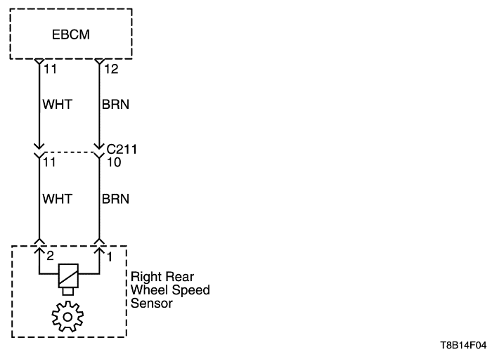
Repair the open or high resistance in the affected circuit as required. Be sure to check terminals 10 and 11 of connector C211.
Clear the DTC by scan tool.
Test the vehicle.
Does the DTC set again?
|
-
|
Go to Step 1
|
System OK
|
| 12 |
Replace the EBCM.
Clear the DTC by scan tool.
Test the vehicle.
Does the DTC set again?
|
-
|
Go to Step 1
|
System OK
|
| Step | Action | Value(s) | Yes | No |
| 1 |
Examine the wheel speed sensor, toothed ring.
Are there any signs of physical damage?
|
-
|
Go to Step 3
|
Go to Step 2
|
| 2 |
Is the resistance within the specified value at approximately 25°C (77°F)?
|
2295-2500 Ω
|
Go to Step 4
|
Go to Step 3
|
| 3 |
Replace the wheel speed sensor.
Is the repair complete?
|
-
|
System OK
|
-
|
| 4 |
Is the output within the specified value?
|
≈ 0.2 v
|
Go to Step 6
|
Go to Step 5
|
| 5 |
Replace the speed sensor or the toothed wheel as required.
Is the repair complete?
|
-
|
System OK
|
-
|
| 6 |
Is the voltage for either of these terminals within the specified value?
|
> 1 v
|
Go to Step 7
|
Go to Step 8
|
| 7 |
Repair the short to voltage in the affected circuit.
Is the repair complete?
|
-
|
System OK
|
-
|
| 8 |
Is the resistance at either circuit less than the specified value?
|
∞
|
Go to Step 9
|
Go to Step 10
|
| 9 |
Repair the short to ground in the affected circuit.
Is the repair complete?
|
-
|
System OK
|
-
|
| 10 |
Is the resistance on either circuit within the specified value?
|
0 Ω
|
Go to Step 12
|
Go to Step 11
|
| 11 |
Repair the open or high resistance in the affected circuit as required. Be sure to check terminals 10 and 11 of connector C211.
Clear the DTC by scan tool.
Test the vehicle.
Does the DTC set again?
|
-
|
Go to Step 1
|
System OK
|
| 12 |
Replace the EBCM.
Clear the DTC by scan tool.
Test the vehicle.
Does the DTC set again?
|
-
|
Go to Step 1
|
System OK
|
| Step | Action | Value(s) | Yes | No |
| 1 |
Can the wheel be rotated?
|
-
|
Go to Step 2
|
Go to Step 6
|
| 2 |
Can the wheel be rotated now?
|
-
|
Go to Step 6
|
Go to Step 3
|
| 3 |
Can the wheel be rotated?
|
-
|
Go to Step 4
|
Go to Step 6
|
| 4 |
Does the DTC set again?
|
-
|
Go to Step 6
|
Go to Step 5
|
| 5 |
Clear the DTC by scan tool.
Test the vehicle.
Does the DTC set again?
|
-
|
Go to Step 1
|
System OK
|
| 6 |
Replace the EBCM.
Clear the DTC by scan tool.
Test the vehicle.
Does the DTC set again?
|
-
|
Go to Step 1
|
System OK
|
| © Copyright Chevrolet Europe. All rights reserved |


