Aveo |
||||||||
|
||||||||
Normal
|
SS1 FAIL
|
||||
Gear
|
SS1
|
SS2
|
Gear
|
SS1
|
SS2
|
|
1 st
|
ON
|
ON
|
3 rd
|
FAIL
|
OFF
|
|
2 nd
|
ON
|
OFF
|
3 rd
|
FAIL
|
OFF
|
|
3 rd
|
OFF
|
OFF
|
3 rd
|
FAIL
|
OFF
|
|
4 th
|
OFF
|
ON
|
4 th
|
FAIL
|
ON
|
| Step | Action | Value(s) | Yes | No |
| 1 |
Is the Hold/Malfunction Indicator Lamp (MIL) ON?
|
-
|
Go to Step 2
|
Inspect the temporary connection failure of the connector and repair it if necessary. Refer to "Wiring Harness and Connector Inspection" in this section.
|
| 2 |
Is DTC P0973 displayed?
|
-
|
Go to Step 3
|
Inspect the temporary connection failure of the connector and repair it if necessary. Refer to "Wiring Harness and Connector Inspection" in this section.
|
| 3 |
Is the measurement within the specified value?
|
20°C (68°F) 11-16 Ω
|
Go to Step 4
|
Go to Step 5
|
| 4 |
Is the inspection OK?
|
-
|
Go to Step 6
|
Replace the vehicle harness or adjustment between the connectors.
|
| 5 |
Is the measurement within the specified value?
|
20°C (68°F) 11-16 Ω
|
Go to Step 7
|
Go to Step 8
|
| 6 |
Clean the connector.
Is the failure resolved?
|
-
|
System OK
|
Go to Step 10
|
| 7 |
Is the condition OK?
|
-
|
Clean the connectors.
|
Replace the vehicle harness or adjustment between the connectors.
|
| 8 |
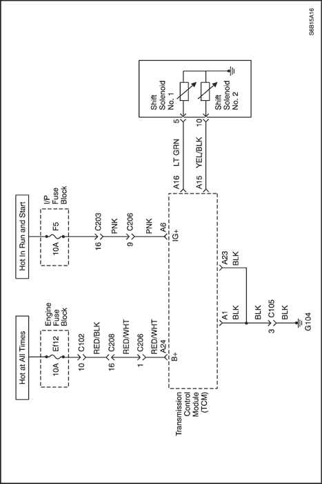
Inspect the SS1. Refer to "Unit Inspection"
in this section.
Is the inspection OK?
|
-
|
Go to Step 9
|
Replace the SS1.
|
| 9 |
Is the condition OK?
|
-
|
Clean the connectors.
|
Replace the T/M wire.
|
| 10 |
Replace the TCM.
Is the replacement completed?
|
-
|
Perform the transmission adaptive learn procedure. Refer to "Transmission Adaptive Learn Procedure" in this section.
|
-
|
Normal
|
SS1 FAIL
|
||||
Gear
|
SS1
|
SS2
|
Gear
|
SS1
|
SS2
|
|
1 st
|
ON
|
ON
|
3 rd
|
FAIL
|
OFF
|
|
2 nd
|
ON
|
OFF
|
3 rd
|
FAIL
|
OFF
|
|
3 rd
|
OFF
|
OFF
|
3 rd
|
FAIL
|
OFF
|
|
4 th
|
OFF
|
ON
|
4 th
|
FAIL
|
ON
|
| Step | Action | Value(s) | Yes | No |
| 1 |
Is the Hold/Malfunction Indicator Lamp (MIL) ON?
|
-
|
Go to Step 2
|
Inspect the temporary connection failure of the connector and repair it if necessary. Refer to "Wiring Harness and Connector Inspection" in this section.
|
| 2 |
Is DTC P0974 displayed?
|
-
|
Go to Step 3
|
Inspect the temporary connection failure of the connector and repair it if necessary. Refer to "Wiring Harness and Connector Inspection" in this section.
|
| 3 |
Is the measurement within the specified value?
|
20°C (68°F) 11-16 Ω
|
Go to Step 4
|
Go to Step 5
|
| 4 |
Is the inspection OK?
|
-
|
Go to Step 6
|
Replace the vehicle harness or adjustment between the connectors.
|
| 5 |
Is the measurement within the specified value?
|
20°C (68°F) 11-16 Ω
|
Go to Step 7
|
Go to Step 8
|
| 6 |
Clean the connector.
Is the failure resolved?
|
-
|
System OK
|
Go to Step 10
|
| 7 |
Is the condition OK?
|
-
|
Clean the connectors.
|
Replace the vehicle harness or adjustment between the connectors.
|
| 8 |
Inspect the SS1. Refer to "Unit Inspection"
in this section.
Is the inspection OK?
|
-
|
Go to Step 9
|
Replace the SS1.
|
| 9 |
Is the condition OK?
|
-
|
Clean the connectors.
|
Replace the T/M wire.
|
| 10 |
Replace the TCM.
Is the replacement completed?
|
-
|
Perform the transmission adaptive learn procedure. Refer to "Transmission Adaptive Learn Procedure" in this section.
|
-
|
Normal
|
SS2 FAIL
|
||||
Gear
|
SS1
|
SS2
|
Gear
|
SS1
|
SS2
|
|
1 st
|
ON
|
ON
|
2 nd
|
ON
|
FAIL
|
|
2 nd
|
ON
|
OFF
|
2 nd
|
ON
|
FAIL
|
|
3 rd
|
OFF
|
OFF
|
3 rd
|
OFF
|
FAIL
|
|
4 th
|
OFF
|
ON
|
3 rd
|
OFF
|
FAIL
|
| Step | Action | Value(s) | Yes | No |
| 1 |
Is the Hold/Malfunction Indicator Lamp (MIL) ON?
|
-
|
Go to Step 2
|
Inspect the temporary connection failure of the connector and repair it if necessary. Refer to "Wiring Harness and Connector Inspection" in this section.
|
| 2 |
Is DTC P0976 displayed?
|
-
|
Go to Step 3
|
Inspect the temporary connection failure of the connector and repair it if necessary. Refer to "Wiring Harness and Connector Inspection" in this section.
|
| 3 |
Is the measurement within the specified value?
|
20°C (68°F) 11-16 Ω
|
Go to Step 4
|
Go to Step 5
|
| 4 |
Is the inspection OK?
|
-
|
Go to Step 6
|
Replace the vehicle harness or adjustment between the connectors.
|
| 5 |
Is the measurement within the specified value?
|
20°C (68°F) 11-16 Ω
|
Go to Step 7
|
Go to Step 8
|
| 6 |
Clean the connector.
Is the failure resolved?
|
-
|
System OK
|
Go to Step 10
|
| 7 |
Is the condition OK?
|
-
|
Clean the connectors.
|
Replace the vehicle harness or adjustment between the connectors.
|
| 8 |
Inspect the SS2. Refer to "Unit Inspection"
in this section.
Is the inspection OK?
|
-
|
Go to Step 9
|
Replace the SS2.
|
| 9 |
Is the condition OK?
|
-
|
Clean the connectors.
|
Replace the T/M wire.
|
| 10 |
Replace the TCM.
Is the replacement completed?
|
-
|
Perform the transmission adaptive learn procedure. Refer to "Transmission Adaptive Learn Procedure" in this section.
|
-
|
Normal
|
SS2 FAIL
|
||||
Gear
|
SS1
|
SS2
|
Gear
|
SS1
|
SS2
|
|
1 st
|
ON
|
ON
|
2 nd
|
ON
|
FAIL
|
|
2 nd
|
ON
|
OFF
|
2 nd
|
ON
|
FAIL
|
|
3 rd
|
OFF
|
OFF
|
3 rd
|
OFF
|
FAIL
|
|
4 th
|
OFF
|
ON
|
3 rd
|
OFF
|
FAIL
|
| Step | Action | Value(s) | Yes | No |
| 1 |
Is the Hold/Malfunction Indicator Lamp (MIL) ON?
|
-
|
Go to Step 2
|
Inspect the temporary connection failure of the connector and repair it if necessary. Refer to "Wiring Harness and Connector Inspection" in this section.
|
| 2 |
Is DTC P0977 displayed?
|
-
|
Go to Step 3
|
Inspect the temporary connection failure of the connector and repair it if necessary. Refer to "Wiring Harness and Connector Inspection" in this section.
|
| 3 |
Is the measurement within the specified value?
|
20°C (68°F) 11-16 Ω
|
Go to Step 4
|
Go to Step 5
|
| 4 |
Is the inspection OK?
|
-
|
Go to Step 6
|
Replace the vehicle harness or adjustment between the connectors.
|
| 5 |
Is the measurement within the specified value?
|
20°C (68°F) 11-16 Ω
|
Go to Step 7
|
Go to Step 8
|
| 6 |
Clean the connector.
Is the failure resolved?
|
-
|
System OK
|
Go to Step 10
|
| 7 |
Is the condition OK?
|
-
|
Clean the connectors.
|
Replace the vehicle harness or adjustment between the connectors.
|
| 8 |
Inspect the SS2. Refer to "Unit Inspection"
in this section.
Is the inspection OK?
|
-
|
Go to Step 9
|
Replace the SS2.
|
| 9 |
Is the condition OK?
|
-
|
Clean the connectors.
|
Replace the T/M wire.
|
| 10 |
Replace the TCM.
Is the replacement completed?
|
-
|
Perform the transmission adaptive learn procedure. Refer to "Transmission Adaptive Learn Procedure" in this section.
|
-
|
| Step | Action | Value(s) | Yes | No |
| 1 |
Is the Hold/Malfunction Indicator Lamp (MIL) ON?
|
-
|
Go to Step 2
|
Inspect the temporary connection failure of the connector and repair it if necessary. Refer to "Wiring Harness and Connector Inspection" in this section.
|
| 2 |
Is DTC P2769 displayed?
|
-
|
Go to Step 3
|
Inspect the temporary connection failure of the connector and repair it if necessary. Refer to "Wiring Harness and Connector Inspection" in this section.
|
| 3 |
Is the measurement within the specified value?
|
20°C (68°F) 11-16 Ω
|
Go to Step 4
|
Go to Step 5
|
| 4 |
Is the inspection OK?
|
-
|
Go to Step 6
|
Replace the vehicle harness or adjustment between the connectors.
|
| 5 |
Is the measurement within the specified value?
|
20°C (68°F) 11-16 Ω
|
Go to Step 7
|
Go to Step 8
|
| 6 |
Clean the connector.
Is the failure resolved?
|
-
|
System OK
|
Go to Step 10
|
| 7 |
Is the condition OK?
|
-
|
Clean the connectors.
|
Replace the vehicle harness or adjustment between the connectors.
|
| 8 |
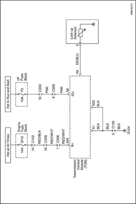
Inspect the lock up solenoid. Refer to "Unit Inspection"
in this section.
Is the inspection OK?
|
-
|
Go to Step 9
|
Replace the lock up solenoid.
|
| 9 |
Is the condition OK?
|
-
|
Clean the connectors.
|
Replace the T/M wire.
|
| 10 |
Replace the TCM.
Is the replacement completed?
|
-
|
Perform the transmission adaptive learn procedure. Refer to "Transmission Adaptive Learn Procedure" in this section.
|
-
|
| Step | Action | Value(s) | Yes | No |
| 1 |
Is the Hold/Malfunction Indicator Lamp (MIL) ON?
|
-
|
Go to Step 2
|
Inspect the temporary connection failure of the connector and repair it if necessary. Refer to "Wiring Harness and Connector Inspection" in this section.
|
| 2 |
Is DTC P2770 displayed?
|
-
|
Go to Step 3
|
Inspect the temporary connection failure of the connector and repair it if necessary. Refer to "Wiring Harness and Connector Inspection" in this section.
|
| 3 |
Is the measurement within the specified value?
|
20°C (68°F) 11-16 Ω
|
Go to Step 4
|
Go to Step 5
|
| 4 |
Is the inspection OK?
|
-
|
Go to Step 6
|
Replace the vehicle harness or adjustment between the connectors.
|
| 5 |
Is the measurement within the specified value?
|
20°C (68°F) 11-16 Ω
|
Go to Step 7
|
Go to Step 8
|
| 6 |
Clean the connector.
Is the failure resolved?
|
-
|
System OK
|
Go to Step 10
|
| 7 |
Is the condition OK?
|
-
|
Clean the connectors.
|
Replace the vehicle harness or adjustment between the connectors.
|
| 8 |
Inspect the lock up solenoid. Refer to "Unit Inspection"
in this section.
Is the inspection OK?
|
-
|
Go to Step 9
|
Replace the lock up solenoid.
|
| 9 |
Is the condition OK?
|
-
|
Clean the connectors.
|
Replace the T/M wire.
|
| 10 |
Replace the TCM.
Is the replacement completed?
|
-
|
Perform the transmission adaptive learn procedure. Refer to "Transmission Adaptive Learn Procedure" in this section.
|
-
|
| © Copyright Chevrolet Europe. All rights reserved |


