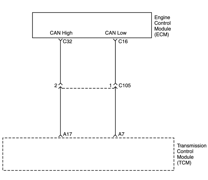


Diagnostic Trouble Code (DTC) U0001
High speed Can Communication
Conditions for Running the DTC
- Engine speed sensor revolution is 400rpm or greater.
- Input speed sensor revolution is 400rpm or greater.
- TCM receives "Bus OFF" state from CAN controller.
Conditions for Setting the DTC
- Above detection cumulatively occurs 7 times.
Action Taken When the DTC Sets
- TCM will request the illumination of MIL and store DTC when TCM detects a failure on the first ignition cycle.
- TCM judges the throttle opening is 0% for shift point and lock-up point control.
- TCM judges the throttle opening is 100% for line pressure control.
- No lock-up
- No self-learning control
- No 4th gear
- TCM judges the engine revolution is 0 rpm.
Conditions for Clearing the DTC
- The TCM turns off the MIL when no further failures detected for three consecutive ignition cycles.
- The scan tool can clear the DTC from the TCM history.
Diagnostic Aids
- This DTC cannot be retrieved with a current status. Diagnosis of a current DTC is accomplished via the symptom, "Scan Tool Does Not Communicate with GMLAN Device".
- An intermittent condition is likely to be caused by a short on the CAN serial data circuits. Use the "Scan Tool Does Not Communicate with GMLAN Device" procedure in order to isolate an intermittent condition.
DTC U0001 - High Speed CAN Communication
| Step |
Action |
Value(s) |
Yes |
No |
| 1 |
Did you perform the Diagnostic System Check?
|
-
|
Go to Step 2
|
|
| 2 |
|
-
|
-
|
-
|
Diagnostic Trouble Code (DTC) U0100
Lost Communication with ECM/PCM
Conditions for Running the DTC
- The failure condition of CAN Bus OFF.
- Engine revolution is 400 rpm or greater.
- Input speed sensor revolution is 400 rpm or greater.
- TCM cannot detect ECM frame for 0.2 seconds continuously.
Conditions for Setting the DTC
- Above detection continuously occurs 10 times.
Action Taken When the DTC Sets
- TCM will request the illumination of MIL and store DTC when TCM detects a failure on the first ignition cycle.
- TCM judges the throttle opening is 0% for shift point and lock-up point control.
- TCM judges the throttle opening is 100% for line pressure control.
- No lock-up
- No self-learning control
- No 4th gear
- TCM judges the engine revolution is 0 rpm.
Conditions for Clearing the DTC
- The TCM turns off the MIL when no further failures detected for three consecutive ignition cycles.
- The scan tool can clear the DTC from the TCM history.
Diagnostic Aids
- A poor connection at the inoperative module may cause this code to set.
- An improperly powered module may cause this code to set.
- If there are multiple non–communicating modules choose the one closest to the data link connector (DLC). Some modules may not have internal protection for specific voltage outputs and may open a battery positive voltage or ignition voltage source fuse. If a voltage input fuse is open and no short is found in that circuit, ensure that no module
output voltage circuit is shorted to ground before replacing the module. This diagnostic can be used for any module that should communicate with CAN serial data providing the vehicle is equipped with the option that uses that module.
DTC U0100 - Lost Communication with ECM/PCM
| Step |
Action |
Value(s) |
Yes |
No |
| 1 |
Did you perform the Diagnostic System Check?
|
-
|
Go to Step 2
|
|
| 2 |
Test the following circuits of the module that is not communicating for an open or a short to ground:
- The battery positive voltage input circuits
- The battery positive voltage output circuits
- The ignition voltage input circuits
- The ignition voltage output circuits
- The switched battery positive voltage circuits
Did you find and correct the condition?
|
-
|
Go to Step 7
|
Go to Step 3
|
| 3 |
- Turn OFF the ignition.
- Test the ground circuits of the module that is not communicating for an open.
Did you find and correct the condition?
|
-
|
Go to Step 7
|
Go to Step 4
|
| 4 |
Test the CAN serial data circuits of the module that is not communicating for an open.
Did you find and correct the condition?
|
-
|
Go to Step 7
|
Go to Step 5
|
| 5 |
Inspect the harness connectors of the module that is not communicating for poor connections and terminal tension at the following circuits:
- The battery positive voltage input circuits
- The battery positive voltage output circuits
- The ignition voltage input circuits
- The ignition voltage output circuits
- The switched battery positive voltage supply circuits
- The ground circuits
- The CAN serial data circuits
Did you find and correct the condition?
|
-
|
Go to Step 7
|
Go to Step 6
|
| 6 |
Replace the module that is not communicating.
Did you complete the replacement?
|
-
|
Go to Step 7
|
-
|
| 7 |
- Clear the DTCs with a scan tool.
- Turn OFF the ignition for 30 seconds.
- Start the engine.
- Operate the vehicle within the Conditions for Setting the DTC. You may also operate the vehicle within the conditions that you observed from the Freeze Frame/Failure Records.
Did the DTC fail this ignition?
|
-
|
Go to Step 2
|
Go to Step 8
|
| 8 |
Check if any additional DTCs are set.
Are there any DTCs that have not been diagnosed?
|
-
|
Go to applicable DTC table
|
System OK
|
Diagnostic Trouble Code (DTC) U0401
Invalid Data Received from ECM/PCM
Conditions for Running the DTC
- Ignition voltage is greater than 9 volts.
- No failure condition of CAN Bus OFF.
- TCM receives engine speed signal for 0.2 seconds continuously.
Conditions for Setting the DTC
- Above detection continuously occurs 10 times.
Action Taken When the DTC Sets
- TCM will request the illumination of hold lamp.
- No lock-up
- No 4th gear
- No self-learning control
- No engine torque reduction control
- No engagement pressure control
- No timing solenoid control for N-D
- TCM judges that engine revolution is 0 rpm.
Conditions for Clearing the DTC
- The TCM turns off the hold lamp when no further failures detected for three consecutive ignition cycles.
- The scan tool can clear the DTC from the TCM history.
- The TCM clears the DTC from the TCM history memory after forty consecutive warm up cycles without fault.
- TCM receives the engine speed signal for 2 seconds.
Cause of Failure
- ECM
- Engine associated parts
DTC U0401 - Invalid Data Received from ECM/PCM
| Step |
Action |
Value(s) |
Yes |
No |
| 1 |
- Turn the ignition OFF.
- Install the Scan tool.
- With the engine OFF, turn the ignition switch to the ON position.
- Select Store Freeze Frame/Failure Records from the Diagnostic Trouble Codes Information menu.
- Store Freeze Frame/Failure Records.
- Select Clear DTC Information from the Diagnostic Trouble Codes Information menu.
- Clear DTC Information.
- Perform one vehicle drive cycle.
Is the Hold/Malfunction Indicator Lamp (MIL) ON?
|
-
|
Go to Step 2
|
|
| 2 |
- Engine running for 10 seconds.
- Ignition ON, engine OFF, verify the DTC U0401 is not set.
Is DTC U0401 set?
|
-
|
Go to Step 3
|
|
| 3 |
Confirm if the DTC U0401 is set along with other DTCs set.
Is the DTC U0401 set along with other DTCs set?
|
-
|
Go to applicable DTC table
|
Go to Step 3
|
| 4 |
Program the ECM.
Is the DTC reset?
|
-
|
Replace the ECM.
|
System OK
|
 |
|
 |
|
| © Copyright Chevrolet Europe. All rights reserved |


