Aveo |
||||||||
|
||||||||

Component
|
Function
|
|
|
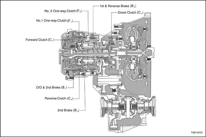
C1
|
Forward Clutch
|
Connects input shaft and front sun gear.
|
|
C2
|
Direct Clutch
|
Connects input shaft and planetary carrier.
|
|
C3
|
Reverse Clutch
|
Connects input shaft and rear sun gear.
|
|
B1
|
O/D & 2nd Brake
|
Prevents rear planetary sun gear from turning either clockwise or counterclockwise.
|
|
B2
|
2nd Brake
|
Prevents outer race of F1 from turning either clockwise or counterclockwise, thus preventing the rear sun gear turning conterclockwise.
|
|
B3
|
1st & Reverse Brake
|
Prevents planetary carrier from turning either clockwise or counterclockwise.
|
|
F1
|
No.1 One-way Clutch
|
When B2 is operating, this clutch prevents rear sun gear from counterclockwise.
|
|
F2
|
No.2 One-way Clutch
|
Prevents planetary carrier from turning counterclockwise.
|
|
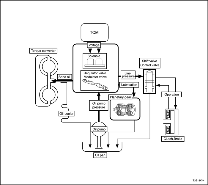
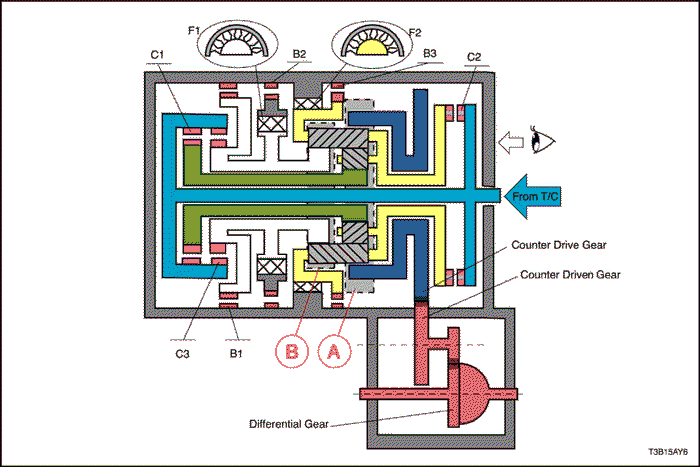
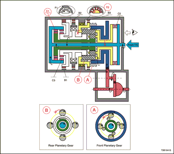
Planetary Gear
|
These gears change the route through which driving froce is transmitted, in accordance with the operation of each clutch and brake, in order to increase or reduce the input and output speed.
|
|
Clutch & Brake
|
Operation
|
|
|
C1
|
Forward Clutch
|
Connects intermediate shaft and front sun gear.
|
|
C2
|
Direct Clutch
|
Connects input shaft and Planetary carrier.
|
|
C3
|
Reverse Clutch
|
Connects intermediate shaft and rear sun gear.
|
|
B1
|
O/D & 2nd Brake
|
Lock rear sun gear
|
|
B2
|
2nd Brake
|
Lock rear sun gear
|
|
B3
|
1st & Reverse Brake
|
Lock Planetary carrier
|
|
F1
|
1way Clutch No.1
|
Lock counterclockwise rotation of rear sun gear, when B2 operations
|
|
F2
|
1way Clutch No.2
|
Lock counterclockwise rotation of planetary carrier
|
Position
|
Solenoid
|
Clutch
|
Brake
|
One-way Clutch
|
||||||||
Shift 1
|
Shift 2
|
Timing
|
C1
|
C2
|
C3
|
B1
|
B2
|
B3
|
F1
|
F2
|
||
| P | ON | ON | OFF | OFF | OFF | OFF | OFF | OFF | OFF | OFF | OFF | |
| R | V<9Km/h | ON | ON | OFF | OFF | OFF | ON | OFF | OFF | ON | OFF | OFF |
| V≥9Km/h | ON | ON | ON | OFF | OFF | OFF | OFF | OFF | OFF | OFF | OFF | |
|
N
|
ON
|
ON
|
OFF
|
OFF
|
OFF
|
OFF
|
OFF
|
OFF
|
OFF
|
OFF
|
OFF
|
|
|
D
|
1st
|
ON
|
ON
|
OFF
|
ON
|
OFF
|
OFF
|
OFF
|
OFF
|
OFF
|
OFF
|
ON
|
|
2nd
|
ON
|
OFF
|
OFF
|
ON
|
OFF
|
OFF
|
OFF
|
ON
|
OFF
|
ON
|
OFF
|
|
|
3rd
|
OFF
|
OFF
|
OFF
|
ON
|
ON
|
OFF
|
OFF
|
ON
|
OFF
|
OFF
|
OFF
|
|
|
(3↔4)
|
OFF
|
ON
|
ON↔ OFF
|
ON↔ OFF
|
ON
|
OFF
|
OFF↔ON
|
ON
|
OFF
|
OFF
|
OFF
|
|
|
4th
|
OFF
|
ON
|
OFF
|
OFF
|
ON
|
OFF
|
ON
|
ON
|
OFF
|
OFF
|
OFF
|
|
|
2
|
1st
|
ON
|
ON
|
OFF
|
ON
|
OFF
|
OFF
|
OFF
|
OFF
|
OFF
|
OFF
|
ON
|
|
2nd
|
ON
|
OFF
|
OFF
|
ON
|
OFF
|
OFF
|
ON
|
ON
|
OFF
|
ON
|
OFF
|
|
|
3rd
|
OFF
|
OFF
|
OFF
|
ON
|
ON
|
OFF
|
OFF
|
ON
|
OFF
|
OFF
|
OFF
|
|
|
1
|
1st
|
ON
|
ON
|
OFF
|
ON
|
OFF
|
OFF
|
OFF
|
OFF
|
ON
|
OFF
|
ON
|
|
2nd
|
ON
|
OFF
|
OFF
|
ON
|
OFF
|
OFF
|
ON
|
ON
|
OFF
|
ON
|
OFF
|
|
Position
|
Solenoid
|
Clutch
|
Brake
|
1 way Clutch
|
||||||||
Shift 1
|
Shift 2
|
Timing
|
C1
|
C2
|
C3
|
B1
|
B2
|
B3
|
F1
|
F2
|
||
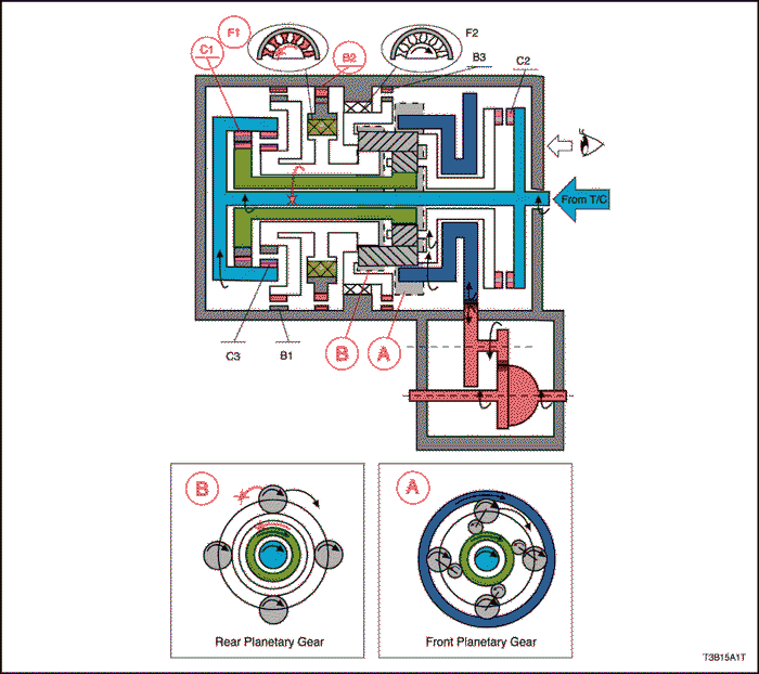
| D | 1st | ON | ON | OFF | ON | OFF | OFF | OFF | OFF | OFF | OFF | ON |
| 1 | 1st | ON | ON | OFF | ON | OFF | OFF | OFF | OFF | ON | OFF | ON |
Position
|
Solenoid
|
Clutch
|
Brake
|
1 way Clutch
|
||||||||
Shift 1
|
Shift 2
|
Timing
|
C1
|
C2
|
C3
|
B1
|
B2
|
B3
|
F1
|
F2
|
||
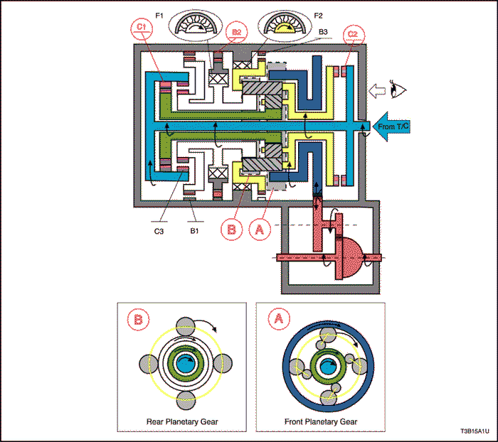
| D | 2nd | ON | OFF | OFF | ON | OFF | OFF | OFF | ON | OFF | ON | OFF |
| 2 | 2nd | ON | OFF | OFF | ON | OFF | OFF | ON | ON | OFF | ON | OFF |
Position
|
Solenoid
|
Clutch
|
Brake
|
1 way Clutch
|
||||||||
Shift 1
|
Shift 2
|
Timing
|
C1
|
C2
|
C3
|
B1
|
B2
|
B3
|
F1
|
F2
|
||
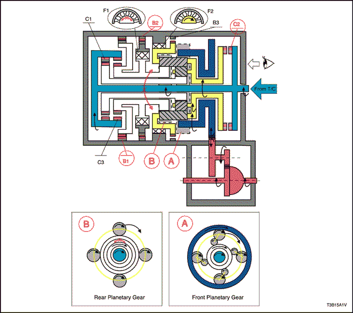
| D | 3rd | OFF | OFF | OFF | ON | ON | OFF | OFF | ON | OFF | OFF | OFF |
Position
|
Solenoid
|
Clutch
|
Brake
|
1 way Clutch
|
||||||||
Shift 1
|
Shift 2
|
Timing
|
C1
|
C2
|
C3
|
B1
|
B2
|
B3
|
F1
|
F2
|
||
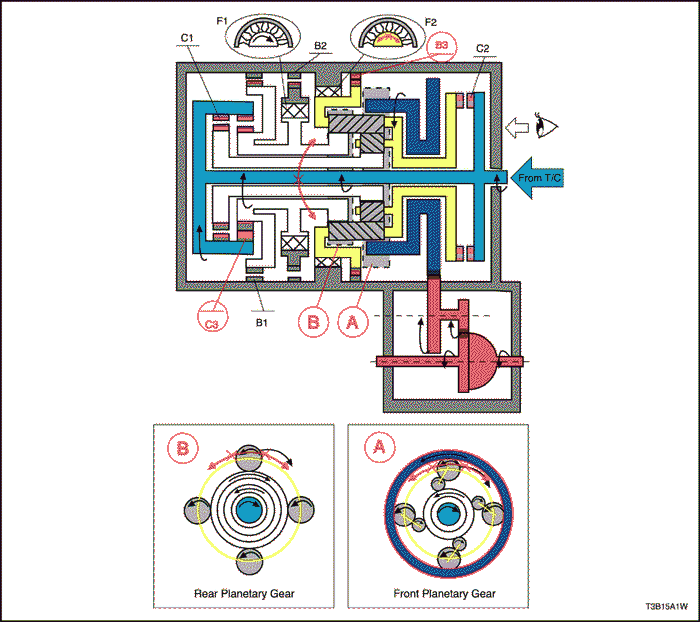
| D | 4th | OFF | ON | OFF | OFF | ON | OFF | ON | ON | OFF | OFF | OFF |
Position
|
Solenoid
|
Clutch
|
Brake
|
1 way Clutch
|
||||||||
Shift 1
|
Shift 2
|
Timing
|
C1
|
C2
|
C3
|
B1
|
B2
|
B3
|
F1
|
F2
|
||
| R | V<9km/h | ON | ON | ON | OFF | OFF | ON | OFF | OFF | ON | OFF | OFF |
| V≥9km/h | ON | ON | ON | OFF | OFF | OFF | OFF | OFF | OFF | OFF | OFF | |
| © Copyright Chevrolet Europe. All rights reserved |


