Aveo |
||||||||
|
||||||||
|
Application
|
N•m
|
Lb-Ft
|
Lb-In
|
|
Backup Lamp Switch
|
20
|
15
|
-
|
|
Bearing Plate Bolts
|
22
|
16
|
-
|
|
Bearing Retainer Bolts, Right Side
|
25
|
18
|
-
|
|
Bearing-Adjusting Ring-Retainer Plate Bolt
|
5
|
-
|
44
|
|
Clutch-Release Cylinder Retaining Bolts
|
20
|
15
|
-
|
|
Damping Block Connection Nut and Bolt
|
85
|
63
|
-
|
|
Differential Cover Bolts
|
40
|
30
|
-
|
|
Fifth-Gear Fork Bolts
|
22
|
16
|
-
|
|
Fifth-Gearshift Connector Bolts
|
7
|
-
|
62
|
|
Flywheel Inspection Cover Bolts
|
7
|
-
|
62
|
|
Gearshift Housing Bolts
|
7
|
-
|
62
|
|
Gearshift Lever Cover Bolts
|
22
|
16
|
-
|
|
Input Driveshaft Detent Screw
|
15
|
11
|
-
|
|
Rear Damping Block Retaining Bolts
|
55
|
41
|
-
|
|
Rear Mounting Bracket Bolts
|
75
|
55
|
-
|
|
Ring-Gear Bolts
|
70
|
52
|
-
|
|
Rod Clamp Bolt
|
16
|
12
|
-
|
|
Speedometer Housing Retaining Bolt
|
4
|
-
|
35
|
|
Speedometer-Driven Gear Bolt
|
5
|
-
|
44
|
|
Transaxle Cover Bolts
|
18
|
13
|
-
|
|
Transaxle Lower Retaining Bolts(a)
|
75
|
55
|
-
|
|
Transaxle Lower Retaining Bolt(b)
|
20
|
15
|
-
|
|
Transaxle Lower Retaining Bolts(c)
|
30
|
22
|
-
|
|
Transaxle Upper Retaining Bolts
|
75
|
55
|
-
|
|
Transaxle Upper Mounting Bracket Bolts
|
60
|
44
|
-
|
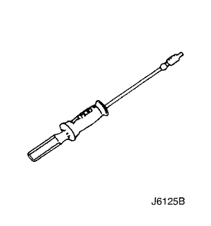 |
J-6125-B
Slide Hammer
|
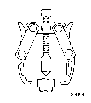 |
J-22888-20-A
Bearing Puller with
J-22888-35
Puller Legs
|
 |
J-22912-01
Universal Bearing Puller
|
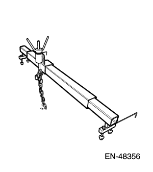 |
EN-48356
Engine Fixture
|
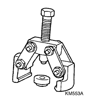 |
KM-553-A
Fifth-Gear Puller
|
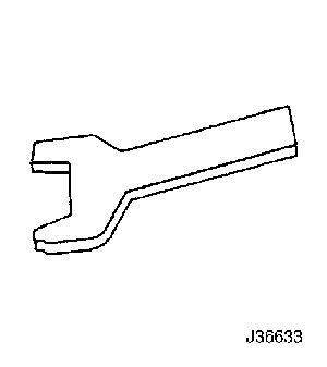 |
J-36633
Snap Ring Retainer
|
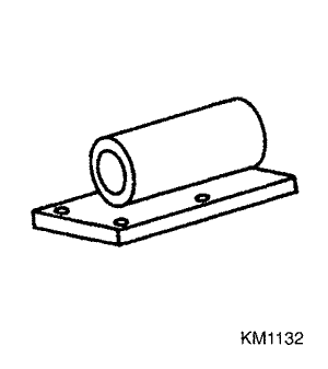 |
KM-113-2
Base
|
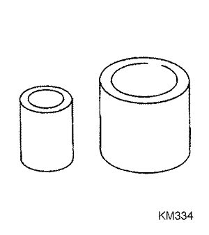 |
KM-334
Installer Sleeve
|
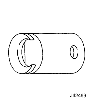 |
J-42469
Shift Rod Remover
|
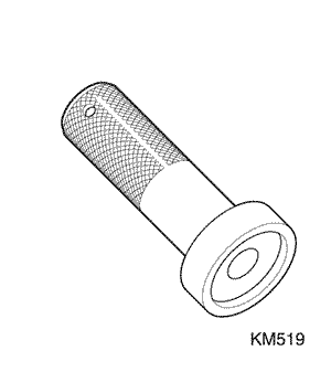 |
KM-519
Ring Installer
|
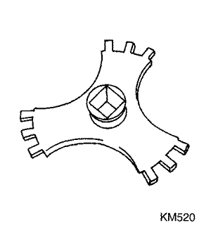 |
KM-520
Remover/Installer
|
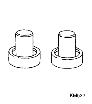 |
KM-522
Installer
|
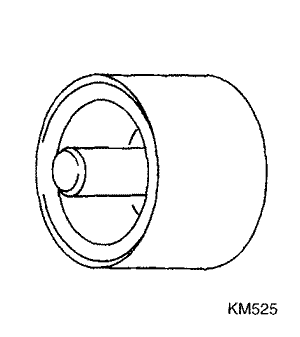 |
KM-525
Installer
|
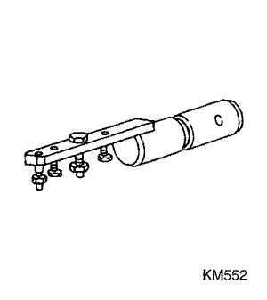 |
KM-552
Fixture
|
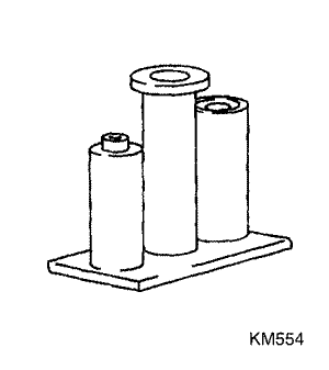 |
KM-554
Installer
|
|
Checks
|
Action
|
|
Check for a knock at low speeds.
|
|
|
Check for a noise most pronounced on turns.
|
|
|
Check for a clunk upon acceleration or deceleration.
|
|
|
Check for a clunking noise in turns.
|
|
|
Check for a vibration.
|
|
|
Check for a noise in the NEUTRAL gear with the engine running.
|
|
|
Check for a noise in the first gear (1) only.
|
|
|
Check for a noise in the second gear (2) only.
|
|
|
Check for a noise in the third gear (3) only.
|
|
|
Check for a noise in the fourth gear (4) only.
|
|
|
Check for a noise in the fifth gear (5) only.
|
|
|
Check for a noise in the reverse (R) gear only.
|
|
|
Check for a noise in all gears.
|
|
|
Check for the transaxle slipping out of gear.
|
|
|
Check for a leak in the area of the clutch.
|
|
|
Check for a leak at the center of the transaxle.
|
|
|
Check for a leak at the differential.
|
|
|
Check for a hard shift.
|
|
|
Check for a clashing of gears.
|
|

| © Copyright Chevrolet Europe. All rights reserved |


