SECTION 6A
POWER STEERING SYSTEM
SPECIFICATIONS
Fastener Tighteming Specifications
|
Application
|
N•m
|
Lb-Ft
|
Lb-In
|
|
Air Cleaner Housing Bolts
|
12
|
-
|
106
|
|
Power Steering Fluid Reservoir Attaching Bolts
|
10
|
-
|
89
|
|
Power Steering Line Fittings-Cylinder End
|
28
|
21
|
-
|
|
Power Steering Line Fittings-Valve End
|
18
|
13
|
-
|
|
Power Steering Pump Pressure Line Union Nut
|
28
|
21
|
-
|
|
Steering Gear Inlet and Outlet Pipe Fittings
|
28
|
21
|
-
|
|
Power Steering Pressure Line Retaining Clamp Bolt
|
25
|
18
|
-
|
|
Power Steering Return Line Retaining Clamp Nuts
|
8
|
-
|
70
|
|
Power Steering Suction Line Retaining Clamp Nuts
|
8
|
-
|
70
|
SPECIAL TOOLS
Special Tools Table
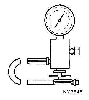
 
|
KM-354-B
Pressure Test Gauge Kit
|
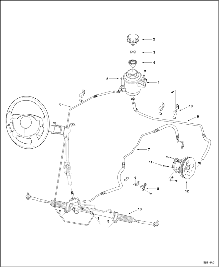
COMPONENT LOCATOR
Power Steering System
- Power Steering Oil Tank
- Power Steering Oil Tank Cap
- Power Steering Oil Tank Sponge
- Power Steering Oil Tank Shield
- Power Steering Oil Tank Nut
- Oil Return Hose
- Power Steering Pump High Pressure Pipe.
- Clamp
- Oil Suction Hose
- Clamp
- Power Steering Pump Bolt
- Power Steering Pump
- Power Steering Gear Set
DIAGNOSIS
Power Steering System Pressure Test
Tools Required
KM-354-B Pressure Test Gauge Kit
Check the fluid pressure as follows to determine whether the trouble is in the pump or the gear unit.
Test Procedure
- Check the power steering fluid level and the power steering pump belt tension. Refer to "Checking and Adding Fluid" in this section and Section 6B, Power Steering Pump.
- Disconnect the high pressure line at the pump. Use a small container to catch any fluid.
- Connect the hose of the pressure test gauge kit KM-354-B to the power steering pressure hose from the power steering pump.
- Place the gear selector lever in PARK (automatic transaxle-equipped vehicles) or NEUTRAL (manual transaxle-equipped vehicles). Set the parking brake.
- Open the gauge valve fully.
- Start the engine and let it idle.
- Turn the steering wheel from lock-to-lock several times to warm the fluid to operating temperature.
- Increase the engine speed to 1,500 rpm.
Notice : The power steering pump could be damaged if the valve is fully closed for more than five seconds.
- Close the gauge valve fully, and read the pressure. The pump pressure with the valve closed should be between 7 088 kPa to 8 619 kPa (1,028 psi to 1,250 psi).
- Close the gauge valve fully, and read the pressure. The pump pressure with the valve closed should be between 7 088 kPa to 8 619 kPa (1,028 psi to 1,250 psi).
- Immediately open the gauge valve fully.
- Turn the steering wheel all the way to the left and the right. If the pressure is within the specified limits, the problem is not in the pump. Check the power steering gear for leaks.
Power Steering System Leak Test
General Procedure
Inspect the following:
- The fluid reservoir for overfill.
- Fluid for aeration and overflow.
- The hoses for loose connections.
- The torsion bar, stub shaft and adjuster seals for leaks.
- The component sealing surfaces for damage.
Important : Verify the exact point of the leak. The point from which the fluid is dripping is not necessarily the point at which the system is leaking. When service is required, clean the leak area upon disassembly, replace the leaking seal, check the component sealing surfaces for damage and reset the torque bolt to specifications, where required.
External Leak Check
The purpose of this procedure is to pinpoint the location of the leak. In some cases, the leak can be easily located, but seepage-type leaks may be harder to find. To locate seepage leaks, use the following method:
- With the engine off, wipe dry the complete power steering system.
- Check the power steering fluid level in the pump's reservoir. Adjust the fluid level as necessary. Refer to "Checking and Adding Fluid" in this section.
Notice : Do not hold the steering wheel at a stop for any length of time as this can damage the power steering pump.
- Start the engine. Turn the steering wheel counterclockwise and clockwise from stop to stop several times.
- Start the engine. Turn the steering wheel counterclockwise and clockwise from stop to stop several times.
- Find the exact area of the leak and repair it.
MAINTENANCE AND REPAIR
ON-VEHICLE SERVICE
Bleeding the Power Steering System
If the power steering hydraulic system has been serviced, an accurate fluid level reading cannot be obtained until the air is bled from the system. Follow these steps to bleed the air from the system.
- Turn the wheels all the way to the left and add the power steering fluid to the MIN mark on the fluid level indicator.
Notice : When adding fluid or making a complete fluid change, always use DEXRON® II D power steering fluid. Failure to use the proper fluid will cause hose and seal damage and fluid leaks.
- Start the engine. With the engine running at fast idle, recheck the fluid level. If necessary, add fluid to bring the level up to the MIN mark.
- Bleed the system by turning the wheels from side to side without reaching the stop at either end. Keep the fluid level at the MIN mark. The air must be eliminated from the fluid before normal steering action can be obtained.
- Return the wheels to the center position. Continue running the engine for two to three minutes.
- Road test the car to be sure the steering functions normally and is free from noise.
- Recheck the fluid level as described in steps 1 and 2. Make sure the fluid level is at the MAX mark after the system has stabilized at its normal operating temperature. Add fluid as needed.
Checking and Adding Fluid
Notice : When adding fluid or making a complete fluid change, always use DEXRON® II D power steering fluid. Failure to use the proper fluid will cause hose and seal damage and fluid leaks.
- The power steering fluid level is indicated either by marks on a see-through fluid reservoir or by marks on a fluid level indicator on the fluid reservoir cap.
- If the fluid is warmed up to 66°C (150°F), the fluid level should be between the MAX and MIN marks. Add fluid as needed.
- If the fluid is cool, 21°C (70°F), the fluid level should be at the MIN mark. Add fluid as needed.
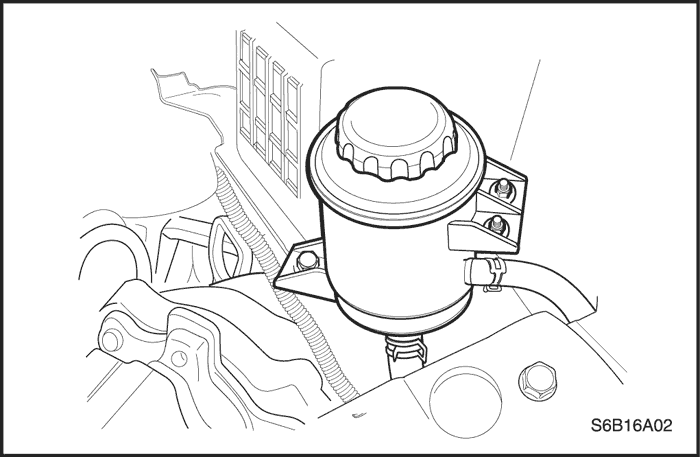
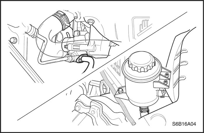
Fluid Reservoir
Removal Procedure
- Siphon the power steering fluid from the fluid reservoir.
- Loosen the hose clamps and remove both hoses.
Notice : The hoses must be clogged just after removal to prevent foreign material contaminants from entering the power steering system. Contamination could lead to deterioration of the steering components and loss of steering action.
- Remove the fluid reservoir attaching bolts and remove the fluid reservoir.
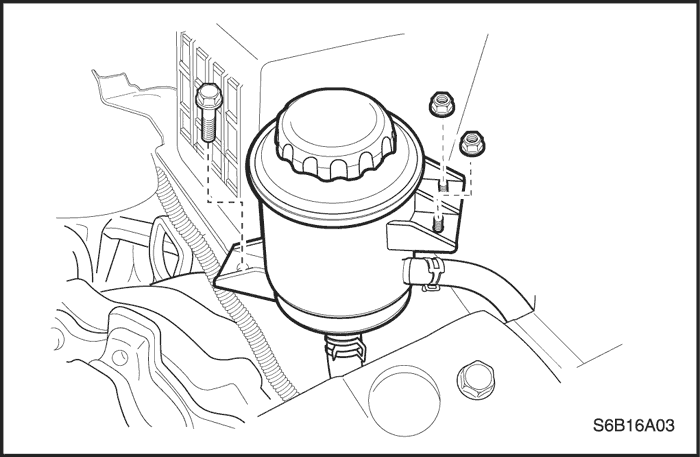
Installation Procedure
- Attach the fluid reservoir with the power steering fluid reservoir attaching bolts.
Tighten
Tighten the power steering fluid reservoir attaching bolts to 10 N•m (89 lb-in).
- Connect both hoses and secure the hose clamps.
Notice : When adding fluid or making a complete fluid change, always use DEXRON® II D power steering fluid. Failure to use the proper fluid will cause hose and seal damage and fluid leaks.
- Fill the fluid reservoir with power steering fluid.
- Inspect for leaks. If there are leaks, correct the cause of the leaks and bleed the system. Refer to "Bleeding the Power Steering System"in this section.
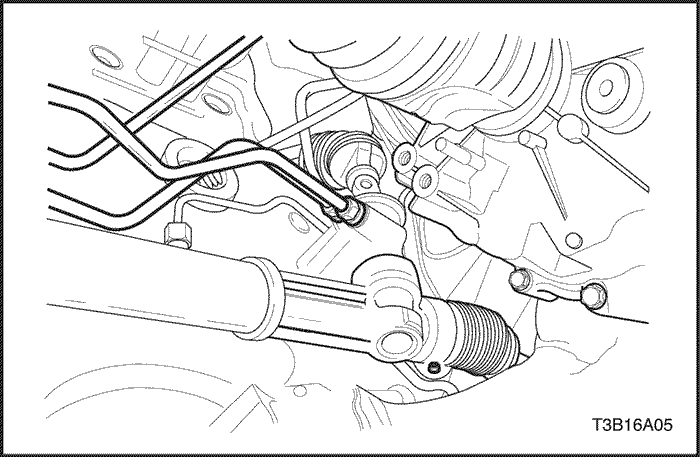
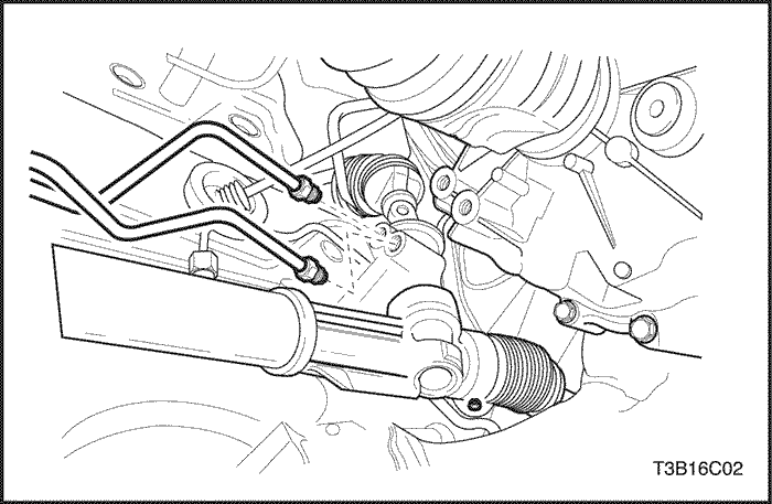
Power Steering Gear Cylinder Pipes
Removal Procedure
- Siphon the power steering fluid from the fluid reservoir.
- Disconnect and remove the steering gear cylinder pipes at the rack and pinion housing. Remove the O-ring seals from the housing.
Installation Procedure
- Install new O-rings onto the cylinder pipes. Install the steering gear cylinder pipes into the rack and pinion housing.
Tighten
Tighten the power steering line fittings at the cylinder end to 28 N•m (21 lb-ft).
Tighten
Tighten the power steering line fittings at the valve end to 18 N•m (13 lb-ft).
- Fill the fluid reservoir with power steering fluid.
- Inspect for leaks. If there are leaks, correct the cause of the leaks and bleed the system. Refer to "Bleeding the Power Steering System"in this section.
- Lower the vehicle.
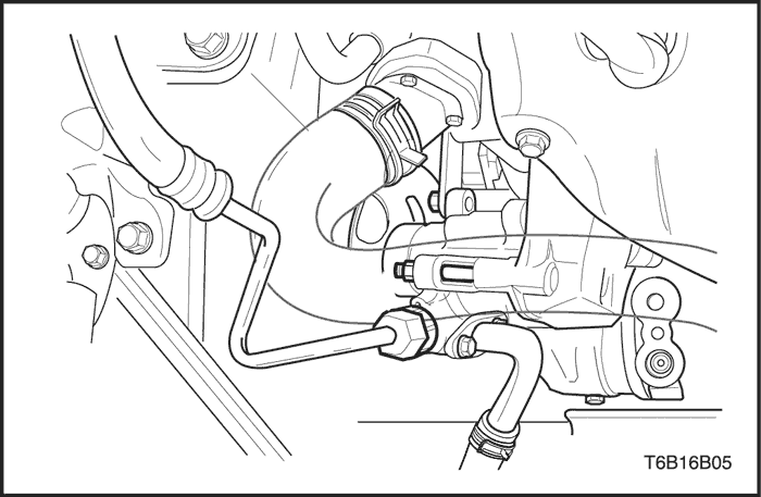
Power Steering Hoses and Pipes
Removal Procedure
- Siphon the power steering fluid from the fluid reservoir.
- Disconnect the pressure line pipe from the outlet connections on the power steering pump.
- Remove the air cleaner housing, if needed.
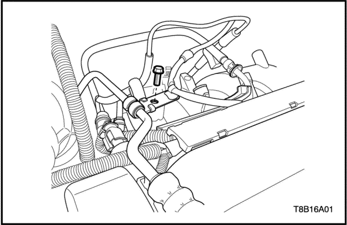
- Remove the pressure pipe retaining clamp bolt near the engine cylinder head.
- Remove the return pipe retaining clamp nuts near the left side body panel.
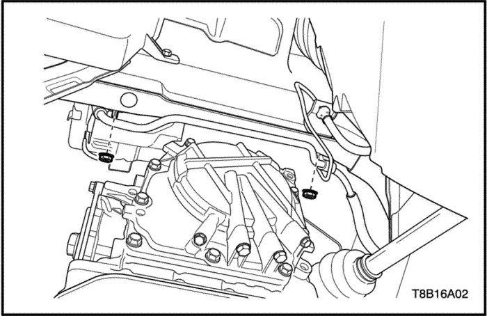
- Disconnect the pressure and return line inlet pipe from the steering gear.
- Disconnect the return line hose from the power steering fluid reservoir.
- Remove the power steering pump pressure line and return line from the vehicle.
Installation Procedure
- Install the power steering pump pressure line and return line.
- Connect the return line hose to the power steering fluid reservoir.
- Connect the pressure and return line inlet pipe to the steering gear.
Tighten
Tighten the steering gear inlet pipe fitting to 28 N•m (21 lb-ft).
- Install the pressure pipe retaining clamp bolt.
Tighten
Tighten the power steering pressure pipe retaining clamp bolt to 25 N•m (18 lb-ft).
- Install the return pipe retaing clamp nuts.
Tighten
Tighten the power steering return pipe retaining clamp nut to 8 N•m (70 lb-in).
- Connect the pressure line pipe and the supply line hose to the inlet and outlet connections on the power steering pump.
Tighten
Tighten the power steering pump pressure line union nut to 28 N•m (21 lb-ft).
- On DOHC engines, Install the air cleaner housing, if removed.
Tighten
Tighten the air cleaner housing bolts to 12 N•m (106 lb-in).
- Fill the fluid reservoir with power steering fluid.
- Inspect for leaks. If there are leaks, correct the cause of the leaks and bleed the system. Refer to "Bleeding the Power Steering System"
in this section.
Fluid Reservoir Suction Hose
Removal Procedure
- Siphon the power steering fluid from the fluid reservoir.
- Disconnect the suction hose from the steering pump.
- Disconnect the suction hose from the fluid reservoir.
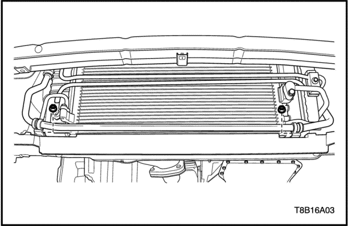
- Remove the suction pipe retaining clamp nuts under the radiator.
- Remove the fluid reservoir suction hose from the vehicle.
Installation Procedure
- Connect the suction hose to the fluid reservoir.
- Connect the suction hose to the steering pump.
- Install the suction pipe retaining clamp nuts.
Tighten
Tighten the power steering suction pipe retaining clamp nuts to 8 N•m (70 lb-in).
Notice : When adding fluid or making a complete fluid change, always use DEXRON® II D power steering fluid. Failure to use the proper fluid will cause hose and seal damage and fluid leaks.
- Fill the fluid reservoir with power steering fluid.
- Inspect for leaks. If there are leaks, correct the cause of the leaks and bleed the system. Refer to "Bleeding the Power Steering System in this Section
GENERAL DESCRIPTION AND SYSTEM OPERATION
Power Steering System
General Description
The power steering system consists of three components: the power steering pump, the power steering fluid reservoir and the the power steering rack and pinion gear. The power steering pump is a vane-type pump providing hydraulic pressure for the system and is powered by the engine. It draws on the power steering fluid reservoir, which in turn is connected to the power steering gear. A pressure-relief valve inside the flow control valve limits the pump pressure. The power steering rack and pinion gear has a rotary control valve which directs hydraulic fluid coming from the power steering pump to one side or the other side of the rack piston. The integral rack piston is attached to the rack. The rack piston converts hydraulic pressure to a linear force which moves the rack to the left or the right. The force is then transmitted through the inner and the outer tie rods to the steering knuckles, which turn the wheels.