Aveo |
||||||||
|
||||||||
|
Application
|
N•m
|
Lb-Ft
|
Lb-In
|
|
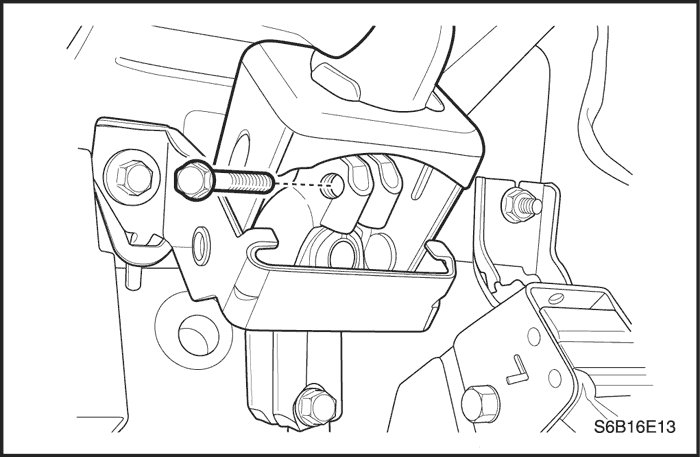
Coupling Flange Pinch Bolt
|
22
|
16
|
-
|
|
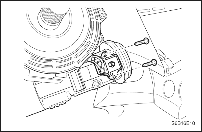
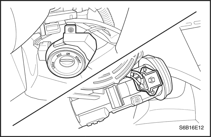
Ignition Switch Retaining Screw
|
2
|
-
|
18
|
|
Key Hole Illumination Screw
|
2
|
-
|
18
|
|
Key Reminder Switch Screw
|
2
|
-
|
18
|
|
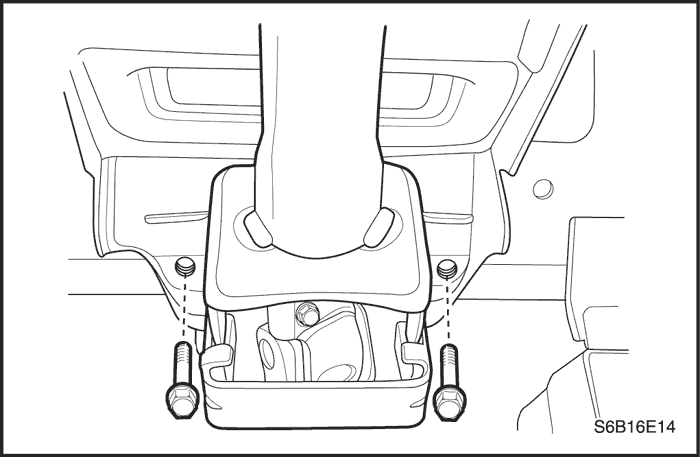
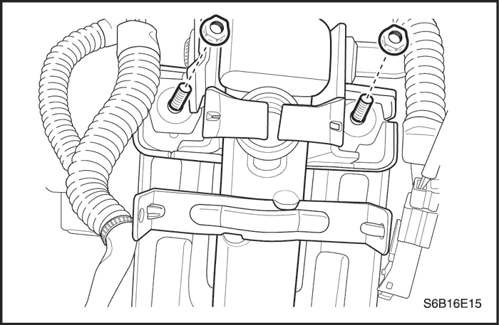
Steering Column Jacket Assembly Bracket Nuts
|
22
|
16
|
-
|
|
Steering Wheel Nut
|
38
|
28
|
-
|
|
Upper and Lower Steering Column Cover Panel Screws
|
3
|
-
|
27
|
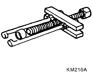 |
KM-210-A
Steering Wheel Puller
|
|
Checks
|
Action
|
|
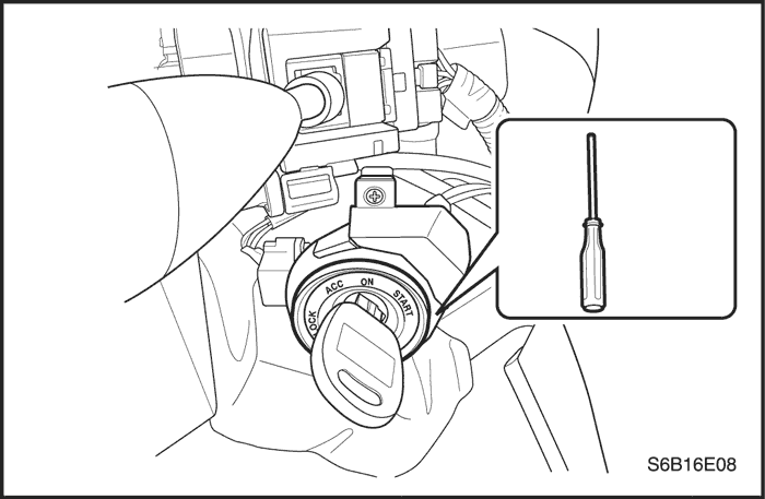
Check the lock cylinder for damage.
|
Replace the lock cylinder.
|
|
Check the ignition switch for lack of free movement.
|
Lubricate the ignition switch.
|
|
Check the steering column housing for binding or damage.
|
Remove the steering shaft and clear the steering column housing. Replace the steering column housing as needed.
|
|
Checks
|
Action
|
|
Check the lock cylinder for damage.
|
Replace the lock cylinder.
|
|
Check the ignition switch for a lack of free movement.
|
Lubricate the ignition switch.
|
|
Check the steering column housing for binding or damage.
|
Remove the steering shaft and clear the steering column housing. Replace the steering column housing as needed.
|
|
Checks
|
Action
|
|
Check the lock cylinder for damage.
|
Replace the lock cylinder.
|
|
Check the ignition switch for lack of free movement.
|
Lubricate the ignition switch.
|
|
Check for extreme misalignment of the housing to the cover.
|
Realign the cover on the housing. Replace the cover as needed.
|
|
Check for a bent ignition switch mounting bracket.
|
Replace the ignition switch mounting bracket.
|
|
Checks
|
Action
|
|
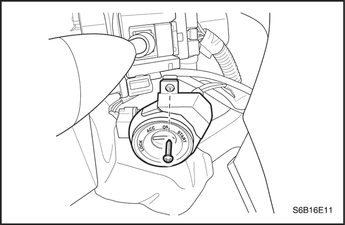
Check to see that the ignition switch is set correctly.
|
Reset the ignition switch.
|
|
Check the lock cylinder for damage.
|
Replace the lock cylinder.
|
|
Checks
|
Action
|
|
Check the steering gear-to-column joints for improper installation.
|
Tighten the coupling flange pinch bolts. Replace the coupling flange as needed.
|
|
Check for column misalignment.
|
Replace the alignment spacer.
|
|
Check the steering shaft bearing for wear or damage.
|
Replace the steering shaft bearing.
|
|
Check the spherical joint for lack of lubrication.
|
Lubricate the spherical joint.
|
|
Check the steering shaft for lack of lubrication.
|
Lubricate the steering shaft bearing.
|
|
Check the shaft lock snap ring for improper seating.
|
Adjust the shaft lock snap ring. Replace the shaft lock snap ring as needed.
|
|
Checks
|
Action
|
|
Check the steering shaft bearing for wear or damage.
|
Replace the steering shaft bearing.
|
|
Check for column misalignment.
|
Replace the alignment spacer.
|
|
Check for an improperly installed or deformed dust seal.
|
Replace the dust seal.
|
|
Check for a damaged upper or lower bearing.
|
Replace the upper or the lower bearing.
|
|
Check the steering shaft universal joints for a lack of free movement.
|
Lubricate the steering shaft universal joint. Replace the steering shaft universal joint as needed.
|
|
Checks
|
Action
|
|
Check the steering column bracket mounting bolts for improper installation.
|
Tighten the steering column bracket mounting bolts.
|
|
Check for broken weld nuts on the steering column jacket.
|
Replace the steering column jacket.
|
|
Check for loose steering column housing-to-steering column jacket support screws.
|
Tighten the support screws.
|
|
Checks
|
Action
|
|
Check for excessive clearance between the holes in the steering wheel support or the housing and the pivot-pin diameters.
|
Replace the pivot pins with pivot pins of the correct size.
|
|
Check to see if the upper bearing is seated correctly in the housing.
|
Correctly seat the upper bearing. Replace the upper bearing as needed.
|
|
Check for loose steering column housing support screws.
|
Tighten the steering column housing support screws.
|
|
Checks
|
Action
|
|
Check for worn upper tilt bumpers.
|
Replace the upper tilt bumpers.
|
|
Check for tilt spring binding.
|
Adjust the tilt spring. Replace the tilt spring as needed.
|
|
Checks
|
Action
|
|
Check the turn signal switch for an improper installation.
|
Remove and inspect the turn signal switch. Reinstall the switch.
|
|
Check the cancelling mechanism for broken or missing components.
|
Replace the cancelling mechanism.
|
|
Check the turn signal switch housing for foreign material.
|
Remove any foreign material.
|
|
Checks
|
Action
|
|
Check the cancelling mechanism for broken or missing components.
|
Replace the cancelling mechanism.
|
|
Checks
|
Action
|
|
Check the turn signal/dimmer switch and turn signal/dimmer switch lever for improper installation.
|
Remove and inspect the turn signal/dimmer switch and signal/dimmer switch lever. Reinstall the signal/dimmer switch and signal/dimmer switch lever.
|
|
Check the signal/dimmer switch housing for foreign material.
|
Remove any foreign material.
|
|
Checks
|
Action
|
|
Check for a broken lane change pressure pad or a broken spring hanger.
|
Replace the lane change pressure pad or the spring hanger.
|
|
Check for improper functioning of the lane change spring.
|
Replace the lane change spring.
|
|
Check the turn signal switch for improper installation.
|
Replace the turn signal switch.
|
|
Checks
|
Action
|
|
Check for an inoperative turn signal flasher.
|
Replace the turn signal flasher.
|
|
Check for a faulty turn signal switch.
|
Replace the turn signal switch.
|
|
Check the chassis-to-column connector for an improper connection.
|
Reconnect the chassis-to-column connector.
|
|
Checks
|
Action
|
|
Check for an inoperative turn signal flasher.
|
Replace the turn signal flasher.
|
|
Check for a faulty turn signal switch.
|
Replace the turn signal switch.
|
|
Check the chassis-to-column connector for an improper connection.
|
Reconnect the chassis-to-column connector.
|
|
Checks
|
Action
|
|
Check for a faulty turn signal switch.
|
Replace the turn signal switch.
|
|
Check the chassis-to-column connector for an improper connection.
|
Reconnect the chassis-to-column connector.
|
|
Checks
|
Action
|
|
Check the chassis-to-column connector for an improper connection.
|
Reconnect the chassis-to-column connector.
|
|
Checks
|
Action
|
|
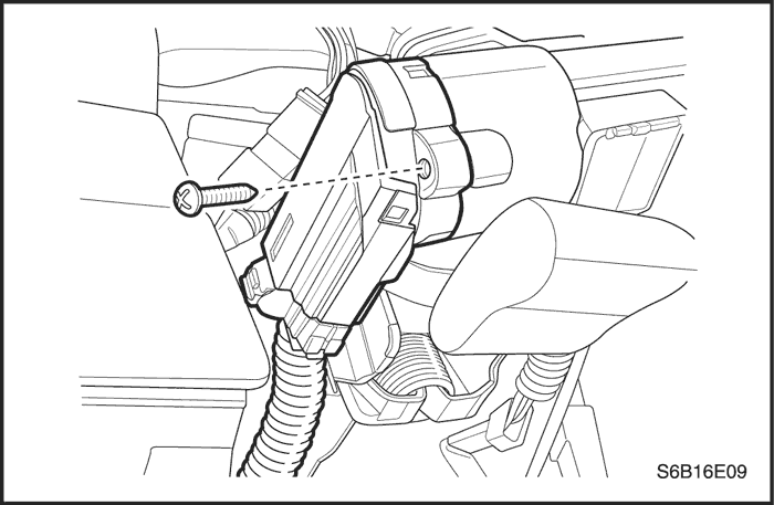
Check the ignition switch for damage.
|
Replace the ignition switch.
|
|
Check the ignition switch for improper installation.
|
Remove and inspect the ignition switch. Reinstall the ignition switch.
|
|
Check the ignition switch electrical connector for improper installation.
|
Reconnect the ignition switch electrical connector. Replace the ignition switch electrical connector.
|
|
Checks
|
Action
|
|
Check the ignition switch for damage.
|
Replace the ignition switch.
|
|
Check the ignition switch for improper installation.
|
Remove and inspect the ignition switch. Reinstall the ignition switch.
|
|
Checks
|
Action
|
|
Check the wiper switch for damage.
|
Replace the wiper switch.
|
|
Check the wiper switch for improper installation.
|
Remove and inspect the wiper switch. Reinstall the wiper switch.
|
| © Copyright Chevrolet Europe. All rights reserved |


