Aveo |
||||||||
|
||||||||
|
Application
|
Description
|
||
|
Type
|
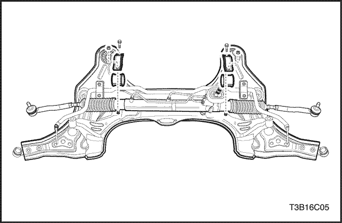
Rack & Pinion
|
||
|
Rack Gain
|
32.17 mm/rev
|
||
|
Rack Stroke
|
139 ± 1.0 mm
|
||
|
Steering Angle
|
Inner
|
39.5°
|
|
|
Outer
|
33°
|
||
|
Rack
|
Straight (Bending Limit)
|
0.1 mm
|
|
|
Application
|
N•m
|
Lb-Ft
|
Lb-In
|
|
Coupling Flange Pinch Bolt
|
22
|
16
|
-
|
|
Outer Tie Rod Lock Nut
|
45
|
33
|
-
|
|
Outer Tie Rod Hex Nut
|
50
|
37
|
-
|
|
Steering Gear Retaining Bracket Nuts or Bolts
|
60
|
44
|
-
|
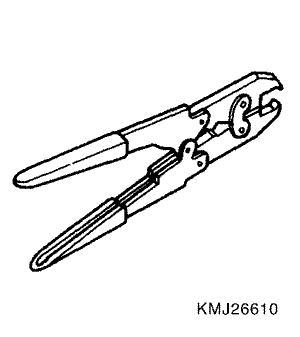 |
KM-J-26610
Installer
|
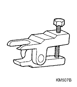 |
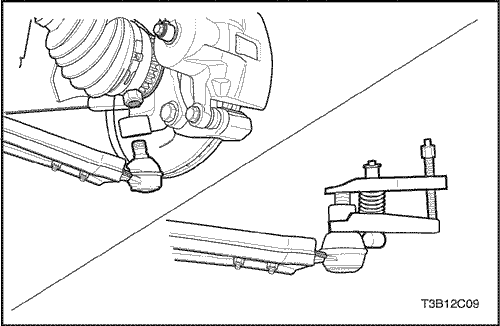
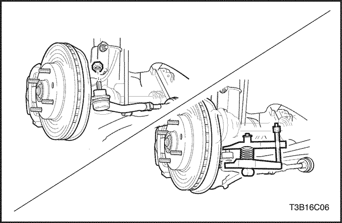
KM-507-B
Ball Joint Remover
|
|
Checks
|
Action
|
|
Check the steering gear adjustment.
|
Perform straight-ahead check.
|
|
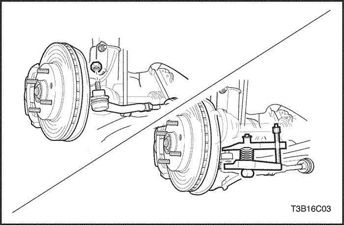
Check the wheel bearing for wear or damage.
|
Replace the wheel bearing.
|
|
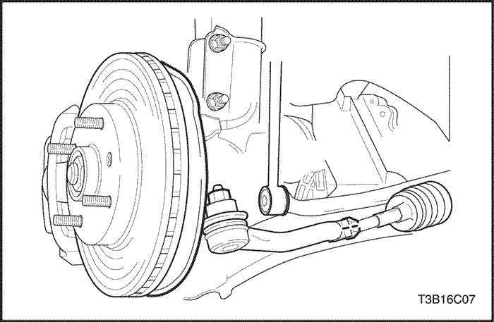
Check the outer tie rods for improper installation.
|
Tighten the tie rods.
|
|
Checks
|
Action
|
|
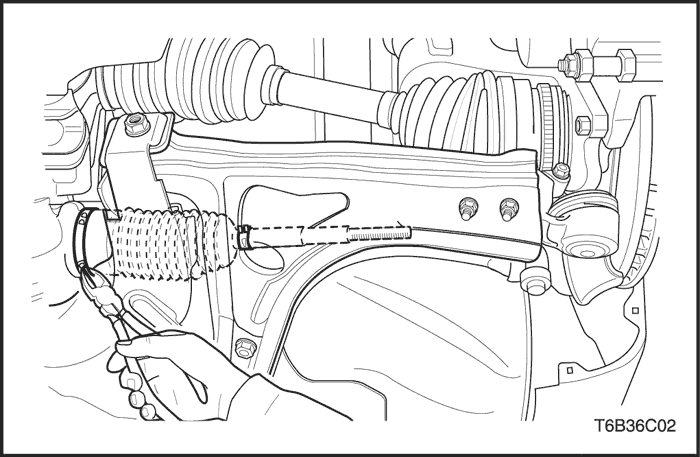
Check the steering gear for improper and insufficient lubrication.
|
Lubricate the rack assembly. Lubricate the pinion assembly.
|
|
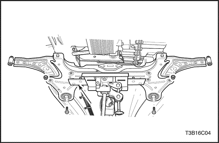
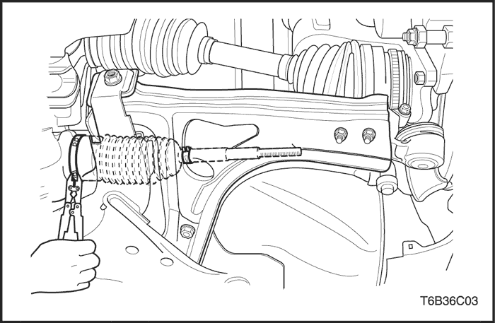
Check the steering gear mounting for improper installation.
|
Tighten the steering gear mounting bolts and the nuts.
|
|
Check the outer tie rods for improper installation.
|
Tighten the tie rods.
|
| Step | Action | Value(s) | Yes | No |
| 1 |
Place the steering wheel in the straight-ahead position
Is the wheel in the correct position?
|
-
|
Go to Step 2
|
-
|
| 2 |
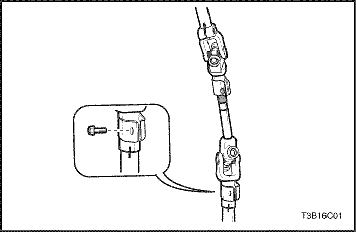
Is the steering coupling flange pinch bolt lying horizontally?
|
-
|
Go to Step 3
|
Go to Step 4
|
| 3 |
Is the steering wheel off center by more than 5 degrees?
|
-
|
Go to Step 5
|
Go to Step 6
|
| 4 |
The pinion is displaced on the rack. The steering pinion position must be corrected.
Is the repair complete?
|
-
|
Go to Step 2
|
-
|
| 5 |
Remove steering wheel and center on the spindle splines.
Is the repair complete?
|
-
|
Go to Step 3
|
-
|
| 6 |
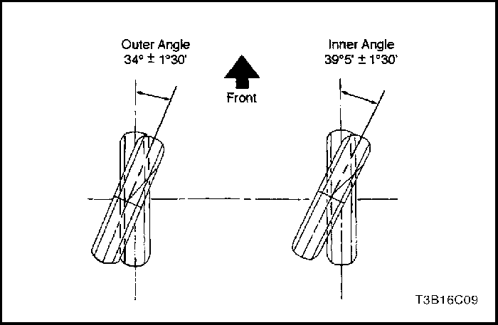
Turn the steering wheel all the way to the right. Measure the inner and the outer angles of the tire centerline compared to the straight-ahead centerline. Do the angles match the value specified?
|
Inner angle: 39°5' ± 1°30'
Outer angle: 34° ± 1°30'
|
System OK
|
Go to Step 7
|
| 7 |
The rack assembly was not assembled correctly. Repair as needed.
Is the repair complete?
|
-
|
Go to Step 6
|
-
|
| Step | Action | Value(s) | Yes | No |
| 1 |
Place the steering wheel in the straight-ahead position.
Is the wheel in the correct position?
|
-
|
Go to Step 2
|
-
|
| 2 |
Is the steering coupling flange pinch bolt lying horizontally?
|
-
|
Go to Step 3
|
Go to Step 4
|
| 3 |
Is the steering wheel off center by more than 5 degrees?
|
-
|
Go to Step 5
|
Go to Step 6
|
| 4 |
The pinion is displaced on the rack. The steering pinion position must be corrected.
Is the repair complete?
|
-
|
Go to Step 2
|
-
|
| 5 |
Remove steering wheel and center on the spindle splines.
Is the repair complete?
|
-
|
Go to Step 3
|
-
|
| 6 |
Turn the steering wheel all the way to the right. Measure the inner and the outer angles of the tire centerline compared to the straight-ahead centerline. Do the angles match the value specified?
|
Inner angle: 39°5' ± 1°30'
Outer angle: 34° ± 1°30'
|
System OK
|
Go to Step 7
|
| 7 |
The rack assembly was not assembled correctly.
Repair, as needed.
Is the repair complete?
|
-
|
Go to Step 6
|
-
|
| © Copyright Chevrolet Europe. All rights reserved |


