Aveo |
||||||||
|
||||||||
|
Application
|
N•m
|
Lb-Ft
|
Lb-In
|
|
Blower Motor Resistor Screws
|
1.2
|
-
|
11
|
|
Control Assembly Retaining Screws
|
2
|
-
|
18
|
| Step | Action | Value(s) | Yes | No |
| 1 |
Check the fuse F19.
Is fuse F19 blown?
|
-
|
Go to Step 2
|
Go to Step 3
|
| 2 |
Replace fuse F19.
Is the repair complete?
|
-
|
System OK
|
-
|
| 3 |
Is the voltage within the specified value?
|
11-14 v
|
Go to Step 4
|
Go to Step 5
|
| 4 |
Is the repair complete?
|
-
|
System OK
|
-
|
| 5 |
Check the voltage between terminal B13 and ground.
Is this voltage as specified?
|
0 v
|
Go to Step 6
|
Go to Step 7
|
| 6 |
Is the repair complete?
|
-
|
System OK
|
-
|
| 7 |
Is the repair complete?
|
-
|
System OK
|
-
|
| Step | Action | Value(s) | Yes | No |
| 1 |
Check the coolant level.
Is the coolant level correct?
|
-
|
Go to Step 3
|
Go to Step 2
|
| 2 |
Add coolant as needed.
Is the heater operating?
|
-
|
System OK
|
Go to Step 3
|
| 3 |
Does the digit flash on and off?
|
-
|
Go to Step 4
|
Go to Step 5
|
| 4 |
Run a self-diagnosis circuit check.
Does the display indicate a defect code?
|
-
|
Go to the table for the code that flashes
|
Go to Step 7
|
| 5 |
Observe the blower motor operation.
Is the blower motor functioning at all?
|
-
|
Go to Step 6
|
|
| 6 |
Use the blower push switch to cycle the blower through its different speeds.
Does the motor function at different speeds?
|
-
|
Go to Step 7
|
|
| 7 |
Does the air flow from the different outlets as it should?
|
-
|
Go to Step 9
|
Go to Step 8
|
| 8 |
Is the heater operating?
|
-
|
System OK
|
Go to Step 9
|
| 9 |
Observe the air mix door (AMD) motor while changing the temperature setting from 18 to 32°C (64 to 90°F) and then from 32 to 18°C (90 to 64°F).
Is the AMD motor functioning properly?
|
-
|
Go to Step 10
|
|
| 10 |
Check the coolant hoses for leaks or kinks.
Are the coolant hoses in good condition?
|
-
|
Go to Step 12
|
Go to Step 11
|
| 11 |
Repair any problem with the coolant hoses.
Is the heater operating?
|
-
|
System OK
|
Go to Step 12
|
| 12 |
Check the surge tank cap.
Is the surge tank cap in good condition?
|
-
|
Go to Step 14
|
Go to Step 13
|
| 13 |
Repair or replace the surge tank cap as needed.
Is the heater operating?
|
-
|
System OK
|
Go to Step 14
|
| 14 |
Does the coolant flow?
|
-
|
Go to Step 16
|
Go to Step 15
|
| 15 |
Is the repair complete?
|
-
|
System OK
|
-
|
| 16 |
Check the temperature of the heater inlet and outlet hoses by feel.
Is the heater inlet hose hot and the outlet hose warm?
|
-
|
Go to Step 18
|
Go to Step 17
|
| 17 |
Back flush or replace the heater core.
Is the repair complete?
|
-
|
System OK
|
-
|
| 18 |
Check the vehicle for cold air leaks at the
Are any leaks found?
|
-
|
Go to Step 20
|
Go to Step 19
|
| 19 |
Repair any cold air leaks.
Is the repair complete?
|
-
|
System OK
|
-
|
| 20 |
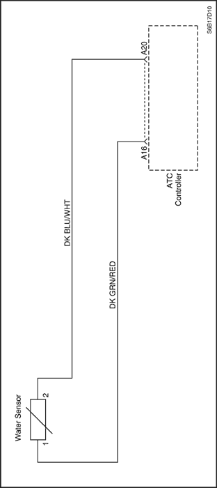
Check the coolant temperature sensor using the tests in "Code 3 - Coolant Temperature Sensor Error."
Is there a problem indicated in the sensor, the sensor wiring, or the controller?
|
-
|
Go to Step 21
|
Go to Step 22
|
| 21 |
Repair or replace the sensor, the wiring, or the controller as required.
Is the repair complete?
|
-
|
System OK
|
-
|
| 22 |
Check the in-car sensor using the tests in "Code 1 - In-Car Sensor Error."
Is there a problem indicated in the sensor, the
sensor wiring, or the controller?
|
-
|
Go to Step 23
|
Go to Step 24
|
| 23 |
Repair or replace the sensor, the wiring, or the controller as required.
Is the repair complete?
|
-
|
System OK
|
-
|
| 24 |
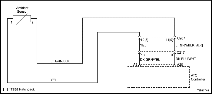
Check the ambient air temperature sensor using the tests in "Code 2 - Ambient Air Temperature Sensor Error."
Is there a problem indicated in the sensor, the sensor wiring, or the controller?
|
-
|
Go to Step 25
|
Go to Step 26
|
| 25 |
Repair or replace the sensor, the wiring, or the controller as required.
Is the repair complete?
|
-
|
System OK
|
-
|
| 26 |
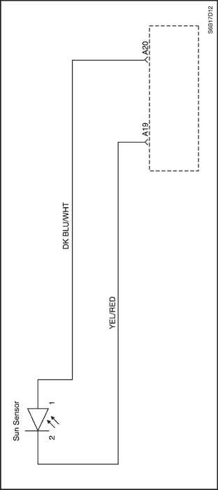
Check the sun sensor using the tests in "Code 5 - Sun Sensor Error."
Is there a problem indicated in the sensor, the sensor wiring, or the controller?
|
-
|
Go to Step 27
|
Go to Step 28
|
| 27 |
Repair or replace the sensor, the wiring, or the controller as required.
Is the repair complete?
|
-
|
System OK
|
-
|
| 28 |
Replace the ATC controller.
Is the repair complete?
|
-
|
System OK
|
-
|
| Step | Action | Value(s) | Yes | No |
| 1 |
Does the digit flash on and off?
|
-
|
Go to Step 2
|
Go to Step 3
|
| 2 |
Run a self-diagnosis circuit check.
Does the display indicate a defect code?
|
-
|
Go to the table for the code that flashes.
|
Go to Step 7
|
| 3 |
Observe the blower motor operation.
Is the blower motor functioning at all?
|
-
|
Go to Step 4
|
|
| 4 |
Use the blower push switch to cycle the blower through its different speeds.
Does the motor function at different speeds?
|
-
|
Go to Step 5
|
|
| 5 |
Does the air flow from the different outlets as it should?
|
-
|
Go to Step 7
|
Go to Step 6
|
| 6 |
Is the heater operating?
|
-
|
System OK
|
Go to Step 9
|
| 7 |
Observe the air mix door motor (AMD) while changing the temperature setting from 18 to 32°C (64 to 90°F) and then from 32 to 18°C (90 to 64°F).
Is the AMD motor functioning properly?
|
-
|
Go to Step 8
|
|
| 8 |
Perform the checks found in "Insufficient Cooling
Diagnosis."
Is the system operating normally now?
|
-
|
System OK
|
Go to Step 9
|
| 9 |
Place the controller in the AUTO mode.
Is smoke taken into the intake port of the in-car sensor?
|
-
|
Go to Step 12
|
Go to Step 10
|
| 10 |
Check the intake hose for the in-car sensor.
Is the hose in good condition?
|
-
|
Go to Step 12
|
Go to Step 11
|
| 11 |
Repair or replace the intake hose.
Is the repair complete?
|
-
|
System OK
|
-
|
| 12 |
Check the in-car sensor using the tests in "Code 1 - In-Car Sensor Error."
Is there a problem indicated in the sensor, the sensor wiring, or the controller?
|
-
|
Go to Step 13
|
Go to Step 14
|
| 13 |
Repair or replace the sensor, the wiring, or the controller as required.
Is the repair complete?
|
-
|
System OK
|
-
|
| 14 |
Check the ambient air temperature sensor using the tests in "Code 2 - Ambient Air Temperature Sensor Error."
Is there a problem indicated in the sensor, the sensor wiring, or the controller?
|
-
|
Go to Step 15
|
Go to Step 16
|
| 15 |
Repair or replace the sensor, the wiring, or the controller, as required.
Is the repair complete?
|
-
|
System OK
|
-
|
| 16 |
Check the sun sensor using the tests in "Code 5 - Sun Sensor Error."
Is there a problem indicated in the sensor, the sensor wiring, or the controller?
|
-
|
Go to Step 17
|
Go to Step 18
|
| 17 |
Repair or replace the sensor, the wiring, or the controller as required.
Is the repair complete?
|
-
|
System OK
|
-
|
| 18 |
Perform the coolant temperature sensor test.
Is the coolant temperature sensor malfunctioning?
|
-
|
Go to Step 19
|
Go to Step 20
|
| 19 |
Replace the coolant temperature sensor.
Is the repair complete?
|
-
|
System OK
|
-
|
| 20 |
Replace the ATC controller.
Is the repair complete?
|
-
|
System OK
|
-
|
| Step | Action | Value(s) | Yes | No |
| 1 |
Does the digit go on and off?
|
-
|
Go to Step 2
|
Go to Step 3
|
| 2 |
Run a self-diagnosis circuit check.
Does the display indicate a defect code?
|
-
|
Go to the table for the code that flashes.
|
-
|
| 3 |
Is the voltage within the specified value?
|
11-14 v
|
Go to Step 4
|
Go to Step 6
|
| 4 |
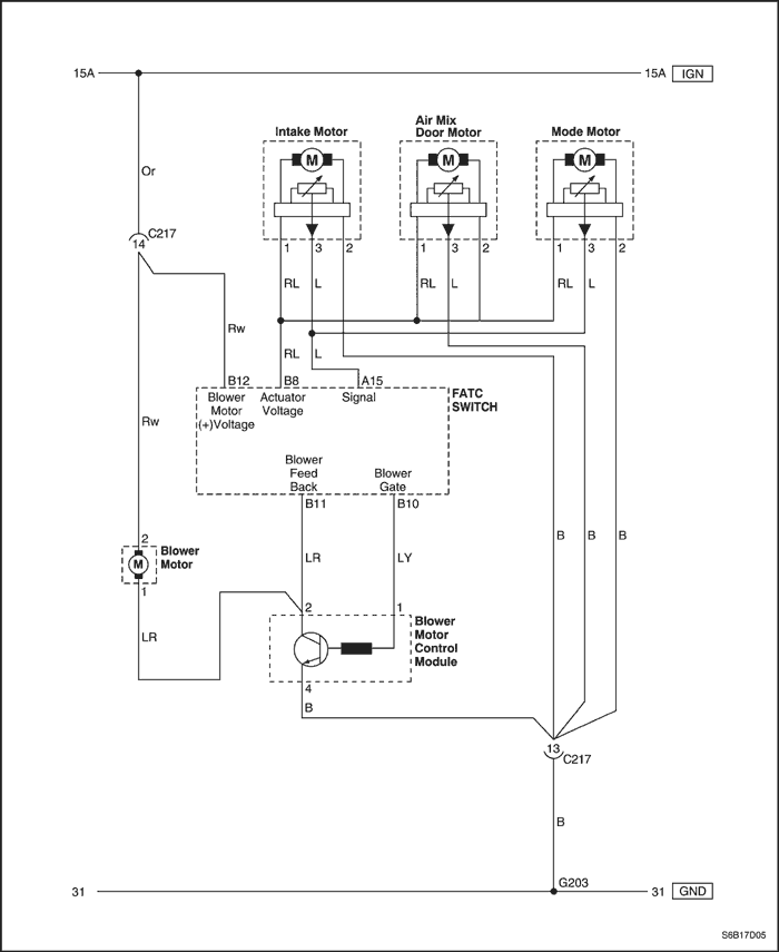
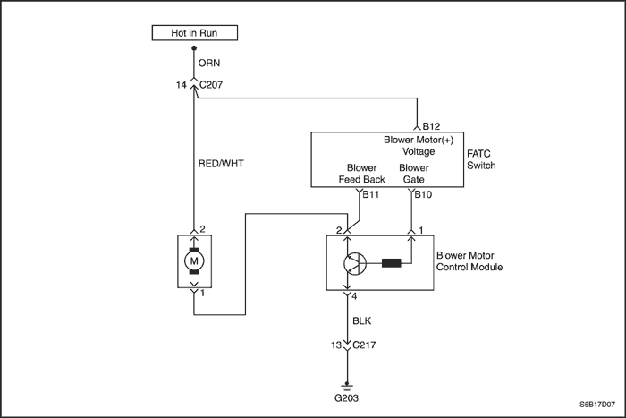
Measure the voltage between ground and terminal B12 (Brown) at the FATC switch.
Is the voltage within the specified value?
|
11-14 v
|
Go to Step 6
|
Go to Step 12
|
| 5 |
Repair any problem found in terminal 2 at the blower motor circuit or ground G203.
Is the repair complete?
|
-
|
System OK
|
-
|
| 6 |
Measure the resistance between the connector terminals on the blower motor.
Does the resistance match the specified value?
|
≈ 5 Ω
|
Go to Step 8
|
Go to Step 7
|
| 7 |
Replace the blower motor.
Is the repair complete?
|
-
|
System OK
|
-
|
| 8 |
Turn the ignition switch to OFF.
Measure the resistance of circuit between terminal 1 of the blower motor and terminal 2, 1 of the power transistor.
Does the resistance match the specified value?
|
≈ 0 Ω
|
Go to Step 10
|
Go to Step 9
|
| 9 |
Repair the problem in circuit.
Is the repair complete?
|
-
|
System OK
|
-
|
| 10 |
Measure the resistance of circuit from terminal 2 of the power transistor connector to ground.
Does the resistance match the specified value?
|
≈ 0 Ω
|
Go to Step 11
|
Go to Step 12
|
| 11 |
Is the repair complete?
|
-
|
System OK
|
-
|
| 12 |
Replace the ATC controller.
the repair complete?
|
-
|
System OK
|
-
|

| Step | Action | Value(s) | Yes | No |
| 1 |
Is there any sign of damage in the wiring or connector, or is the resistance outside the specified value at 25°C (77°F)?
|
2.2KΩ ± 3%
|
Go to Step 2
|
Go to Step 3
|
| 2 |
Repair the damaged wiring or the connector, or replace the in-car sensor as required.
Is the repair complete?
|
-
|
System OK
|
-
|
| 3 |
Is the voltage equal to the value specified at 25°C (77°F)?
|
2.2 v
|
Go to Step 7
|
Go to Step 4
|
| 4 |
Check the terminals on the in-car sensor connector.
Is any problem found with the connector?
|
-
|
Go to Step 5
|
Go to Step 6
|
| 5 |
Repair the connector terminals or replace the in-car sensor or ATC controller as required.
Is the repair complete?
|
-
|
System OK
|
-
|
| 6 |
Does this display indicate the continuing presence of a code 1 condition?
|
-
|
Go to Step 7
|
System OK
|
| 7 |
Replace the ATC controller.
Is the repair complete?
|
-
|
System OK
|
-
|
| Step | Action | Value(s) | Yes | No |
| 1 |
Is the resistance equal to the specified value at 25°C (77°F)?
|
2.2KΩ ± 3%
|
Go to Step 5
|
Go to Step 2
|
| 2 |
Is there a problem with the wiring or the connector?
|
-
|
Go to Step 3
|
Go to Step 4
|
| 3 |
Repair the problem found in the ambient air sensor wiring or the connector.
Is the repair complete?
|
-
|
System OK
|
-
|
| 4 |
Replace the ambient air sensor.
Is the repair complete?
|
-
|
System OK
|
-
|
| 5 |
Is the voltage equal to the value specified at 25°C (77°F)?
|
2.2 v
|
Go to Step 7
|
Go to Step 6
|
| 6 |
Does this display indicate the continuing presence of a code 2 condition?
|
-
|
Go to Step 8
|
System OK
|
| 7 |
Is the voltage equal to the value specified?
|
2.2 v
|
Go to Step 8
|
Go to Step 9
|
| 8 |
Replace the ATC Controller.
Is the repair complete?
|
-
|
System OK
|
-
|
| 9 |
Is the repair complete?
|
-
|
System OK
|
-
|
| Step | Action | Value(s) | Yes | No |
| 1 |
Is there any sign of damage in the wiring or the connector, or is the resistance outside the specified value at 25°C (77°F)?
|
2.2KΩ ± 3%
|
Go to Step 2
|
Go to Step 3
|
| 2 |
Repair the damaged wiring or the connector, or replace the coolant temperature sensor as required.
Is the repair complete?
|
-
|
System OK
|
-
|
| 3 |
Is the voltage equal to the specified value at 40°C (104°F) and 50°C (122°F)?
|
40°C (104°F) → 3.7 v
50°C (122°F) → 2.9 v
|
Go to Step 7
|
Go to Step 4
|
| 4 |
Check the terminals on the coolant temperature sensor connector.
Is any problem found with the connector?
|
-
|
Go to Step 5
|
Go to Step 6
|
| 5 |
Repair the connector terminals or replace the coolant temperature sensor or ATC controller as required.
Is the repair complete?
|
-
|
System OK
|
-
|
| 6 |
Does this display indicate the continuing presence of a code 3 condition?
|
-
|
Go to Step 9
|
System OK
|
| 7 |
Is the voltage equal to the value specified?
|
40°C (104°F) → 3.7 v
50°C (122°F) → 2.9 v
|
Go to Step 9
|
Go to Step 8
|
| 8 |
Is the repair complete?
|
-
|
System OK
|
-
|
| 9 |
Replace the ATC controller.
Is the repair complete?
|
-
|
System OK
|
-
|
| Step | Action | Value(s) | Yes | No |
| 1 |
Does the measured resistance indicate an open or a shorted condition?
|
Open = ∞,
Short = 0 Ω
|
Go to Step 4
|
Go to Step 2
|
| 2 |
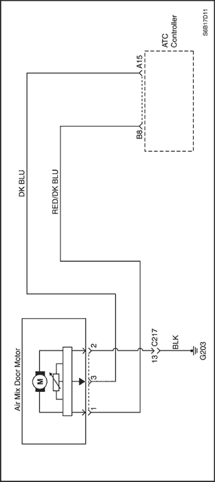
Measure the voltage between terminals 1 and 2 on the AMD motor.
Is the voltage equal to the value specified?
|
13.5 v
|
Go to Step 3
|
Go to Step 4
|
| 3 |
Measure the voltage between terminals 3 of AMD and terminals A15 on the ATC.
Is the voltage equal to the value specified?
|
6.0 ± 0.5 v
|
Go to Step 5
|
Go to Step 4
|
| 4 |
Replace the AMD motor.
Is the repair complete?
|
-
|
System OK
|
-
|
| 5 |
Check the connector terminals at the AMD motor and the wiring in the ATC harness.
Is there a problem with any terminal on either the harness connector or the motor connector or the wiring?
|
-
|
Go to Step 6
|
Go to Step 7
|
| 6 |
Repair the problem found with a connector terminal or the wiring, or replace the motor as required.
Is the repair complete?
|
-
|
System OK
|
-
|
| 7 |
Is there a problem with any of these connectors or the wiring?
|
-
|
Go to Step 8
|
Go to Step 9
|
| 8 |
Repair the problem found with a connector terminal or wiring.
Is the repair complete?
|
-
|
System OK
|
-
|
| 9 |
Check continuity in the harness between the controller connectors and the AMD motor connector.
Does the continuity equal the specified value?
|
≈ 0 Ω
|
Go to Step 10
|
Go to Step 1
|
| 10 |
Repair the continuity problem.
Is the repair complete?
|
-
|
System OK
|
-
|
| Step | Action | Value(s) | Yes | No |
| 1 |
Is there any sign of damage in the wiring or connector or does the resistance equal the value specified?
|
≈ 0 Ω
|
Go to Step 2
|
Go to Step 3
|
| 2 |
Repair the damaged wiring or the connector, or replace the sun sensor as required.
Is the repair complete?
|
-
|
System OK
|
-
|
| 3 |
Is the voltage equal to the specified value?
|
2.5 v ~ 4.8 v
|
Go to Step 7
|
Go to Step 4
|
| 4 |
Check the terminals on the sun sensor connector.
Is any problem found with the connector?
|
-
|
Go to Step 5
|
Go to Step 6
|
| 5 |
Repair the connector terminals or replace the sun sensor or ATC controller as required.
Is the repair complete?
|
-
|
System OK
|
-
|
| 6 |
Does this display indicate the continuing presence of a code 5 condition?
|
-
|
Go to Step 9
|
System OK
|
| 7 |
Is the voltage equal to the value specified?
|
2.5 v ~ 4.8 v
|
Go to Step 9
|
Go to Step 8
|
| 8 |
Is the repair complete?
|
-
|
System OK
|
-
|
| 9 |
Replace the ATC controller.
Is the repair complete?
|
-
|
System OK
|
-
|
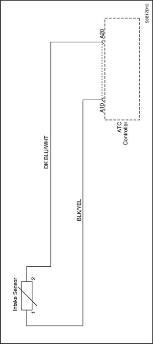
| Step | Action | Value(s) | Yes | No |
| 1 |
Is there any sign of damage in the wiring or connector, or is the resistance outside the specified value at 1°C (33.8°F)?
|
8KΩ ± 1%
|
Go to Step 2
|
Go to Step 3
|
| 2 |
Repair the damaged wiring or the connector, or replace the intake sensor as required.
Is the repair complete?
|
-
|
System OK
|
-
|
| 3 |
Is the voltage equal to the value specified?
|
6 v
|
Go to Step 7
|
Go to Step 4
|
| 4 |
Check the terminals on the intake sensor connector.
Is any problem found with the connector?
|
-
|
Go to Step 5
|
Go to Step 6
|
| 5 |
Repair the connector terminals or replace the intake sensor or ATC controller as required.
Is the repair complete?
|
-
|
System OK
|
-
|

| Step | Action | Value(s) | Yes | No |
| 1 |
Does the measured resistance indicate an open or a shorted condition?
|
Open = ∞,
Short = 0 Ω
|
Go to Step 4
|
Go to Step 2
|
| 2 |
Measure the voltage between terminals 1 and 2 on the AMD motor.
Is the voltage equal to the value specified?
|
13.5 v
|
Go to Step 3
|
Go to Step 4
|
| 3 |
Measure the voltage between terminals 3 of AMD and terminals A15 on the ATC.
Is the voltage equal to the value specified?
|
6.0 ± 0.5 v
|
Go to Step 5
|
Go to Step 4
|
| 4 |
Replace the AMD motor.
Is the repair complete?
|
-
|
System OK
|
-
|
| 5 |
Check the connector terminals at the AMD motor and the wiring in the ATC harness.
Is there a problem with any terminal on either the harness connector or the motor connector or the wiring?
|
-
|
Go to Step 6
|
Go to Step 7
|
| 6 |
Repair the problem found with a connector terminal or the wiring, or replace the motor as required.
Is the repair complete?
|
-
|
System OK
|
-
|
| 7 |
Is there a problem with any of these connectors or the wiring?
|
-
|
Go to Step 8
|
Go to Step 9
|
| 8 |
Repair the problem found with a connector terminal or wiring.
Is the repair complete?
|
-
|
System OK
|
-
|
| 9 |
Check continuity in the harness between the controller connectors and the AMD motor connector.
Does the continuity equal the specified value?
|
≈ 0 Ω
|
Go to Step 10
|
Go to Step 1
|
| 10 |
Repair the continuity problem.
Is the repair complete?
|
-
|
System OK
|
-
|
| © Copyright Chevrolet Europe. All rights reserved |


