Aveo |
||||||||
|
||||||||
Application
|
N•m
|
Lb-Ft
|
Lb-In
|
|
Audio System Screws
|
6
|
-
|
53
|
|
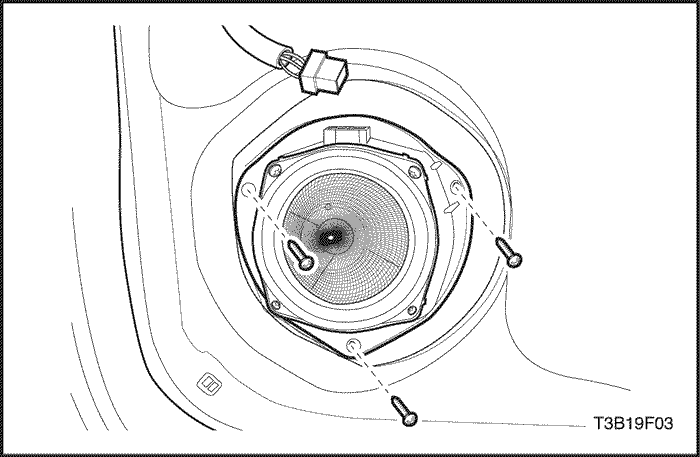
Front Speaker Screws
|
3.5
|
-
|
31
|
|
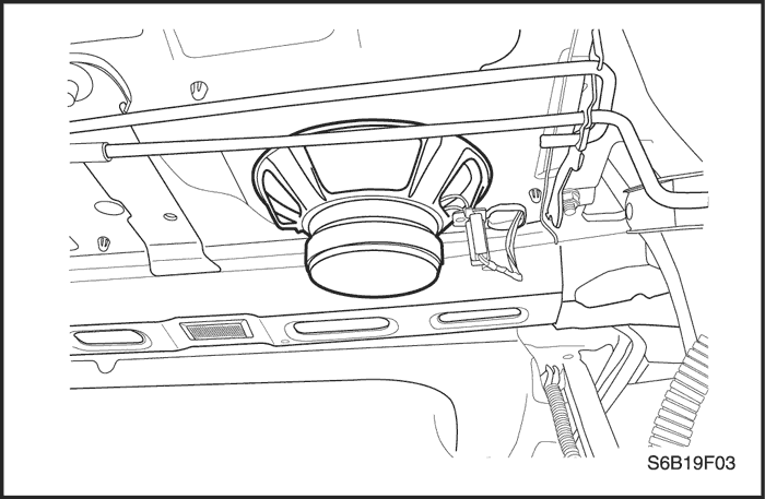
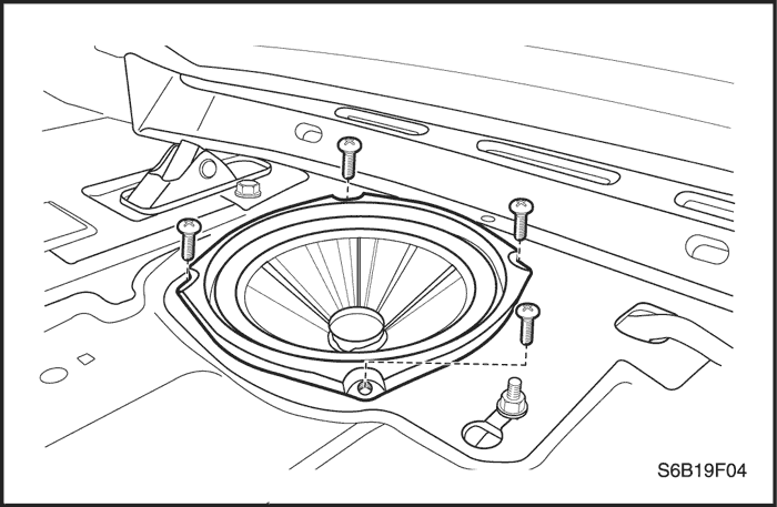
Rear Speaker Screws
|
3
|
-
|
27
|
|
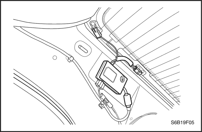
Back Glass Antenna Retaining Screw
|
3
|
-
|
27
|
| Step | Action | Value(s) | Yes | No |
| 1 |
Using a good-quality CD, determine if the CD player performs poorly or is inoperative.
Does the CD player function correctly?
|
-
|
Go to Step 2
|
Go to Step 3
|
| 2 |
Inform the customer that the problem is with the CD, not the CD player.
Has the customer been informed?
|
-
|
System OK
|
-
|
| 3 |
Check the CD player for obstructions behind the tape door.
Is an obstruction found?
|
-
|
Go to Step 4
|
Go to Step 6
|
| 4 |
Check to see if the obstruction can be removed.
Can the obstruction be removed?
|
-
|
Go to Step 5
|
Go to Step 6
|
| 5 |
Remove the obstruction.
Is the repair complete?
|
-
|
System OK
|
-
|
| 6 |
Replace the CD player.
Is the repair complete?
|
-
|
System OK
|
-
|
| Step | Action | Value(s) | Yes | No |
| 1 |
Check fuses F21 and F9.
Are fuses F21 and F9 blown?
|
-
|
Go to Step 2
|
Go to Step 3
|
| 2 |
Is the repair complete?
|
-
|
System OK
|
-
|
| 3 |
Does the battery voltagematch the specified value at fuses F21 and F9?
|
11-14 v
|
Go to Step 5
|
Go to Step 4
|
| 4 |
Repair the power supply circuit to the fuses.
Is the repair complete?
|
-
|
System OK
|
-
|
| 5 |
Does the battery voltage match the specified value at both terminals?
|
11-14 v
|
Go to Step 7
|
Go to Step 6
|
| 6 |
Repair the open circuit between the audio system connector and the fuse.
Is the repair complete?
|
-
|
System OK
|
-
|
| 7 |
Use an ohmmeter to test the ground circuit at the audio system connector terminal A8.
Does the resistancematch the specified value?
|
≈ 0 Ω
|
Go to Step 9
|
Go to Step 8
|
| 8 |
Repair the open ground circuit between the audio system connector and ground G202.
Is the repair complete?
|
-
|
System OK
|
-
|
| 9 |
Replace the cassette radio.
Is the repair complete?
|
-
|
System OK
|
-
|
| Step | Action | Value(s) | Yes | No |
| 1 |
Verify the customer complaint.
Does the cassette player destroy tapes?
|
-
|
Go to Step 5
|
Go to Step 2
|
| 2 |
Using a good-quality tape, determine whether the cassette player performs poorly or is inoperative.
Does the cassette player perform poorly?
|
-
|
Go to Step 5
|
Go to Step 3
|
| 3 |
Check the cassette player for obstructions behind the tape door.
Is an obstruction found?
|
-
|
Go to Step 4
|
Go to Step 8
|
| 4 |
Check to see if the obstruction can be removed using gentle force.
Is the obstruction removed?
|
-
|
Go to Step 5
|
Go to Step 6
|
| 5 |
Clean the cassette player head, the capstan, and the drive system.
Does the tape play properly?
|
-
|
Go to Step 7
|
Go to Step 6
|
| 6 |
Replace the cassette radio.
Is the repair complete?
|
-
|
System OK
|
-
|
| 7 |
Check the cassette player for normal operation.
Is the repair complete?
|
-
|
System OK
|
-
|
| 8 |
Advise the owner of a defective or worn tape.
Is the repair complete?
|
-
|
System OK
|
-
|
| Step | Action | Value(s) | Yes | No |
| 1 |
Check the audio system for normal operation.
Is AM inoperative and the rest of the system operating properly?
|
-
|
Go to Step 2
|
System OK
|
| 2 |
Replace the radio.
Is the repair complete?
|
-
|
System OK
|
-
|
| Step | Action | Value(s) | Yes | No |
| 1 |
Is the FM radio operating properly?
|
-
|
Go to Step 2
|
Go to Step 3
|
| 2 |
Replace the antenna.
Is the repair complete?
|
-
|
System OK
|
-
|
| 3 |
Is the FM radio operating properly?
|
-
|
Go to Step 4
|
Go to Step 5
|
| 4 |
Replace the antenna cable between the audio system and the antenna.
Is the repair complete?
|
-
|
System OK
|
-
|
| 5 |
Replace the cassette radio.
Is the repair complete?
|
-
|
System OK
|
-
|
| Step | Action | Value(s) | Yes | No |
| 1 |
Are the front speakers distorted?
|
-
|
Go to Step 2
|
Go to Step 4
|
| 2 |
Check the speaker and the door area for damage, rattles, or vibration.
Is there anything loose or in the way of the speaker causing the distortion?
|
-
|
Go to Step 3
|
Go to Step 4
|
| 3 |
Make the necessary repairs to secure the component causing the distortion.
Is the repair complete?
|
-
|
System OK
|
-
|
| 4 |
Does the ohmmeter show the specified value?
|
∞
|
Go to Step 6
|
Go to Step 5
|
| 5 |
Repair the short circuit between the front speaker connector and the radio connector.
Is the repair complete?
|
-
|
System OK
|
-
|
| 6 |
Substitute a known good speaker for the speaker causing the distortion.
Is the distortion eliminated?
|
-
|
Go to Step 7
|
Go to Step 8
|
| 7 |
Replace the speaker.
Is the repair complete?
|
-
|
System OK
|
-
|
| 8 |
Replace the cassette radio.
Is the repair complete?
|
-
|
System OK
|
-
|
| Step | Action | Value(s) | Yes | No |
| 1 |
Are the rear speakers distorted?
|
-
|
Go to Step 2
|
Go to Step 4
|
| 2 |
Check the speakers, the rear deck, and the trunk area for damage, rattles, or vibration.
Is there anything loose or in the way of the speaker causing the distortion?
|
-
|
Go to Step 3
|
Go to Step 4
|
| 3 |
Make the necessary repairs to secure the component causing the distortion.
Is the repair complete?
|
-
|
System OK
|
-
|
| 4 |
Does the ohmmeter show the specified value?
|
∞
|
Go to Step 6
|
Go to Step 5
|
| 5 |
Repair the short circuit between the rear speaker connector and the radio connector.
Is the repair complete?
|
-
|
System OK
|
-
|
| 6 |
Substitute a known good speaker for the speaker causing the distortion.
Is the distortion eliminated?
|
-
|
Go to Step 7
|
Go to Step 8
|
| 7 |
Replace the speaker.
Is the repair complete?
|
-
|
System OK
|
-
|
| 8 |
Replace the audio system.
Is the repair complete?
|
-
|
System OK
|
-
|
| © Copyright Chevrolet Europe. All rights reserved |


