Engine Front Cover and Oil Pump Installation
Special Tools
| • | EN-49977-100 Transmitter Disc Fixation |
| • | EN-49977-200 Fixing Tool |
For equivalent regional tools, refer to Special Tools .
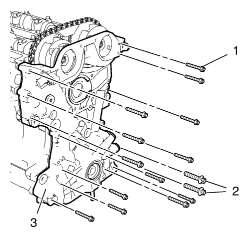
Note: Mind the guide sleeves when installing engine front cover.
- Install the engine front cover (3).
- Install the 13 engine front cover bolts M6 (1).
- Install the 2 engine front cover bolts M10 (2).
Caution: Refer to Fastener Caution in the Preface section.
- Tighten the 13 engine front cover bolts M6 to 8 N·m (71 lb in).
- Tighten the 2 engine front cover bolts M10 to 35 N·m (26 lb ft).
Camshaft Sprocket Fastening
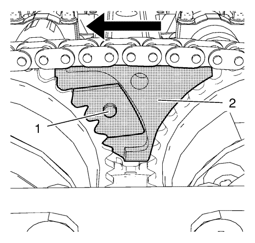
Note: Push the fixing tool in the direction of the arrow to ensure it fully engages.
- Install EN-49977-200 fixing tool (2) and ensure that the gearing of the fixing tool engages with the inlet camshaft sprocket gearing (1).
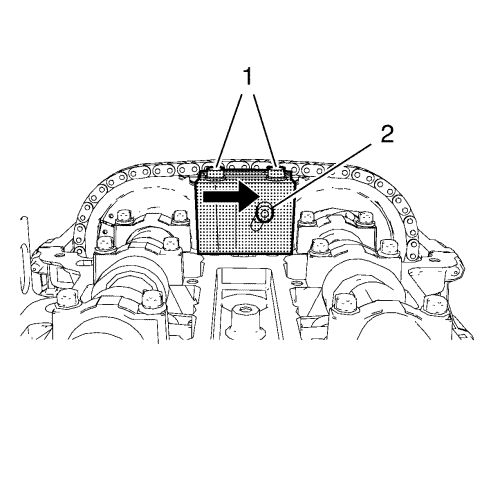
- Tighten the 2 fastening bolts (1) of EN-49977-200 fixing tool while pushing the fixing tool in direction of the arrow.
- Tighten the adjuster bolt (2).
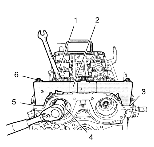
Note: A wrong installation position is possible. Make sure that the holding tool is fully installed to the cylinder head in areas (3) and (5).
- Install EN-49977-100 transmitter disc holder (2) to find and hold the correct position of the camshaft position exciter wheels.
- Tighten the fastening bolts (6) of EN-49977-100 transmitter disc holder .
Caution: Refer to Fastener Caution in the Preface section.
Caution: Refer to Torque-to-Yield Fastener Caution in the Preface section.
- Tighten the NEW intake camshaft sprocket bolt (4) while holding the hexagon (1) of the intake camshaft to 50 N·m (37 lb ft).
- Tighten the inlet camshaft sprocket bolt (4) while holding the hexagon (1) of the inlet camshaft to an additional 60°.
- Tighten the NEW exhaust camshaft sprocket bolt while holding the hexagon of the exhaust camshaft to 50 N·m (37 lb ft).
- Tighten the exhaust camshaft sprocket bolt while holding the hexagon of the exhaust camshaft to an additional 60°.
- Remove EN-49977-100 transmitter disc holder and EN-49977-200 fixing tool .
Upper Timing Chain Guide Installation
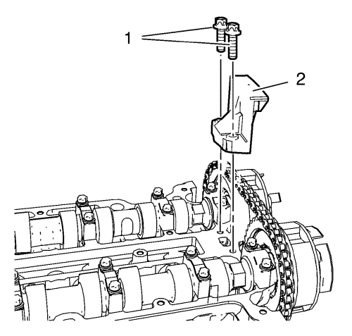
- Install the upper timing chain guide (2).
- Install the 2 upper timing chain guide bolts (1) and tighten to 8 N·m (71 lb in).
- Remove EN-953-A fixing tool and EN-952 fixing pin.
- Install crankshaft bearing cap tie plate hole plug and seal ring and tighten to 40 N·m (30 lb ft).
| © Copyright Chevrolet. All rights reserved |


