Cylinder Head Replacement
Special Tools
| • | EN-50437 Height Gauge - Piston TDC |
For equivalent regional tools, refer to Special Tools .
Removal Procedure
- Remove the inlet manifold bracket . Refer to Inlet Manifold Bracket Replacement
- Remove the exhaust gas recirculation manifold cooling return hose from the thermostat bypass pipe. Refer to
Exhaust Gas Recirculation Manifold Cooling Return Hose Replacement : 2.0L Diesel LNP
- Remove the oil level indicator tube. Refer to Oil Level Indicator Tube Replacement
- Remove the turbocharger. Refer to Turbocharger Replacement
- Remove the charge air cooler outlet hose from the throttle body module. Refer to
Charge Air Cooler Outlet Hose Replacement : LNP and Manual Transmission → LNP and Automatic Transmission
- Remove the engine water outlet adaptor. Refer to
Engine Water Outlet Adaptor Replacement : 2.0L Diesel LNP
- Remove the inlet camshaft. Refer to Inlet Camshaft Replacement .

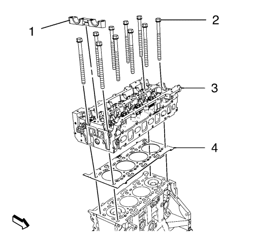
- Remove the camshaft seat guide (1).

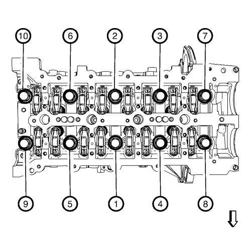
- Loosen the 10 cylinder head retaining bolts in sequence as shown.

- Remove and DISCARD 10 cylinder head retaining bolts (2).
- Remove the cylinder head (3) and the gasket (4).
- Remove the intake manifold. Refer to Inlet Manifold Replacement
- Remove the exhaust manifold. Refer to
Exhaust Manifold Replacement : 2.0L Diesel LNP → 1.6L LDE, LXV, 1.8L 2H0, LUW and LFH
- Remove the hydraulic valve adjusters. Refer to Hydraulic Valve clearance Adjuster Replacement
Cleaning Procedure
Note: Ensure that the cylinder head and the cylinder block sealing surfaces are clear of oil, grease and old gasket material.
- Clean the sealing surfaces.
- Inspect the flatness of cylinder head and cylinder block sealing surfaces.
- Clean the piston surfaces.
Choose the Gasket

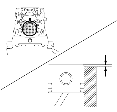
- Align TDC of piston 1.
- Measure the piston projection thickness using EN-50437 height gauge .
- Repeat the measuring process on cylinders 2, 3, 4 and average the measured piston projection values.
- Choose the cylinder head gasket through below the specifications. Refer to Engine Mechanical Specifications .
Installation Procedure
- Install the hydraulic valve lash adjusters. Refer to Hydraulic Valve clearance Adjuster Replacement
- Install the inlet manifold. Refer to Inlet Manifold Replacement
- Install the exhaust manifold. Refer to
Exhaust Manifold Replacement : 2.0L Diesel LNP → 1.6L LDE, LXV, 1.8L 2H0, LUW and LFH

- Clean the sealing surfaces.
- Install the cylinder head (3) and a NEW gasket (4).
Note: Do not tighten the bolts.
- Install 10 NEW cylinder head retaining bolts (2).
Caution: Refer to Fastener Caution in the Preface section.
Caution: Refer to Torque-to-Yield Fastener Caution in the Preface section.

- Tighten the cylinder head retaining bolts (2) in four steps, in a sequence as shown in the illustration above:
| • | First step 30 N·m (22 lb ft). |
| • | Second step 100 N·m (74 lb ft). |
| • | Third step 90°. Use EN-470-B angle meter . |
| • | Fourth step 90°. Use EN-470-B angle meter . |

- Install the camshaft seat guide (1).
- Install the inlet camshaft. Refer to Inlet Camshaft Replacement .
- Install the engine water outlet adaptor. Refer to
Engine Water Outlet Adaptor Replacement : 2.0L Diesel LNP
- Install the charge air cooler outlet hose to the throttle body module. Refer to
Charge Air Cooler Outlet Hose Replacement : LNP and Manual Transmission → LNP and Automatic Transmission
- Install the turbocharger. Refer to Turbocharger Replacement
- Install the oil level indicator tube. Refer to Oil Level Indicator Tube Replacement
- Install the exhaust gas recirculation manifold cooling return hose to the thermostat bypass pipe. Refer to
Exhaust Gas Recirculation Manifold Cooling Return Hose Replacement : 2.0L Diesel LNP
- Install the inlet manifold bracket . Refer to Inlet Manifold Bracket Replacement
| © Copyright Chevrolet. All rights reserved |
| © Copyright Chevrolet. All rights reserved |


