Engine Replacement - Automatic Transmission
Special Tools
| • | EN-796-A Remover Quick Fitting |
| • | CH-49290 Mounting Engine / Transmission |
| • | CH-49289 Centring Adapter |
| • | EN-50057 Engine Overhaul Stand |
For equivalent regional tools, refer to Special Tools .
Removal Procedure
- Remove the lower intermediate steering shaft bolt. Refer to Intermediate Steering Shaft Replacement .
- Open the bonnet.
- Remove the engine sight shield. Refer to Engine Sight Shield Replacement .
- Recover the refrigerant. Refer to Refrigerant Recovery and Recharging .
- Remove the battery tray. Refer to Battery Tray Replacement
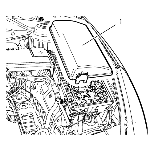
- Remove the front compartment fuse block cover (1).
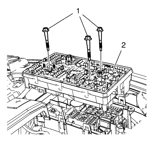
- Remove the 3 front compartment fuse block bolts (1).
- Remove the front compartment fuse block (2).
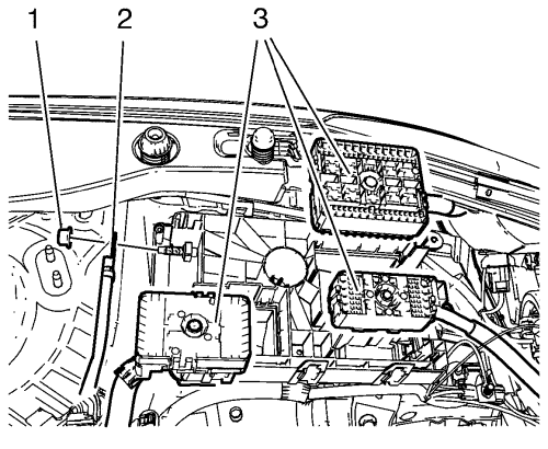
- Unclip the 3 wiring harness plugs (3).
- Disconnect the wiring harness plug from the front compartment fuse block.
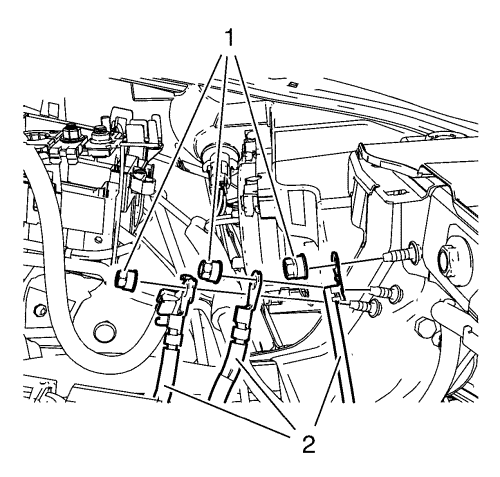
- Remove the 3 ground nuts (1) and put the 4 wiring harness (2) aside.
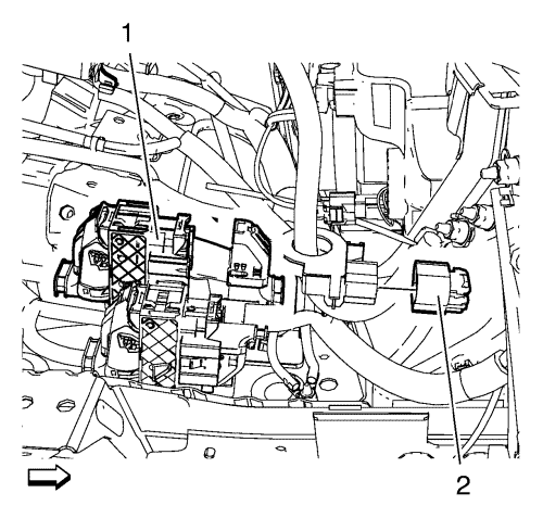
- Disconnect the 2 wiring harness plugs (1, 2).
- Remove the air cleaner assembly. Refer to Air Cleaner Assembly Replacement .
- Remove the front bumper fascia. Refer to Front Bumper Fascia Removal and Installation .
- Remove the front tyre and wheel assembly. Refer to Tyre and Wheel Removal and Installation .
- Drain the cooling system. Refer to Cooling System Draining and Filling .
- Unclip the radiator surge tank.
- Put the radiator surge tank aside.
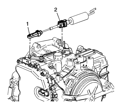
- Disconnect the transmission range selector lever cable terminal (1) from the transmission manual gear lever pin.
- Press the locking tabs inward in order to release the transmission range selector lever cable (2) from the cable bracket.
- Remove the heater inlet hose from the bulkhead. Refer to
Heater Inlet Hose Replacement : 2.0L Diesel LNP → 1.8L 2H0 and LFH .
- Remove the heater outlet hose from the bulkhead. Refer to
Heater Outlet Hose Replacement : 2.0L Diesel LNP → 1.8L 2H0 and LFH .
- Remove power steering fluid reservoir bolt.
- Unclip power steering fluid reservoir and support it on the engine.
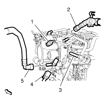
- Disconnect the fuel injection pump wiring harness plug (4).
- Disconnect the fuel feed front pipe (5) and unclip from the fuel return front pipe clip. Refer to Plastic Collar Quick Connect Fitting Service .
- Close the fuel feed front pipe (5) with the EN-6015 closure plugs .
- Disconnect the fuel return front pipe (2), using the EN-796-A remover . Refer to Plastic Collar Quick Connect Fitting Service .
- Close the fuel injection fuel return pipe with the CH-807 closure plugs .
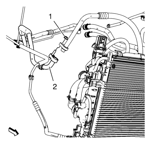
- Remove A/C compressor and condenser hose nut (1) from refrigerant hose (2).
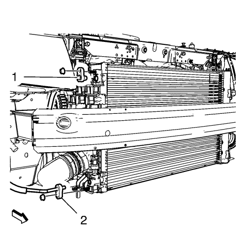
- Remove the lower and upper condenser hose nuts and the lower and upper condenser hoses (1,2).
- Remove the exhaust front pipe. Refer to
Exhaust Front Pipe Replacement : 2.0L Diesel LNP → LDE, LLU, LXT, LXV, L2W, 2H0, LFH,LGE .
- Remove the upper stabiliser shaft link from the absorber on both sides. Refer to Stabilizer Shaft Link Replacement .
- Remove steering linkage outer track rod from the steering knuckle on both sides. Refer to Steering Linkage Outer Track rod Replacement .
- Remove the front lower control arm from the steering knuckle. Refer to Lower Control Arm Replacement .
- Remove the front wheel shafts from the wheel hubs. Refer to Front Wheel Drive Shaft Replacement - Right Side .
- Remove the wheel speed sensor wiring harness (2) from the frame on both sides.
- Remove the wiring harness retainers (3) from the frame and the lower control arm.
- Remove the wiring harness retainers (3) from the frame and the lower control arm.
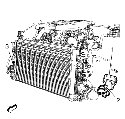
- Remove wiring harness engine cooling fan.
| • | Disconnect the 4 wiring harness connector engine cooling fan (2). |
| • | Remove engine coolant fan wiring harness relay block (1). |
| • | Disconnect wiring harness connector air conditioning refrigerant pressure sensor (3). |
Note: The SPX installation manual is supplied with the special tool and is also available online from SPX directly. Go to www.spxtools-shop.com.
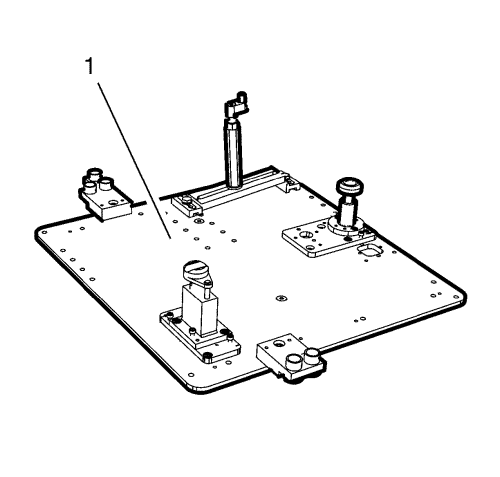
- Assemble the CH-49290 engine support tool (1) according to the details provided in the SPX installation manual.
- Support the CH-904 base frame on a jack.
- Support the CH-49290 engine support tool on the CH-904 base frame .
Note: The SPX installation manual is supplied with the special tool and is also available online from SPX directly. Go to www.spxtools-shop.com.
- Install the CH-49290 engine support tool (1) according to the details provided in the SPX installation manual.
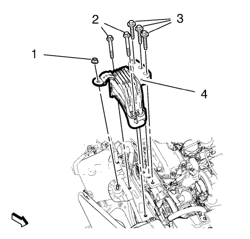
- Remove the 5 engine mount bracket retaining bolts (2, 3) and the engine mount retaining nut (1).
- Remove the engine mount (4).
- Remove the transmission mount - left side. Refer to Transmission Mount Replacement - Left Side .
Note: The SPX installation manual is supplied with the special tool and is also available online from SPX directly. Go to www.spxtools-shop.com.
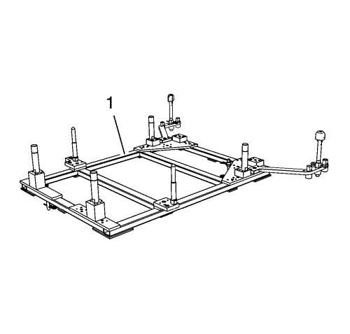
- Assemble the CH-49289 centring frame (1) according to the details provided in the SPX installation manual.
- Support the CH-904 base frame on a jack.
- Support the CH-49289 centring frame on the CH-904 base frame .
Note: The SPX installation manual is supplied with the special tool and is also available online from SPX directly. Go to www.spxtools-shop.com.
- Install the CH-49289 centring frame (1) according to the details provided in the SPX installation manual.
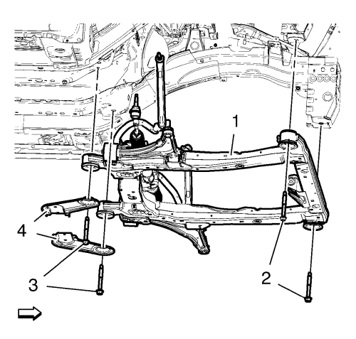
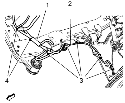
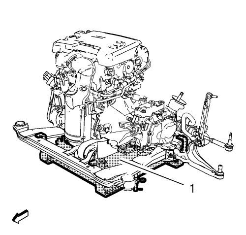
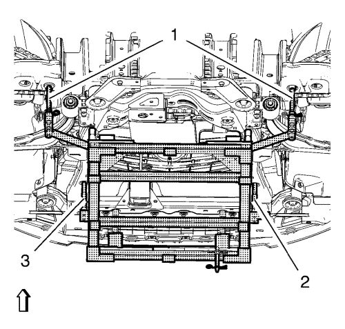
Note: Simplified graphic. Engine/transmission unit is fixed with engine support tool to suspension frame. Suspension frame is supported by centring adapter and underframe.
- Remove the front frame bolts (2).
- Remove the rear frame bolts (3).
- Remove the frame reinforcements (4).
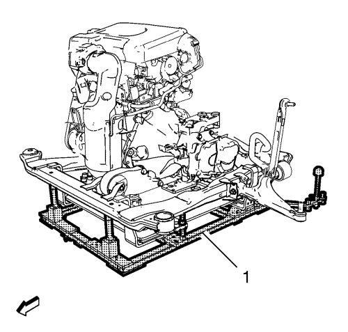
- Lower the frame (1) with the engine transmission unit from the vehicle.
- Remove the right wheel drive shaft from the transmission. Refer to Front Wheel Drive Shaft Replacement - Right Side .
- Remove the left wheel drive shaft from the transmission. Refer to Front Wheel Drive Shaft Replacement - Left Side .
- Install suitable cable at the 3 engine lift brackets.
- Install a suitable engine lifting device to the cable.
- Extend the engine lifting device until the steel cable are slightly tensioned.
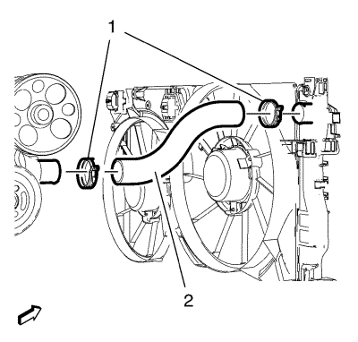
- Loosen the radiator outlet hose clip (1) from radiator.
- Remove the radiator outlet hose (2) from the radiator.
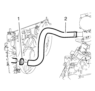
- Loosen the radiator inlet hose clip (1).
- Remove the radiator inlet hose (2) from the radiator.
- Remove the transmission fluid cooler inlet pipe. Refer to
Transmission Fluid Cooler Inlet Pipe Replacement : LBN, LLW
- Remove the transmission fluid cooler outlet pipe. Refer to
Transmission Fluid Cooler Outlet Pipe Replacement : LBN, LLW
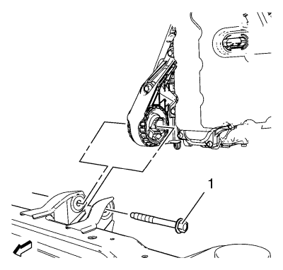
- Remove the front transaxle mount through bolt (1).
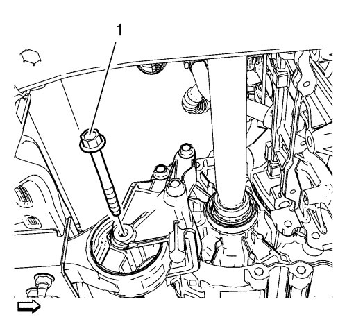
- Remove the transmission bracket mount to mount through bolt (1).
- Put the engine transmission unit down on a wooden pallet.
- Loosen the 9 transmission bolts and remove 8 of them. Refer to
Transmission Replacement : 2.0L Diesel LNP → 1.6L LXT, L2W, LDE and 1.8L 2H0 .
Note: 2nd mechanic required.
- Remove the last transmission bolt and the transmission.
- Install the engine to the EN-50057 engine stand .
- Transfer parts as needed.
Installation Procedure
- Remove the engine from the EN-50057 engine stand.
- Put the engine down on a wooden pallet.
Note: Second mechanic required.
- Install the transmission and one transmission bolt.
- Install the 8 transmission bolts.
Caution: Refer to Fastener Caution in the Preface section.
- Tighten the 9 transmission bolts. Refer to
Transmission Replacement : 2.0L Diesel LNP → 1.6L LXT, L2W, LDE and 1.8L 2H0 .
- Place the engine transmission unit on to the front suspension frame.
- Install the transmission bracket mount to mount through bolt (1) and tighten to 100 N·m(74 lb ft).
- Install the transaxle mount through bolt (1) and tighten to 58 N·m (43 lb ft).
- Remove the cable from the 3 engine lift brackets.
- Install the transmission fluid cooler inlet pipe. Refer to
Transmission Fluid Cooler Inlet Pipe Replacement : LBN, LLW .
- Install the transmission fluid cooler outlet pipe. Refer to
Transmission Fluid Cooler Outlet Pipe Replacement : LBN, LLW .
- Install the radiator inlet hose (2) to the radiator .
- Install the radiator inlet hose clamp (1).
- Install the radiator outlet hose (2) to the radiator.
- Install the radiator outlet hose clamp (1).
- Install the left wheel drive shaft to the transmission. Refer to Front Wheel Drive Shaft Replacement - Left Side .
- Install the right wheel drive shaft to the transmission. Refer to Front Wheel Drive Shaft Replacement - Right Side .
Note: Positioning pins (1) of CH-49289 adapter MUST be extended in order to guide into underbody holes.
- Position the frame with the engine transmission unit to the vehicle.
- Install the frame reinforcements (3).
- Install frame rear bolts (2). Handtighten ONLY.
- Install frame front bolts (3). Handtighten ONLY.
- Tighten the rear frame bolts (2) and tighten to 160N·m (118 lb ft).
- Tighten the front frame bolts (1) and tighten to 160N·m (118 lb ft).
- Lower the CH-49289 centring frame (1) with CH-904 base frame and a jack.
- Remove the CH-49289 centring frame from the CH-904 base frame .
Note: The SPX installation manual is supplied with the special tool and is also available online from SPX directly. Go to www.spxtools-shop.com.
- Disassemble the CH-49289 centring frame (1) according to the details provided in the SPX installation manual.
- Install the engine mount bracket (4).
- Install the 3 engine mount retaining bolts (3). Do not tighten the bolts.
Caution: Refer to Fastener Caution in the Preface section.
- Install the 2 engine mount retaining bolts (2) and the retaining nut (1).
| • | Tighten the bolts (2) to 58 N·m (43 lb ft). |
| • | Tighten the nut (1) to 62 N·m (46 lb ft). |
| • | Tighten the bolts (3) to 58 N·m (43 lb ft). |
- Install the transmission mount - left side. Refer to Transmission Mount Replacement - Left Side .
- Lower the CH-49290 engine support tool (1) with CH-904 base frame and a jack.
- Remove the CH-49290 engine support tool from the CH-904 base frame .
Note: The SPX installation manual is supplied with the special tool and is also available online from SPX directly. Go to www.spxtools-shop.com.
- Disassemble the CH-49290 engine support tool (1) according to the details provided in the SPX installation manual.
- Install the exhaust front pipe. Refer to
Exhaust Front Pipe Replacement : 2.0L Diesel LNP → LDE, LLU, LXT, LXV, L2W, 2H0, LFH,LGE .
- Install wiring harness engine cooling fan.
| • | Connect wiring harness connector air conditioning refrigerant pressure sensor (3). |
| • | Install engine coolant fan wiring harness relay block (1). |
| • | Connect the 4 harness connector engine cooling fan (2). |
- Install the wheel speed sensor wiring harness (2) to the frame on both sides.
Install the wiring harness retainers (3) to the frame and the lower control arm.
- Lower the vehicle.
- Install the front wheel shafts to the wheel hubs. Refer to Front Wheel Drive Shaft Replacement - Right Side .
- Install the front lower control arm to the steering knuckle. Refer to Lower Control Arm Replacement .
- Install the steering linkage outer track rod to the steering knuckle on both sides. Refer to Steering Linkage Outer Track rod Replacement .
- Install the upper stabiliser shaft link to the absorber on both sides. Refer to Stabilizer Shaft Link Replacement .
- Raise the vehicle.
Note: Use a NEW O-ring seal. Refer to Air Conditioning O-Ring Seal Replacement .
- Install the lower and upper condenser hose nuts and the lower and upper condenser hoses (1, 2) and tighten to 19 N·m (14 lb ft).
Note: Use a NEW O-ring seal. Refer to Air Conditioning O-Ring Seal Replacement .
- Install A/C compressor and condenser hose nut (1) to refrigerant hose (2) and tighten to 19 N·m (14 lb ft).
- Remove the CH-807 closure plugs from the fuel injection fuel feed pipe (1).
- Remove the EN-6015 closure plugs from the fuel return front pipe (2).
- Connect the fuel return front pipe (2). Refer to Plastic Collar Quick Connect Fitting Service .
- Connect the fuel feed front pipe (5) and clip to the fuel return front pipe clip. Refer to Plastic Collar Quick Connect Fitting Service .
- Connect the fuel injection pump wiring harness plug (4).
- Clip in the power steering fluid reservoir.
- Install the power steering fluid reservoir bolt and tighten to 9 N·m (80 lb in).
- Install the heater inlet hose to the bulkhead. Refer to
Heater Inlet Hose Replacement : 2.0L Diesel LNP → 1.8L 2H0 and LFH .
- Install the heater outlet hose to the bulkhead. Refer to
Heater Outlet Hose Replacement : 2.0L Diesel LNP → 1.8L 2H0 and LFH .
- Install the transmission range selector lever cable (2) to the cable bracket.
- Connect the transmission range selector lever cable terminal (1) to the transmission manual gear lever pin.
- Check the range selector cable adjustment. Refer to Range Selector Lever Cable Adjustment .
- Clip in the radiator surge tank.
- Fill the cooling system. Refer to Cooling System Draining and Filling .
- Install the front tyre and wheel assembly. Refer to Tyre and Wheel Removal and Installation .
- Install the front bumper fascia. Refer to Front Bumper Fascia Removal and Installation .
- Install the air cleaner housing. Refer to Air Cleaner Assembly Replacement
- Connect the 2 wiring harness plugs (1, 2).
- Install the 4 wiring harness (2).
- Install the 3 ground nuts (1) and tighten to 9 N·m (80 lb in).
- Clip in the 3 wiring harness plugs (3).
- Connect the wiring harness plug to the front compartment fuse block.
- Install the front compartment fuse block (2).
- Install the 3 front compartment fuse block bolts (1) and tighten to 22 N·m (16 lb ft).
- Install the front compartment fuse block cover (1).
- Fill the transmission with fluid. Refer to Transmission Fluid Level and Condition Check .
- Install the battery tray. Refer to Battery Tray Replacement .
- Install the air cleaner assembly. Refer to Air Cleaner Assembly Replacement .
- Install the engine sight shield. Refer to Engine Sight Shield Replacement .
- Evacuate and charge the refrigerant system. Refer to Refrigerant Recovery and Recharging .
- Check the oil level and fill NEW engine oil up if necessary.
- Refill the cooling system. Refer to Cooling System Draining and Filling .
- Close the bonnet.
- Install the lower intermediate steering shaft bolt. Refer to Intermediate Steering Shaft Replacement
| © Copyright Chevrolet. All rights reserved |
| © Copyright Chevrolet. All rights reserved |


