Engine Compression Test
Special Tools
| • | EN-50453 Adaptor - Air Compression |
| • | EN-50454 Gauge - Cylinder Pressure |
For equivalent regional tools, refer to Special Tools .
Removal Procedure
- Remove the engine sight shield. Refer to Engine Sight Shield Replacement .
- Disconnect the battery negative cable. Refer to
Battery Negative Cable Disconnection and Connection : without Start/Stop System .
- Remove the 4 fuel injection fuel feed pipes . Refer to Fuel Injection Fuel Feed Pipe Removal .
- Remove the 4 fuel injectors . Refer to Fuel Injector Removal .

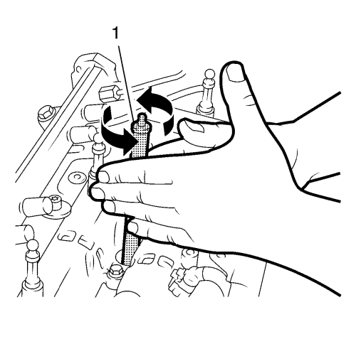
- Clean the injector sealing surfaces in the cylinder head using the EN-47632 cleaning tool (1) in following procedure:
| 5.1. | Use the brush side to loosen the dirt. |
| 5.2. | Use the sponge side to remove the dirt. |

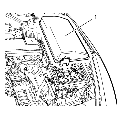
- Remove the front compartment fuse block cover (1).
- Remove the fuel pump relay.
Compression Test Cylinder 1 - 4

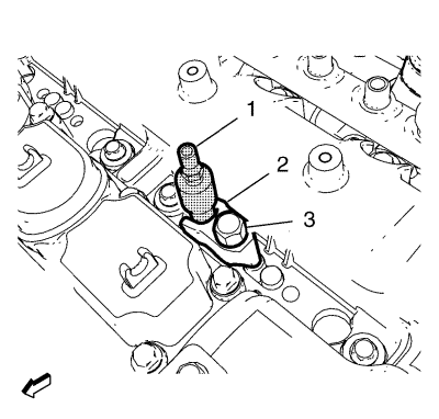
- Install EN-50453 adaptor (1) to cylinder 1.
- Install the fuel injector bracket (2).
Caution: Refer to Fastener Caution in the Preface section.
- Install fuel injector bracket bolt (3) and tighten to 14 N·m+110° (124 lb in) +110°.

Note: Use a gauge with a measuring range of 10-40 bar (145-580 PSI).
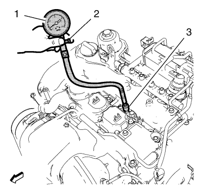
- Install the EN-50454 gauge (1) to the EN-50453 adaptor (3).
- Connect the battery negative cable. Refer to
Battery Negative Cable Disconnection and Connection : without Start/Stop System .
- Check the compression of cylinder 1.
Note: A second technician is required.
- Start engine for approximately 4 seconds.
Note: Engine speed at least 200 RPM.
- Note the compression value.
- Disconnect the battery negative cable. Refer to
Battery Negative Cable Disconnection and Connection : without Start/Stop System .
- Release pressure from the EN-50454 gauge (1) by pushing the release button (2).
- Remove the EN-50454 gauge (1) from the EN-50453 adaptor .

- Remove the fuel injector bracket bolt (3).
- Remove the fuel injector bracket (2).
- Remove the EN-46791 adaptor (1) from cylinder 1.
- Repeat steps 1 to 13 to determine the compression of cylinders 2, 3, 4.
Installation Procedure
- Install the 4 fuel injectors . Refer to Fuel Injector Installation .
- Install the 4 fuel injection fuel feed pipes. Refer to Fuel Injection Fuel Feed Pipe Installation .

- Install the fuel pump relay.
- Install the front compartment fuse block cover (1).
- Connect the battery negative cable. Refer to
Battery Negative Cable Disconnection and Connection : without Start/Stop System .
- Install the engine sight shield. Refer to Engine Sight Shield Replacement .
| © Copyright Chevrolet. All rights reserved |
| © Copyright Chevrolet. All rights reserved |


