To the top of the document
Spark
   
GMDE Start Page Load static TOC Load dynamic TOC Help?

Cylinder Head Cleaning and Inspection

Special Tools

    • EN-6216 Gauge
    • EN-6216-200/300/400 Gauge Instruments
    • EN-301 Gauge Bar
    • GE-571-B Gauge

For equivalent regional tools, refer to Special Tools .

Cleaning Procedure

  1. Remove any old thread sealant, gasket material or sealant.
  2. Clean all cylinder head surfaces with non-corrosive cleanser or tool.
  3. Warning: Refer to Safety Glasses Warning in the Preface section.

  4. Blow out all the oil galleries using compressed air.
  5. Remove any carbon deposits from the combustion chamber.

Visual Inspection

  1. Inspect the cylinder head camshaft bearing surfaces for the following conditions:
  2. • Excessive scoring or pitting
    • Discolouration from overheating
    • Deformation from excessive wear
    • If the camshaft bearing journals appear to be scored or damaged, you must replace the cylinder head. DO NOT machine the camshaft bearing journals.
  3. If any of the above conditions exist on the camshaft bearing surfaces, replace the cylinder head.
  4. Inspect the cylinder head for the following:
  5. • Cracks, damage or pitting in the combustion chambers.
    • Swarf in the oil galleries -- Continue to clean the galleries until all swarf is removed.
    • Coolant leaks or damage to the deck face sealing surface -- If coolant leaks are present, measure the surface warpage as described under cylinder head measurement - deck flatness inspection.
    • Damage to any gasket surfaces.
    • Burnt or eroded areas in the combustion chamber.
    • Cracks in the exhaust ports and combustion chambers.
    • External cracks in the water passages.
    • Restrictions in the inlet or exhaust passages.
    • Restrictions in the cooling system passages.
    • Rusted, damaged or leaking core plugs.
  6. If the cylinder head is cracked or damaged, it must be replaced. No welding or patching of the cylinder head is allowed.

Valve Inspection And Measurement


    2189690
  1. Clean the valves of carbon and oil. Carbon can be removed with a wire brush.
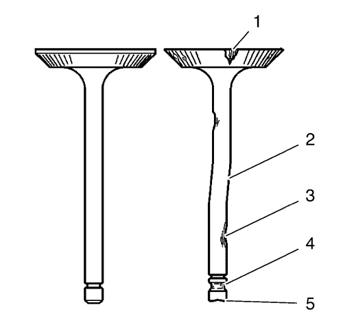
  2. Inspect the valves for the following conditions:
  3. 2.1. Inspect the valve faces for burning and cracking (1). If pieces are broken, replace the valve and inspect the corresponding piston and cylinder head area for damage.
    2.2. Inspect the valve for straightness and distortion (2). Distorted valve must be replaced.
    2.3. Inspect the valve stem for wear (3).
    2.4. Inspect the valve key grooves for chipping and wear (5). Replace the valve if chipped or worn.

    2189668
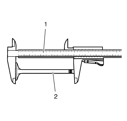
  4. Measure the valve length (2). Use a slide gauge (1). Refer to Engine Mechanical Specifications to find the permitted values. Note the measurement results.

  5. 2189667
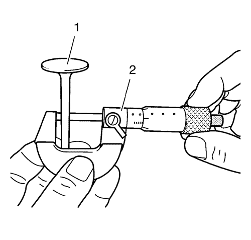
  6. Measure the valve stem diameter. Use a micrometer gauge (2). Refer to Engine Mechanical Specifications to find the permitted values. Note the measurement results.

Cylinder Head Measurement


    2189666
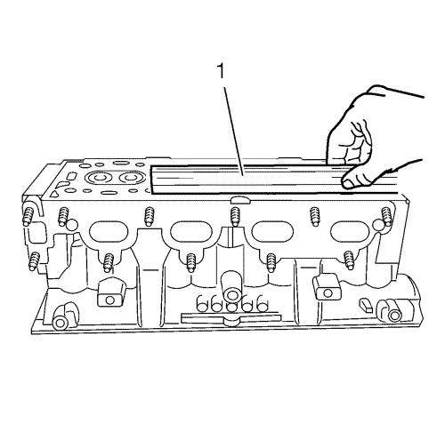
  1. Inspect the cylinder head sealing surface for flatness. Use a straightedge (1).

  2. 2189672
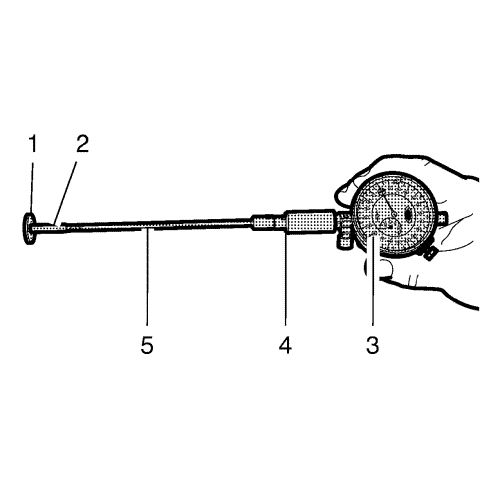
  3. Prepare the gauge for valve stem to guide clearance measurement. Assemble the EN-6216 gauge and the EN-6216-200/300/400 gauge instruments as follows:
  4. 2.1. Install the extension (5) to the support (4).
    2.2. Install the inside calliper (2) to the extension (5).
    2.3. Install the gauge (3) to the support (4) and pretension to 1 mm (0.0394 in).
    2.4. Install the calibration washer (1) as shown to justify the gauge.
    2.5. Adjust the gauge to 0 mm (0 in) by rotating the instrument dial.
    2.6. Carefully remove the calibration washer (1).

    2189673
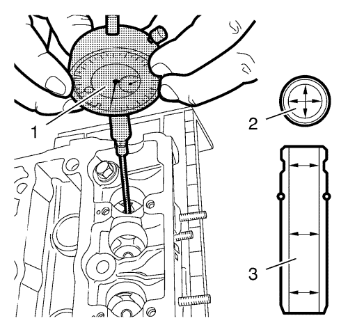
  5. Measure the valve guide inner diameter (2) as shown in different areas (3). Use EN-6216 Gauge (1) and gauge instruments. Note the measurement results. Refer to Engine Mechanical Specifications to find the permitted values. Note the measurement results.
  6. Subtract the valve stem diameter from valve guide inner diameter to calculate the valve stem to guide clearance. Refer to Engine Mechanical Specifications to find the permitted values. Note the measurement results.
  7. Turn the cylinder head upside down.

  8. 2189670
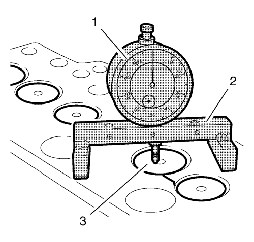
  9. Loosely install one valve to the cylinder head (3).
  10. Place EN-301 gauge bar (2) to the cylinder head sealing surface.
  11. Install EN-571-B gauge to EN-301 gauge bar and measure the valve assembly height. Refer to Engine Mechanical Specifications to find the permitted values. Note the measurement results.


© Copyright Chevrolet. All rights reserved