Mode Control Cam Replacement
Removal Procedure
Note: The left-hand drive is shown. The right-hand drive is similar.
- Remove the driver knee bolster. Refer to
Driver Knee Bolster Replacement : Long Body → Short Body .
- Remove the communication interface module, if equipped. Refer to Communication Interface Module Replacement .
- Disconnect the electrical connector from the mode actuator.
- Remove the mode actuator screws from the evaporator case assembly.
- Remove the mode actuator from the evaporator case assembly.
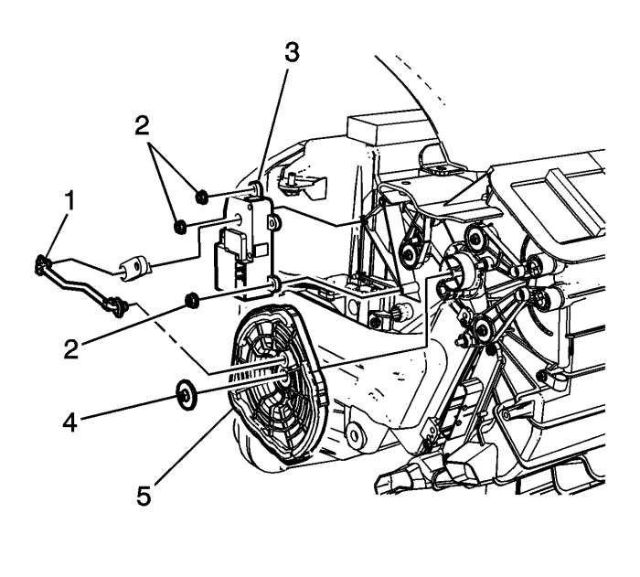
- Remove the screws retaining the mode cam bracket (1) to the evaporator case assembly.
- Remove the mode cam bracket (1) from the evaporator case assembly.
- Remove the mode cam (2) and the mode cam levers (3) from the evaporator case assembly.
Installation Procedure
- Install the mode cam levers (3) to the evaporator case assembly.
- Align and install the mode cam (2) to the mode cam levers (3). Rotate the mode cam (2) to verify mode door operation.
- Install the mode cam bracket (1) to the evaporator case assembly.
Caution: Refer to Fastener Caution in the Preface section.
- Install the mode cam bracket screws to the evaporator case assembly and tighten the screws to 1.5 N·m (13 lb in).
- Install the mode actuator to the evaporator case assembly.
- Install the mode actuator screws to the evaporator case assembly and tighten the screws to 1.5 N·m (13 lb in).
- Connect the electrical connector to the mode actuator.
- Install the communication interface module, if equipped. Refer to Communication Interface Module Replacement .
- Install the driver knee bolster. Refer to
Driver Knee Bolster Replacement : Long Body → Short Body .
Note: Any time a mode actuator or the HVAC control module is replaced, the HVAC control module must be calibrated to ensure correct air distribution.
- Calibrate the actuators.
- Cycle the ignition and verify correct operation.
| © Copyright Chevrolet. All rights reserved |


