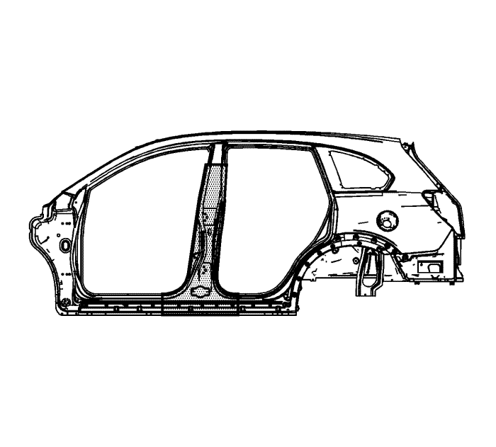
Centre Pillar Sectioning
Removal Procedure
Note : Section in specified areas only. Sectioning outside of these areas may compromise the structural integrity of the vehicle. The door frame can be replaced at factory seams, but requires the removal of the windscreen and the roof. The sectioning procedures have been developed as a more cost-effective alternative to complete replacement. The specific area to be sectioned is determined by the extent of the damage to the vehicle.
- Disable the supplemental inflatable restraint (SIR) system. Refer to SIR Disabling and Enabling .
- Disconnect the negative battery cable. Refer to Battery Negative Cable Disconnection and Connection .
- Remove all related panels and components.
- Repair as much of the damage as possible to factory specifications. Refer to
Dimensions - Body : C105/Short Body → C100/Long Body .
Warning : Foam sound deadeners must be removed from areas within 152.4 mm (6 in) of where flame is to be used for body repairs. When reinstalling foam sound deadeners, avoid inhaling fumes as bodily injury may result.
- Note the location and remove the sealers and anti-corrosion materials from the repair area, as necessary. Refer to Anti-Corrosion Treatment and Repair .
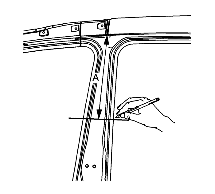
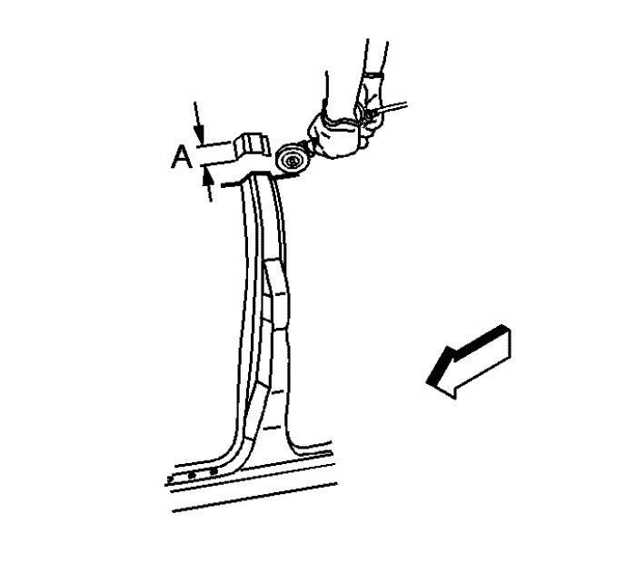
- On the original outer door frame, measure down from the lower edge of the door opening 135 mm (5.3 in) (A) and mark a horizontal line.
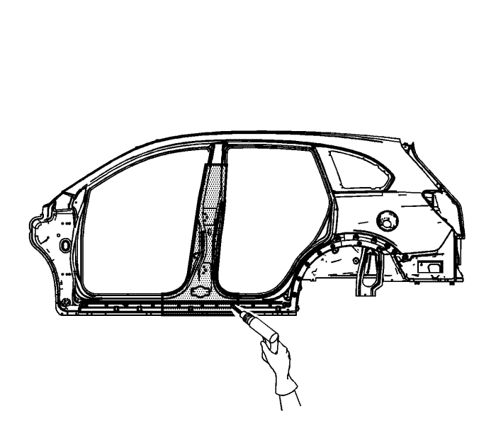
Note : Do NOT damage any inner panels or reinforcements.
- Cut the panel where sectioning is to be performed.
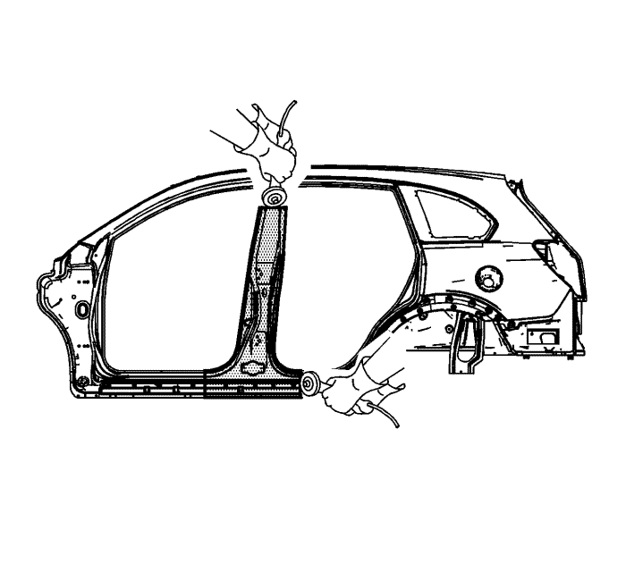
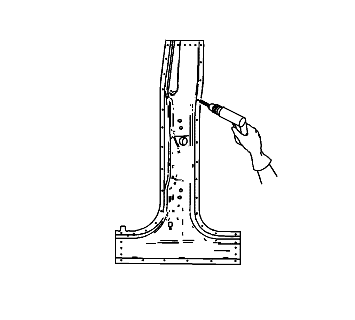
- Locate and drill out all factory welds. Note the number and location of the welds for installations of the service part.
- Remove the damaged centre pillar section.
Installation Procedure
- Cut the replacement centre pillar section in corresponding locations to fit the original panel. The sectioning joint should be trimmed to allow 1½ times the metal thickness at the sectioning joint.
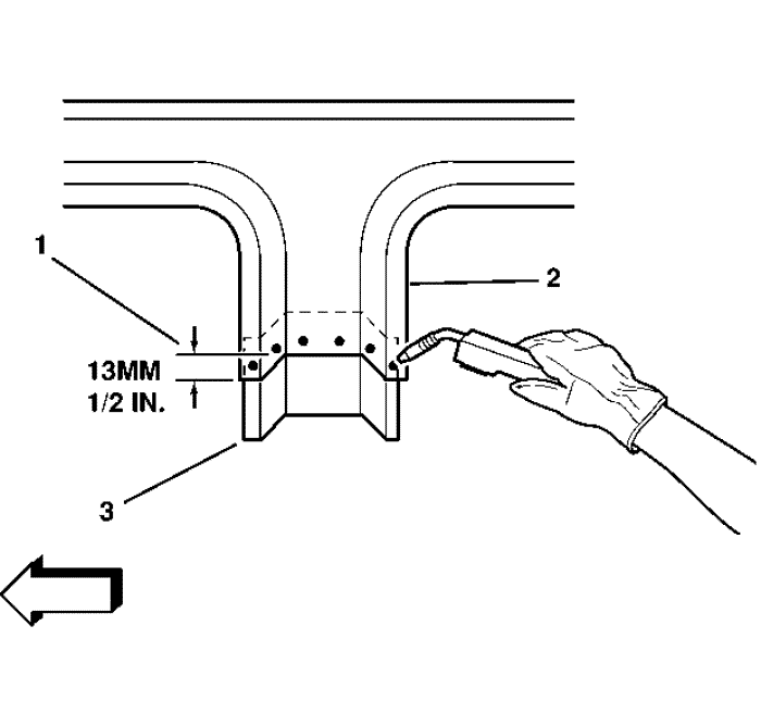
- Create a 50-mm (2-in) backing plate (A) from the unused portion of the service part. Trim the backing plate as necessary to fit behind the sectioning joint where there is no reinforcement.
- Drill 8-mm (5/16-in) plug weld holes along the sectioning cut on the remaining original part. Locate these holes 13 mm (1/2 in) from the edge and spaced 40 mm (1½ in) apart.
Note : In any area damaged beyond recognition, or if structural Weld-Thru adhesive is present, space the plug weld holes 40 mm (1½ in) apart.
- Drill 8-mm (5/16-in) plug weld holes in the service part as necessary in the locations noted from the original panel and along the sectioning cut.
- Prepare all mating surfaces as necessary.
- Apply 3M® Weld-Thru coating P/N 05916 or equivalent, to all mating surfaces.
- Fit the backing plate halfway into the sectioning joint, clamp and plug weld to the vehicle.
- Position the centre pillar.
- Plug weld accordingly.
Note : To create a solid weld with minimum heat distortion make 25-mm (1-in) stitch welds along the seam with 25-mm (1-in) gaps between. Then go back and complete the stitch weld.
- Stitch the weld sectioning joint.
- Clean and prepare all welded surfaces.
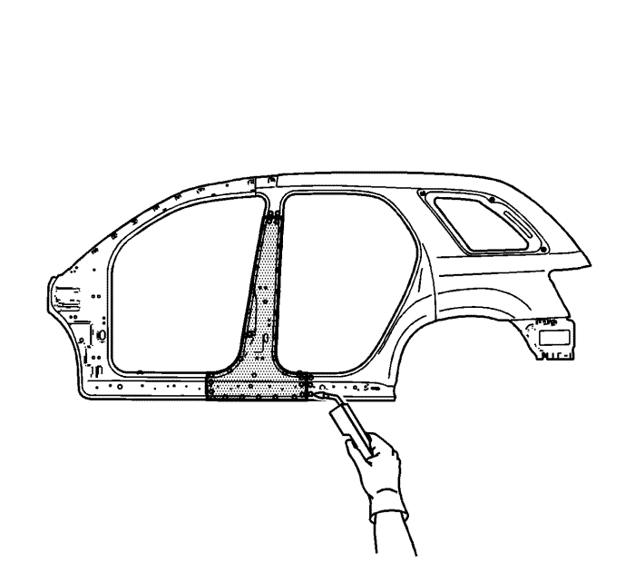
- Apply the sealers and anti-corrosion materials to the repair area, as necessary. Refer to Anti-Corrosion Treatment and Repair .
- Paint and repair the area. Refer to Basecoat/Clearcoat Paint Systems .
- Install all related panels and components.
- Connect the negative battery cable. Refer to Battery Negative Cable Disconnection and Connection .
- Enable the SIR system. Refer to SIR Disabling and Enabling .
| © Copyright Chevrolet. All rights reserved |


