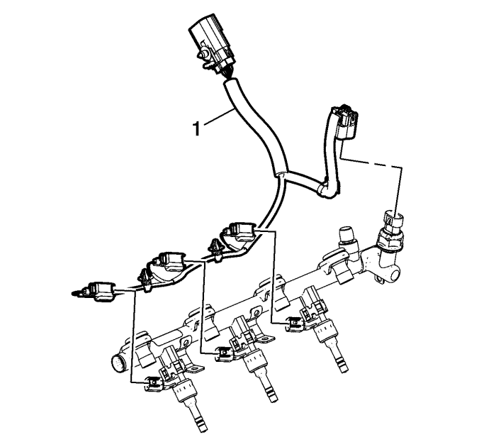
- Disconnect and remove the fuel rail wiring harness (1).
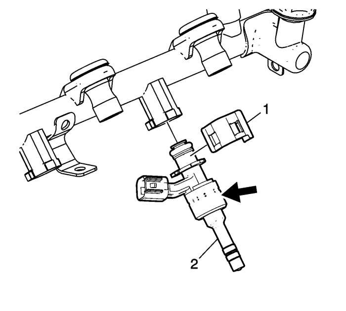
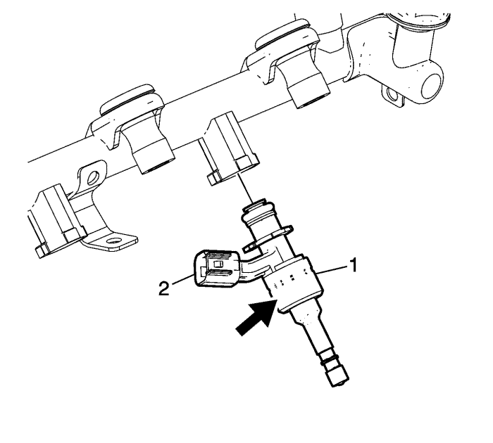
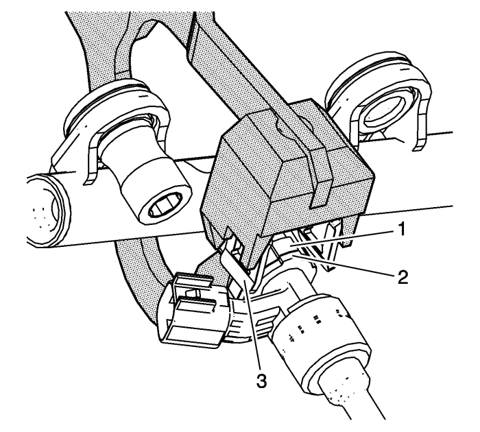
- Taking care not to touch or apply force to the injector tip or electrical connector, remove the fuel injector retainer (1) by spreading both sides at the same time. A pair of large, sturdy circlip pliers can help with this. Discard the retainer.
- Holding the largest diameter/body of the injector only, indicated by arrow in the graphic, and using a slight twisting motion, remove the fuel injector (2) from the fuel rail.
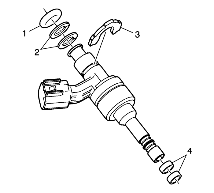
- Using pliers, remove the fuel injector bush (3) straight out from the injector body. Discard bush (3). Remove and discard the fuel injector O-ring (1) and plastic spacers (2).
- Remove and discard the fuel injector seals (4).
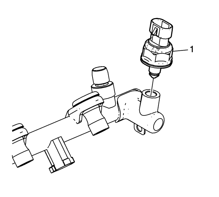
Note: Applying force to the plastic housing of the sensor will destroy the sensor. To tighten or loosen, only apply force to the attached hexagon.
- Remove the fuel pressure sensor (1).
Note: Do not soak or submerge the fuel rail or injectors in solvent.
- Clean the exterior of the fuel rail and injectors with solvent.
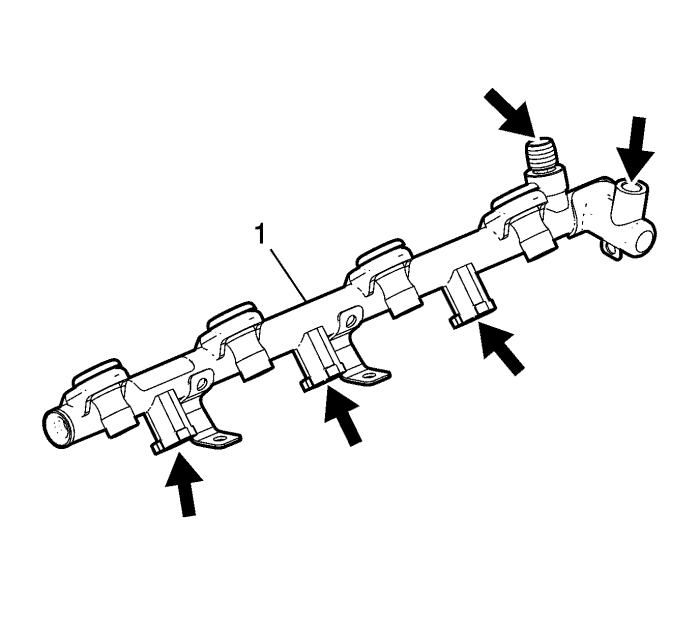
- Inspect the fuel rail (1) and components for the following conditions:
| • | Damage, debris or restrictions to the fuel rail |
| • | Damage, debris or restrictions to the fuel ports in the fuel rail |
| • | Damage to the mounting area for the fuel rail |
| • | Damage to the fuel rail mounting bolts or mounting bolt grommets/isolators |
| • | Damage to the threads on the fuel rail feed fitting |
| • | Damage to the threads in the fuel pressure sensor bore |
| • | Damage to the fuel pressure sensor connector, threads, or sealing face |
Note: Applying force to the plastic housing of the sensor will destroy the sensor. To tighten or loosen, only apply force to the attached hexagon.
- Install the fuel pressure sensor (1).
| | Note: Ensure that the fuel rail threads have been cleaned of any excess fuel or the fuel pressure sensor will NOT seal properly. |
| 9.3. | Install the fuel pressure sensor hand tight. |
| 9.4. | Remove the fuel pressure sensor and re-lubricate. |
Caution: Refer to Fastener Caution in the Preface section.
| 9.5. | Install the fuel pressure sensor and tighten to 33 N·m (25 lb ft). |
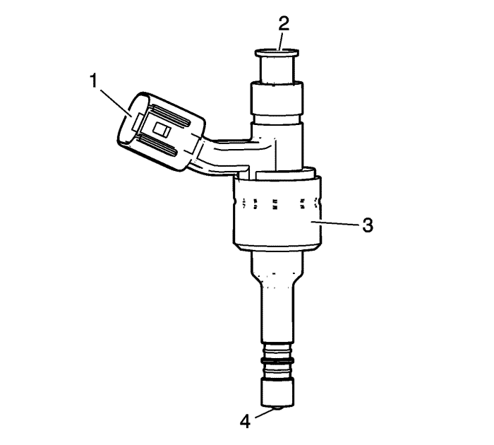
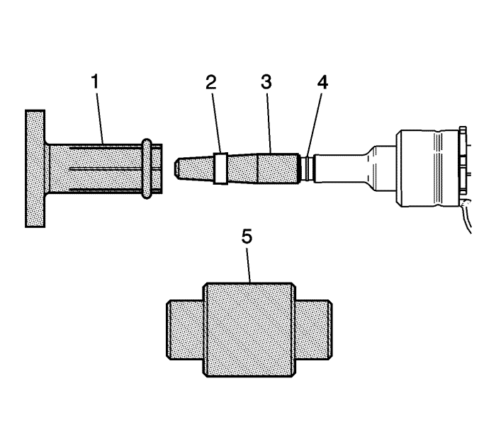
- Inspect the fuel injectors for the following conditions:
| • | Damage to the fuel injector connector (1) |
| • | Damage to the fuel inlet cone (2) |
| • | Damage to the fuel injector body (3) |
| • | Damage to the fuel injector tip (4) |
- Replace the fuel rail or injector if any damage is found. Do not attempt to repair a fuel rail or injector.
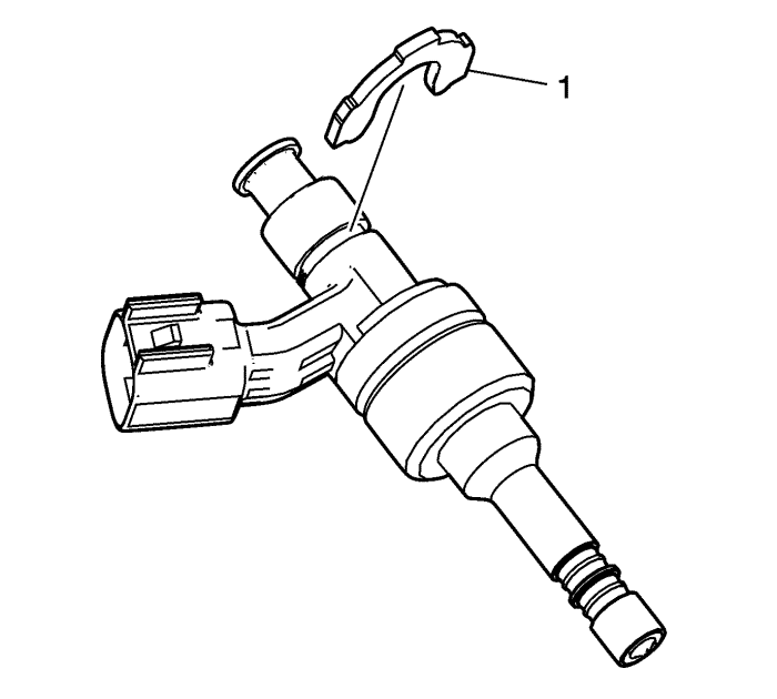
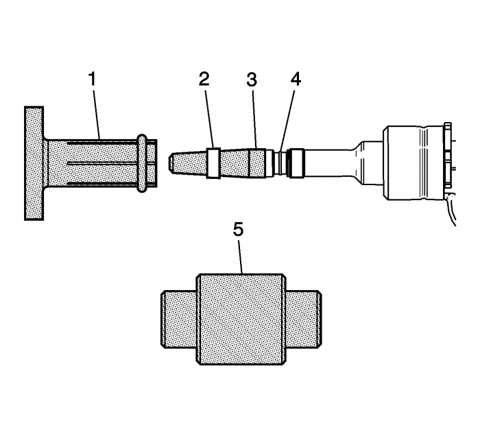
Note: The fuel injector bush (1) is to be installed BEFORE O-ring or backup rings are installed.
- Install NEW fuel injector bush (1) onto injector body. Bush should seat with a distinct "snap" sound and feel. Ensure bush is fully seated.
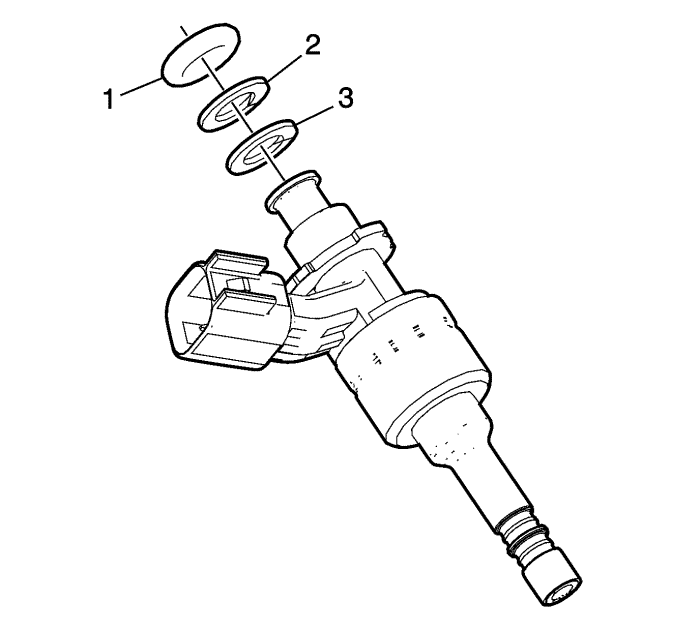
- Install the NEW white plastic spacer (3) on the fuel injector first.
- Install the brown plastic spacer (2) second.
- Lubricate the NEW O-ring (1) with 5W30 engine oil.
Note: Do NOT install the Teflon injector tip/bore seals until AFTER the injectors have been installed on the fuel rail.
- Holding the largest diameter/body of the injector only, indicated by the arrow in the graphic, insert the injector assembly (1) into the fuel rail. Ensure correct orientation of the electrical connector (2).
- Clamp the fuel rail in a bench vice USING SOFT JAWS to aid in holding the rail during the installation of the retainer.
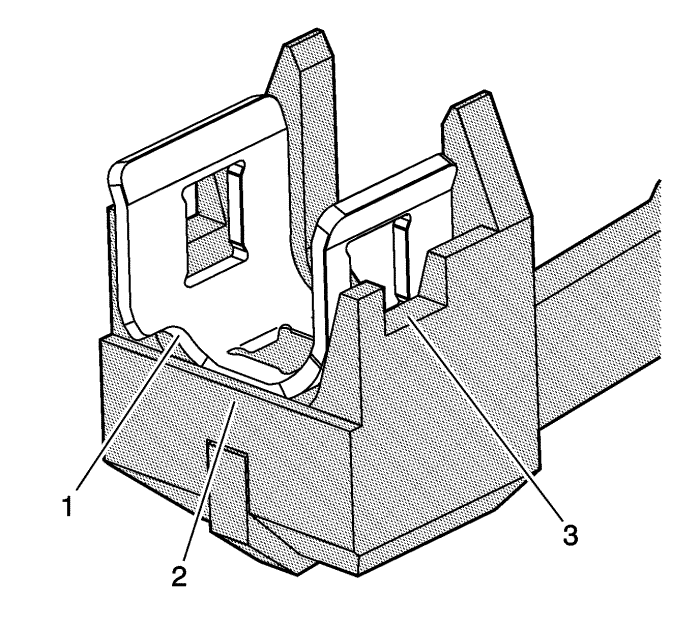
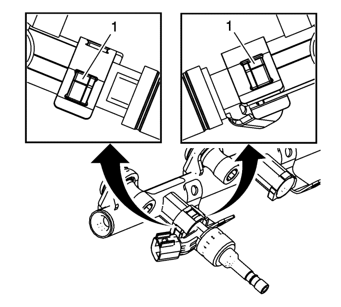
Note: Ensure the retainer is set properly into EN 49247 installer .| • | The notch should always face forward (1) |
| • | The retainer should be behind the plate (2) |
| • | The tool windows allow for visual alignment (3) |
- Install the fuel injector retainer onto the EN 49247 installer .
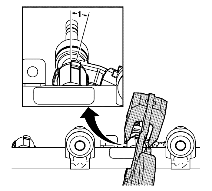
- Note the following points when preparing to use the EN 49247 installer .
There is a 15-degree angle of rotation (1) with the fuel rail flanges relative to the fuel rail. You must hold the EN 49247 installer at a similar angle to ensure installing the retainer properly.
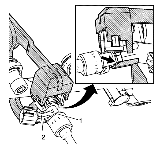
- The retainer (1) should almost touch the electrical connector (2), and the base of the EN 49247 installer should be positioned as shown before you begin to squeeze the tool to complete the installation. This will help ensure the retainer is properly located relative to the injector and fuel rail flanges.
- Holding the injector bush (2) and fuel rail flanges (1) in alignment, and holding the injector assembly firmly against the fuel rail so there is no gap between (1) and (2), install the fuel injector retainer (3).
Caution: Ensure the fuel injector retainer is properly installed. Failure to completely install the retainers may degrade fuel injection system performance or cause system malfunction.
- Ensure all 3 fuel injector bush tabs and fuel rail flanges (1) are properly and completely captured by the fuel injector retainer.
- Repeat for remaining injectors until all are installed and retained in the fuel rail.
- Install the fuel rail wiring harness (1).
Note: Do not use any type of lubricant when installing the NEW seals (2) on the fuel injector tip.
- Install EN 49245-1 long protector (3) onto the fuel injector tip, covering the first recessed area closest to the tip. Place a NEW seal (2) on EN-49245-1 long protector .
- Using EN-49245-3 pusher (1), install the seal into the second recessed area (4) of the fuel injector.
Note: The EN-49245-4 sizer is two-sided, and either direction will size the seal correctly.
- Compress the seal with your fingers, then resize the seal using the EN-49245-4 sizer (5).
Note: Do not use any type of lubricant when installing the NEW seals (2) on the fuel injector tip.
- Install EN-49245-2 short protector (3) onto the fuel injector tip. Place a NEW seal (2) on EN-49245-2 short protector .
- Using EN-49245-3 pusher (1), install the seal into the first recessed area (4) of the fuel injector.
Note: The EN-49245-4 sizer is two-sided, and either direction will size the seal correctly.
- Compress the seal with your fingers, then resize the seal using the EN-49245-4 sizer (5).


