To the top of the document
Captiva
   
GMDE Start Page Load static TOC Load dynamic TOC Help?

Electronic Parking Brake Control Module Replacement

Removal Procedure

  1. Disable the handbrake cable adjuster. Refer to Handbrake Cable Adjuster Disabling .
  2. Turn the ignition to the OFF position.
  3. Raise and support the vehicle. Refer to Lifting and Jacking the Vehicle .

  4. 2420590
  5. Disconnect the handbrake intermediate cable nut (1) from the electronic handbrake control module spindle by rotating the nut anticlockwise.
  6. Disconnect the handbrake intermediate cable and position the cable aside.

  7. 2420597
  8. Remove the electronic handbrake control module front cover (1).
  9. Disconnect the electronic handbrake control module electrical connector.

  10. 2420604
  11. Remove the electronic handbrake control module bracket bolts (1).

  12. 2420608
  13. Remove the electronic handbrake control module and bracket assembly (1).

  14. 2420612
  15. If necessary, remove the electronic handbrake control module bolts (1).

  16. 2420615
  17. Remove the electronic handbrake control module bracket (1).
  18. Inspect the electronic handbrake control module bracket sleeves and insulators. Replace any damaged or missing sleeves or insulators.

  19. 2420621
  20. Remove the electronic handbrake control module (1) from the rear cover.

Installation Procedure


    2420621
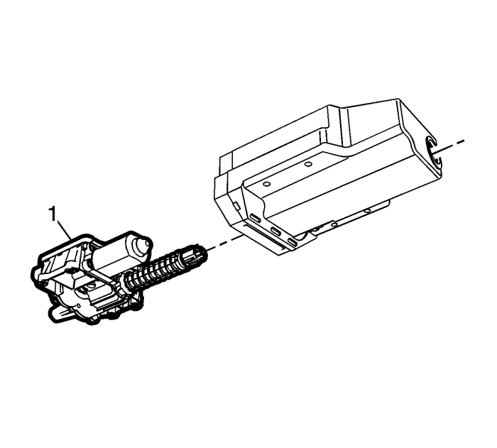
  1. Install the electronic handbrake control module (1) to the rear cover.

  2. 2420615
  3. Install the electronic handbrake control module bracket (1) to the electronic handbrake control module, if removed.
  4. Caution: Refer to Fastener Caution in the Preface section.


    2420612
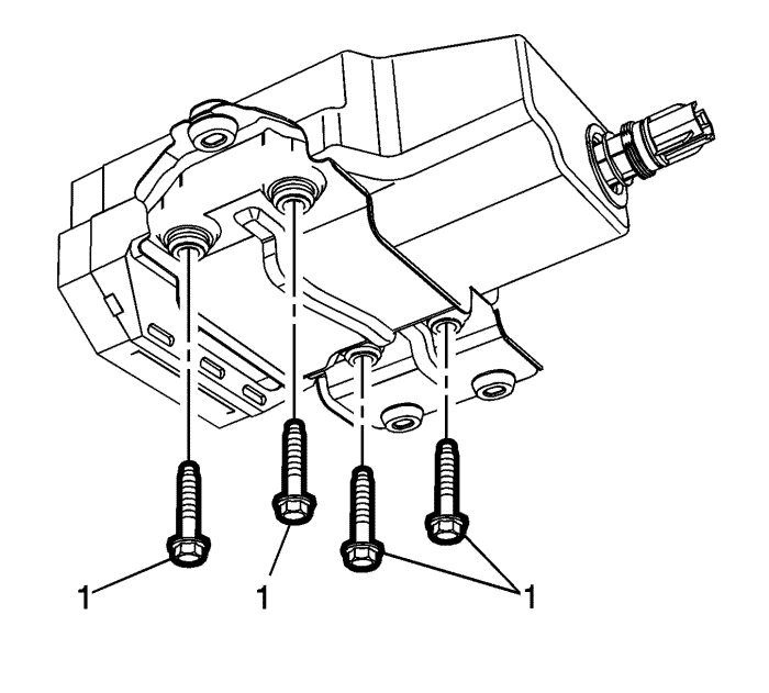
  5. Install the electronic handbrake control module bolts (1) and tighten the bolts to 9 N·m (80 lb in).

  6. 2420608
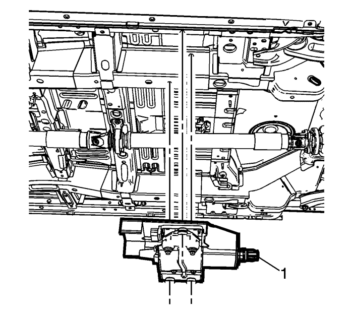
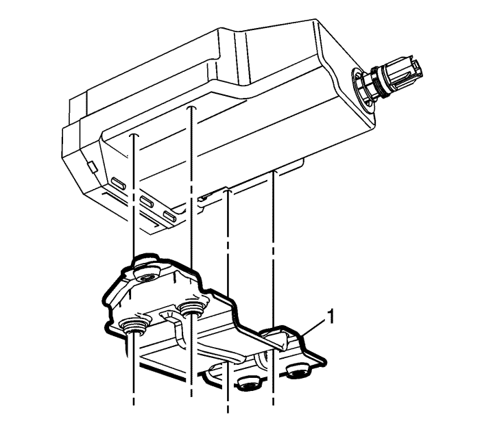
  7. Install the electronic handbrake control module and bracket assembly (1).

  8. 2420604
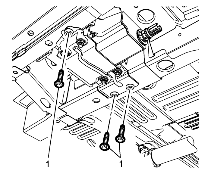
  9. Install the electronic handbrake control module bracket bolts (1) and tighten the bolts to 10 N·m (89 lb in).

  10. 2420597
  11. Connect the electronic handbrake control module electrical connector.
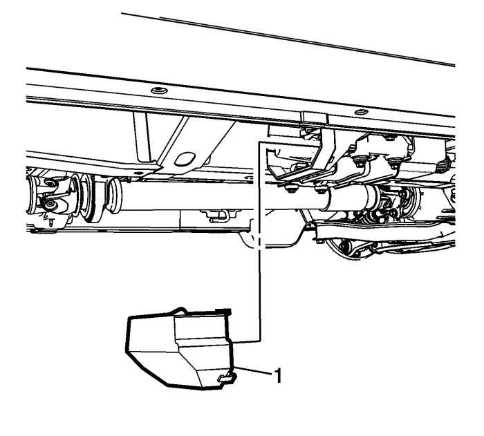
  12. Install the electronic handbrake control module front cover (1).

  13. 2420590
  14. Inspect the O-ring seals on the electronic handbrake control module spindle and the handbrake intermediate cable for damage and correct positioning and replace, if necessary.
  15. Note: Ensure the park brake intermediate cable fitting is engaged in the actuator in the spindle.

  16. Install the handbrake intermediate cable fitting to the spindle.
  17. Note: When installing the handbrake intermediate cable nut to the electronic park brake module spindle, hold the spindle housing securely to avoid distorting the housing.

  18. Connect the handbrake intermediate cable nut (1) to the electronic handbrake control module spindle by rotating the nut clockwise and tighten to 6 N·m (53 lb in).
  19. Enable the handbrake cable adjuster. Refer to Handbrake Cable Adjuster Enabling .


© Copyright Chevrolet. All rights reserved