Captiva |
||||||||
|
|
|
|||||||
| • | J-42991 Strut Rod Nut Socket |
| • | J-45400 Strut Spring Compressor |
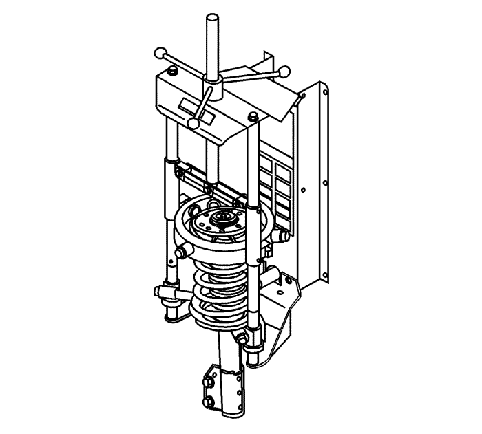
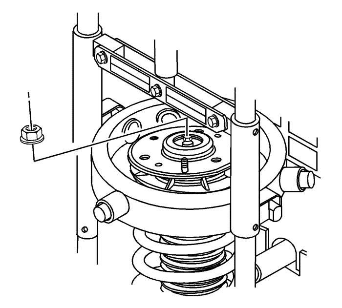
Caution: Do not allow the absorber rod to rotate during disassembly/reassembly. Use hand tools to keep the absorber rod from rotating. If air tools are used, and the rod is allowed to rotate, damage to the absorber may occur.
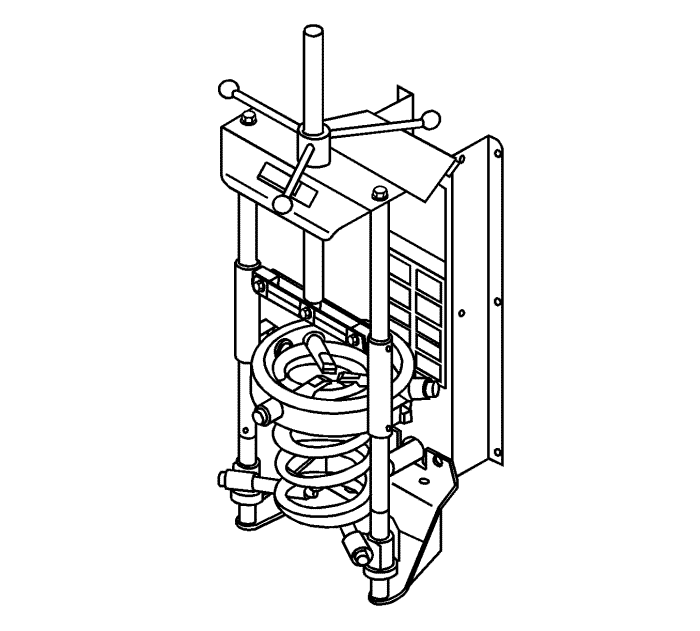
Note: Leave the spring in the spring compressor.
Caution: Do not handle the top mount assembly by the plastic portion. Handle the top mount assembly by the metal portion when removing/installing the top mount from/to the strut assembly. Holding the top mount assembly by the plastic portion may loosen the snap fit of the bearing components and cause the bearing to fall apart.
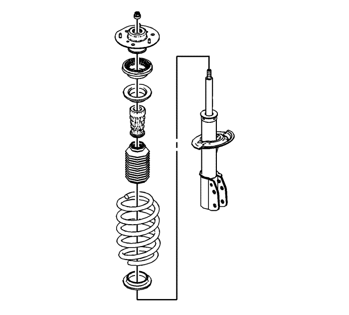
Note: Replace any components that are found to have excessive wear or are damaged.
Note: The tag identifying the spring will be closer to the bottom of the spring. The end of the coil sits up against the tab on the spring seat.
Note: The anti-rotation tab on the spring seat must face 180 degrees from the direction that the knuckle bracket points.
Caution: Do not handle the top mount assembly by the plastic portion. Handle the top mount assembly by the metal portion when removing/installing the top mount from/to the strut assembly. Holding the top mount assembly by the plastic portion may loosen the snap fit of the bearing components and cause the bearing to fall apart.
Note: The flat on the metal plate of the top mount assembly must face the same direction of the anti-rotation tab on the spring seat.
Caution: Refer to Fastener Caution in the Preface section.
Caution: Do not allow the absorber rod to rotate during disassembly/reassembly. Use hand tools to keep the absorber rod from rotating. If air tools are used, and the rod is allowed to rotate, damage to the absorber may occur.
| © Copyright Chevrolet. All rights reserved |


