Balancer Installation
Special Tools
| • | EN-50430 Balance Shaft Module Locking Pin |
| • | EN-50431 BSM Backlash Measure Adaptor |
For equivalent regional tools, refer to Special Tools .
- Set the piston of cylinder #1 to TDC of combustion stroke.
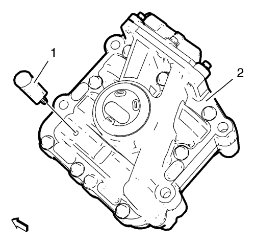
- Install the EN-50430 locking pin (1) and lock the gear of the balance shaft module (2)
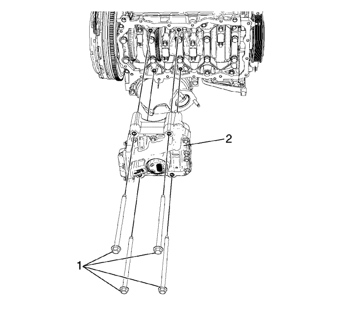
- Install the balance shaft module (2) to the lower crankcase.
Note: Install the balance shaft module retaining bolts in a cross sequence.
- Install 4 balance shaft module retaining bolts (1). Tighten the bolts (1) only to the extent to which the balance shaft module (2) is still sliding on the lower crankcase.
- Remove the EN-50430 locking pin .
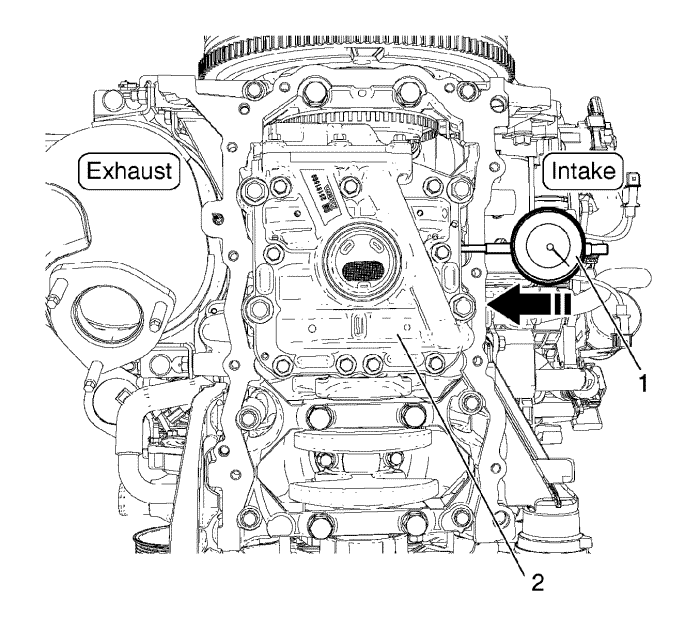
- Install the dial gauge (1) on the balance shaft module intake side centre.
- Push the balance shaft module (2) from intake side to exhaust side (zero backlash).
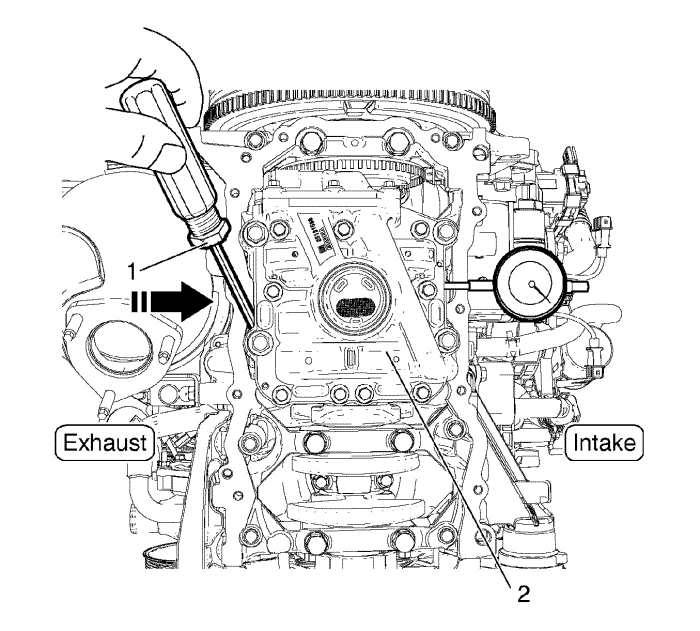
- Set the driver (1) into the exhaust side as shown in the graphic and push the balance shaft module (2) 1.1 mm to the intake side.
Caution: Refer to Fastener Caution in the Preface section.
- Install and tighten balance shaft module retaining bolts (1) in cross sequence.
Tighten
First Pass: 20 N·m (14.7 lb ft)
- Check the balance shaft module backlash specifications (0.046-0.128 mm). Refer to Balancer Cleaning and Inspection .
Tighten
Final Pass: 50 N·m + 90° (36.8 lb ft + 90°)
| © Copyright Chevrolet. All rights reserved |


