Captiva |
||||||||
|
|
|
|||||||
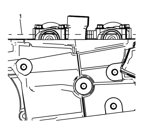
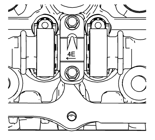
| • | The raised feature must always be oriented toward the center of the cylinder head. |
| • | The I indicates the intake camshaft. |
| • | The E indicates the exhaust camshaft. |
| • | The number 2, 4, 6 indicates the cylinder position from the front of the engine. |
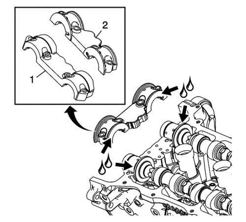
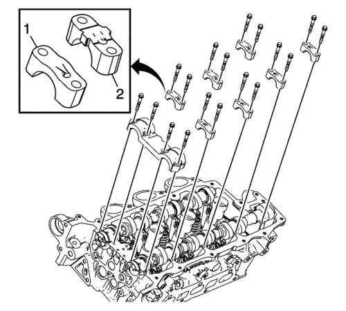
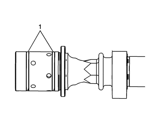
Note: There are first design (1) and second design (2) camshaft intermediate bearing caps.
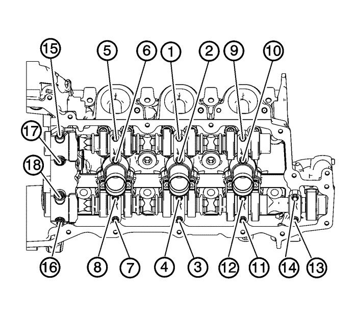
Caution: Refer to Fastener Caution in the Preface section.
| © Copyright Chevrolet. All rights reserved |


