Captiva |
||||||||
|
|
|
|||||||
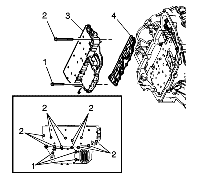
Caution: Use care when removing or installing the filter plate assembly. A broken or missing retaining tab may not adequately secure the filter plate to the control solenoid valve assembly, resulting in possible damage or contamination.
Caution: Use care when removing or installing the filter plate assembly. A broken or missing retaining tab may not adequately secure the filter plate to the control solenoid valve assembly, resulting in possible damage or contamination.
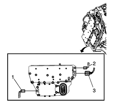
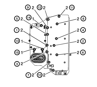
Caution: Refer to Fastener Caution in the Preface section.
Note: The Transmission Adaptive Values Learn procedure must be performed when one of the following repairs has been made to the vehicle. Failure to perform the procedure after one of the following repairs may result in poor transmission performance, as well as transmission DTCs being set: • Transmission internal service/overhaul • Valve body repair or replacement • Control solenoid valve assembly replacement • TCM software/calibration update • Any service in response to a shift quality concern
| © Copyright Chevrolet. All rights reserved |


