Crankshaft and Bearing Cleaning and Inspection
Special Tools
| • | EN-45059 Torque Angle Sensor Kit |
For equivalent regional tools, refer to Special Tools .
Cleaning Procedure
- Clean the following components in solvent:
| • | Connecting rod bearings |
| • | Crankshaft oil passages |
| • | Crankshaft threaded holes |
Warning: Refer to Safety Glasses and Compressed Air Warning in the Preface section.
- Dry the following components with compressed air:
| • | Connecting rod bearings |
| • | Crankshaft oil passages |
| • | Crankshaft threaded holes |
Visual Inspection
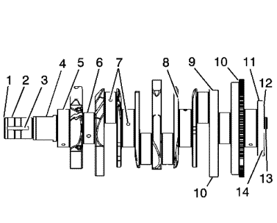
- Perform the following visual inspections:
| • | Inspect the crankshaft balancer bolt hole (1) for thread damage. |
| • | Inspect the crankshaft keyway (3) for damage. |
| • | Inspect the oil pump drive flats (4) for damage. |
| • | Inspect the crankshaft main journals (5) for damage. |
| • | Inspect the crankshaft connecting rod journals (6) for damage. |
| • | Inspect the crankshaft oil passages (7) for obstructions. |
| • | Inspect the crankshaft main bearing thrust wall surfaces (8) for damage. |
| • | Inspect the crankshaft counterweights (9) for damage. |
| • | Inspect the crankshaft position sensor inner excitor ring (10) for damage. |
| • | Inspect the crankshaft rear main oil seal surface (11) for damage. |
| • | Inspect the crankshaft engine flywheel mounting surface (12) for damage. |
| • | Inspect the crankshaft pilot hole (13) for damage. |
| • | Inspect the crankshaft engine flywheel bolt holes (14) for thread damage. |
- Repair or replace the crankshaft as necessary.
Crankshaft and Bearing Inspection
- Inspect for fatigue indicated by craters or pockets. Flattened sections on the bearing halves also indicate fatigue.
- Inspect for excessive scoring or discoloration on both front and back of the bearing halves.
- Inspect the main bearings for dirt embedded into the bearing material.
- Inspect for improper seating indicated by bright, polished sections.
Crankshaft End Play, Check
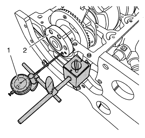
Note : Crankshaft (2) attached with crankshaft bearing caps.
- Install the GE-49449 gauge (1)
| • | Install in the holder on the front of the engine block. |
| • | Place the dial gauge plunger (1) against the crankshaft and adjust. |
- Measure the longitudinal play of the crankshaft.
| • | Move the crankshaft in the longitudinal direction. |
| • | Permissible crankshaft end play: 0.09-0.35 mm (0.0036-0.0138 in). |
- Remove the GE-49449 gauge .
Crankshaft Out-of-Round, Check
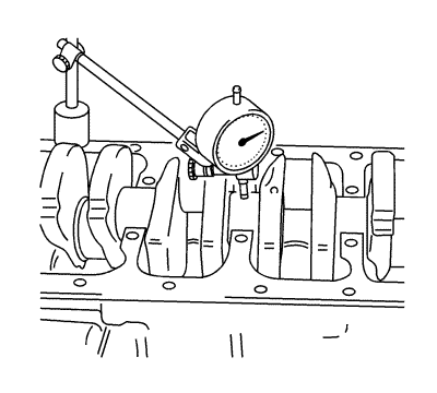
Note: Crankshaft removed.
- Insert the crankshaft in the engine block.
- Install the GE-49449 gauge
| • | Attach to the bracket on the engine block. |
| • | Place the dial gauge plunger against the crankshaft bearing journal and adjust. |
- Check the rotational play of the crankshaft.
| • | Turn the crankshaft evenly. |
| • | Maximum permissible rotational play: 0.03 mm (0.0012 in). |
- Remove the GE-49449 gauge .
Check Crankshaft Bearing Clearance (With Plastigage)
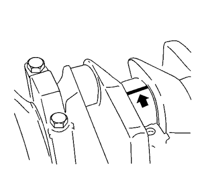
- Lay on a suitable plastigage.
Lay out Plastigage (flexible plastic thread) around the entire width of the con-rod bearing journal (arrow).
- Install the lower crankcase (1).
Caution: Refer to Fastener Caution in the Preface section.
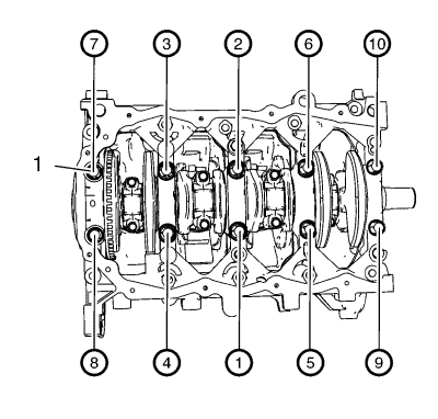
- Install the 10 lower crankcase bolts (1) in a sequence as in the graphic shown and tighten in three passes:
| 3.1. | First pass in sequence to 25 N·m (19 lb ft). |
| 3.2. | Second pass in sequence to an additional 45 degrees using the EN-45059 angle sensor . |
| 3.3. | Third pass in sequence to an additional 90 degrees using the EN-45059 angle sensor . |
Note: Do not rotate the crankshaft.
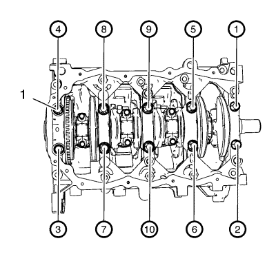
- Remove the 10 lower crankcase bolts in a sequence as in the graphic shown.
- Remove the lower crankcase (1).
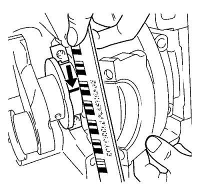
Note: When reading the value, do not confuse millimeters and inches on the measuring scale.
- Measure the crankshaft bearing play.
| • | Compare the width of the flattened plastic thread (arrow) to the measuring scale. |
| • | Permissible crankshaft bearing play: 0.02-0.04 mm (0.001-0.003 in). |
Check Crankshaft Bearing Clearance (With Micrometer Gauge Internal Measuring Device)
Caution: Refer to Fastener Caution in the Preface section.
Note:
| • | Consider the correct tightening sequence. |
- Install the lower crankcase with the crankshaft bearings to the engine block.
Caution: Refer to Fastener Caution in the Preface section.

- Install the lower crankcase (1).
- Install the 10 lower crankcase bolts (1) in a sequence as in the graphic shown and tighten in three passes:
| 2.1. | First pass in sequence to 25 N·m (19 lb ft). |
| 2.2. | Second pass in sequence to an additional 45 degrees using the EN-45059 angle sensor . |
| 2.3. | Third pass in sequence to an additional 90 degrees using the EN-45059 angle sensor . |
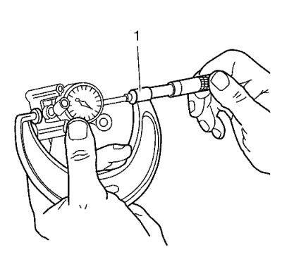
- Install the inner plunger and calibrate with the micrometer gauge (1).
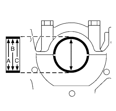
- Measure the crankshaft bearing diameter at 3 points.
Measure at points I, II and III with the internal measuring device.
Calculate the average crankshaft bearing diameter.
Formula: A+ B+ C /3.
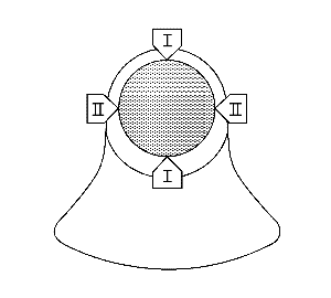
- Measure the crankshaft bearing journal diameter at 2 points.
Measure at points I and II with the micrometer gauge.
- Calculate the average crankshaft bearing journal diameter.
Formula: I + II/2.
- Determine the crankshaft bearing play.
Calculation formula: average crankshaft bearing diameter minus average crankshaft bearing journal diameter.
- Nominal-Actual comparison.
Permissible crankshaft bearing play: 0.02-0.04 mm (0.001-0.003 in).
| © Copyright Chevrolet. All rights reserved |


