Warning: Refer to Brake Dust Warning in the Preface section.
Note:
| • | Brake disc thickness variation MUST be checked BEFORE checking for assembled lateral runout (LRO). Thickness variation exceeding the maximum acceptable level can cause brake pulsation. Refer to Brake Disc Thickness Variation Measurement . |
| • | Brake disc assembled LRO exceeding the maximum allowable specification can cause thickness variation to develop in the brake disc over time, usually between 4,800-11,300 km (3,000-7,000 mi). Refer to Brake Disc Assembled Lateral Runout Measurement . |
- Rotate the brake disc to position the high spot, identified and marked during the brake disc assembled LRO measurement procedure, to face upward.
- Remove the CH-45101-100 Conical Brake Disc Washers and the lug nuts that were installed during the assembled LRO measurement procedure and/or the indexing correction procedure.
- Inspect the mounting surface of the hub/axle flange and the brake disc to ensure that there are no foreign particles or debris remaining.
- Select the correction plate, following the manufacturer's instructions, which has a specification closest to the assembled LRO measurement.
For example: If the assembled LRO measurement was 0.076 mm (0.003 in), the 0.076 mm (0.003 in) correction plate would be used. If the measurement was 0.127 mm (0.005 in), the 0.152 mm (0.006 in) correction plate would be used.
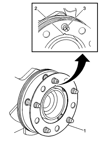
- Determine the positioning for the correction plate (1) using the high spot mark (3) made during the brake disc assembled LRO measurement procedure.
Note:
| • | Do NOT install used correction plates in an attempt to correct brake disc assembled LRO. |
| • | Do NOT stack up, or install more than one correction plate onto one hub/axle flange location, in an attempt to correct brake disc assembled LRO. |
- Install the correction plate (1) onto the hub/axle flange, with the V-shaped notch (2) orientated to align with the high spot mark (3), that was positioned to face upward.
- Install the brake disc to the hub/axle flange. Use the matchmark made prior to removal for proper orientation to the flange.
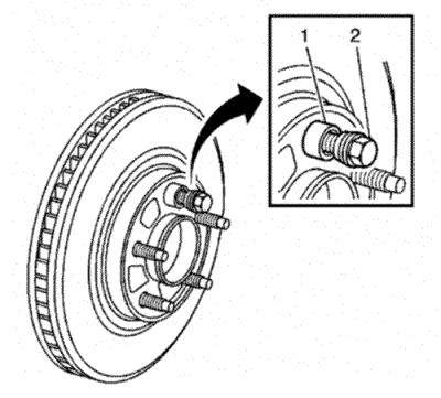
- Hold the disc firmly in place against the hub/axle flange and install one of the CH-45101-100 Conical Brake Disc Washers (1) and one lug nut (2) onto the upper-most wheel stud.
- Continue to hold the disc secure and tighten the wheel nut firmly by hand.
- Install the remaining CH-45101-100 Conical Brake Disc Washers and lug nuts onto the wheel studs and tighten the nuts firmly by hand in a star-pattern.
- Tighten the lug nuts in a star-pattern to specification, in order to properly secure the disc. Refer to Tyre and Wheel Removal and Installation .
- Measure the assembled LRO of the brake disc. Refer to Brake Disc Assembled Lateral Runout Measurement .
- If the brake disc assembled LRO measurement still exceeds the maximum allowable specification, refer to Brake Disc Assembled Lateral Runout Correction .
- If the brake disc assembled LRO measurement is within specification, install the brake calliper and depress the brake pedal several times to secure the disc in place before removing the CH-45101-100 Conical Brake Disc Washers and the lug nuts.


