Tyco/AMP Connectors - 102-Way Inline
Special Tools
| • | EL-38125-580 Terminal Release Tool Kit |
| • | J-38125-11A Terminal Release Tool |
| • | J-38125-212 Terminal Release Tool |
| • | J-38125-216 Terminal Release Tool |
| • | J-38125-221 Terminal Release Tool |
| • | J-38125-560 Terminal Release Tool |
| • | J-38125-566 Terminal Release Tool |
For equivalent regional tools, refer to Special Tools .
Terminal Removal Procedure
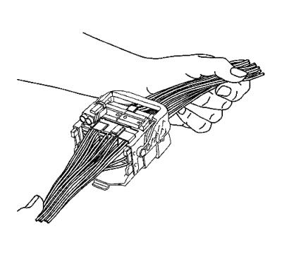
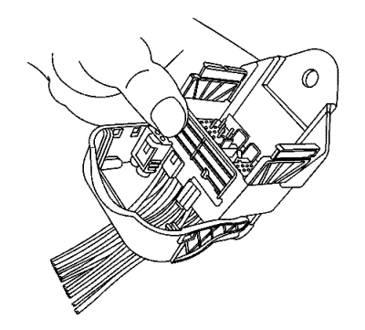
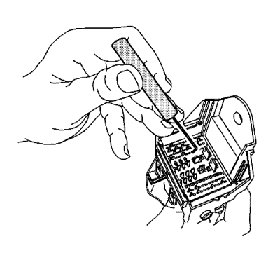
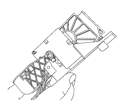
View of a typical connector in the assembled position.
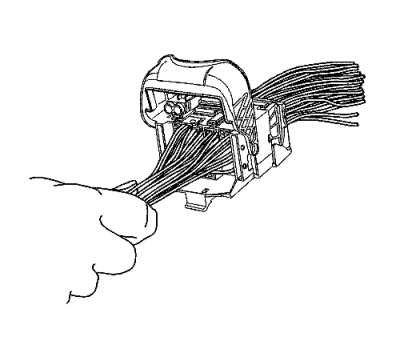
- Pull the locking lever to the 90 degree position from the connector body.
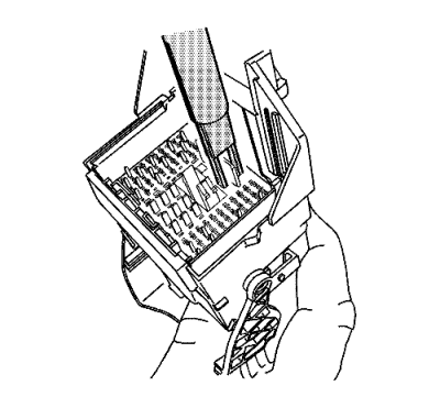
- With the locking lever in the 90 degree position and the male connector body separated, it can be slid outward for removal.
- Slide the male connector body out away from the guide plates.
Note: During assembly the terminal position assurance (TPA) will not fully seat if any terminal is not fully seated.
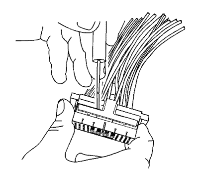
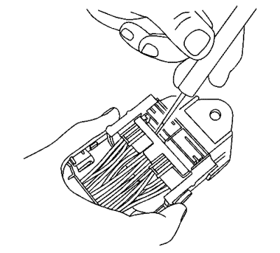
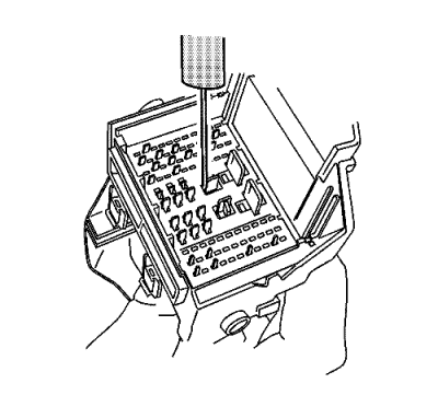
- Using terminal release tool J-38125-11A or equivalent, remove the TPA from the connector body.
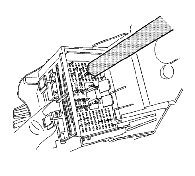
- Using terminal release tool J-38125-566, press the prongs into the holes on each side of the terminal to be removed to release the lock tabs and pull the terminal out of the connector body.
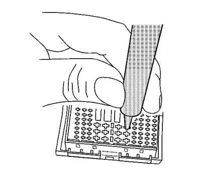
- Using terminal release tool J-38125-560, press the prongs into the holes on each side of the terminal to be removed to release the lock tabs and pull the terminal out of the connector body.
- Using terminal release tool J-38125-221, press the prongs into the holes on each side of the terminal to be removed to release the lock tabs and pull the terminal out of the connector body.
- The female connector body may have an additional connector hooked to the edge of the body. Use terminal release tool J-38125-11A or equivalent to release the locking tab and slide the connector off the female body.
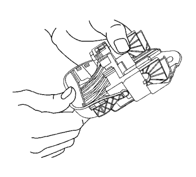
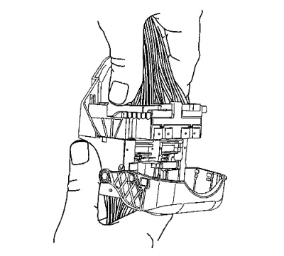
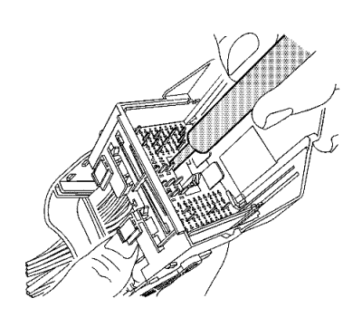
- Move the locking lever 180 degrees from the connected position.
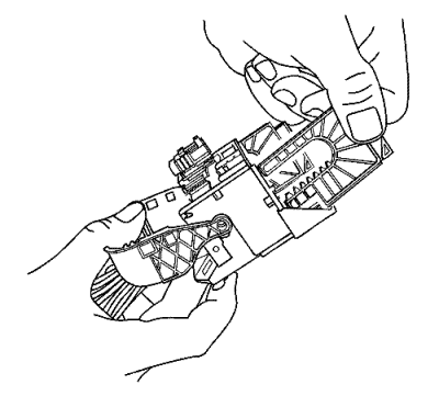
- With the locking lever in the 180 degree position the guide plates can be removed from the connector body.
Note: During assembly the TPA will not fully seat if any terminal is not fully seated.
- Using terminal release tool J-38125-11A or equivalent, remove the TPA from the connector body.
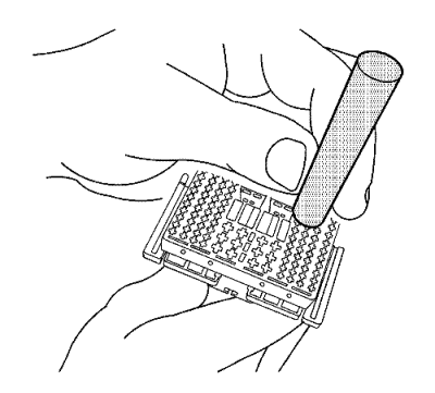
- Using terminal release tool J-38125-216, lift the terminal plate past the terminals and out of the connector body cavity.
- Terminal plate will bind slightly on each corner.
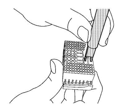
- Using terminal release tool J-38125-221, press the prongs into the holes on each side of the terminal to be removed to release the lock tabs and pull the terminal out of the connector body.
- Using terminal release tool J-38125-212, press the prongs into the holes on each side of the terminal to be removed to release the lock tabs and pull the terminal out of the connector body.
- Using terminal release tool J-38125-560, press the prongs into the holes on each side of the terminal to be removed to release the lock tabs and pull the terminal out of the connector body.
- Press the terminal plate back into the female connector to the preset position. The plate will bind slightly on each corner.
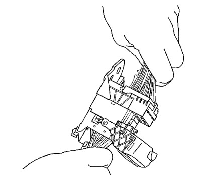
- With the locking lever in the 180 degree position, align the guide plates to mesh with the gears on the locking lever.
- Slide the male connector body back inward toward the guide plates.
- With the locking lever in the 90 degree position and the male connector body connected, it can be slid inward for assembly.
- Move the lever into the locked position or in the assembled position. This will pull the male connector down into the female connector.
- Repair the terminal by following the
Repairing Connector Terminals : Terminated Lead Repair procedure.
- Insert the repaired terminal back into the cavity. Repeat the diagnostic procedure to verify the repair and reconnect the connector bodies.
| © Copyright Chevrolet. All rights reserved |


