Volt |
||||||||
|
|
|
|||||||
Warning: Refer to Brake Dust Warning in the Preface section.
Danger: Do not use a service jack in locations other than those specified to lift this vehicle. Lifting the vehicle with a jack in those other locations could cause the vehicle to slip off the jack and roll; this could cause injury or death.

Note:
• DO NOT use any air tools to remove or install the guide pin bolts. Use hand tools ONLY • Install an open end wrench to hold the calliper guide pin in line with the brake calliper while removing or installing the calliper guide pin bolt. DO NOT allow the open end wrench to come in contact with the brake calliper. Allowing the open end wrench to come in contact with the brake calliper will cause a pulsation when the brakes are applied.
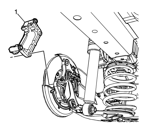
Caution: Support the brake calliper with heavy mechanic wire, or equivalent, whenever it is separated from its mount and the hydraulic flexible brake hose is still connected. Failure to support the calliper in this manner will cause the flexible brake hose to bear the weight of the calliper, which may cause damage to the brake hose and in turn may cause a brake fluid leak.
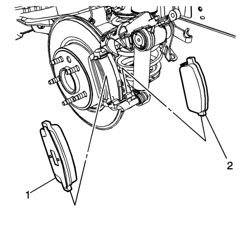
Note: Note the location of the brake pad wear sensor for correct installation.
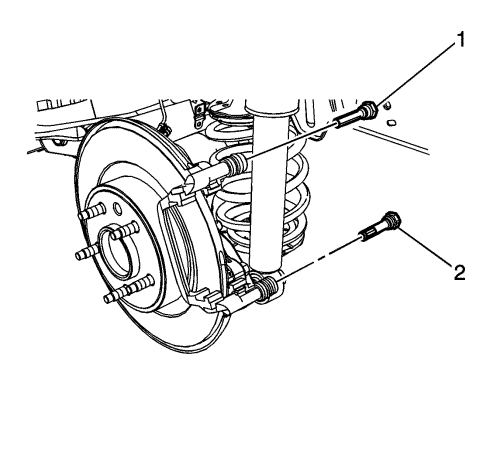
Note: The lower brake calliper guide pin is equipped with a bushing, and must be installed in the same location in the calliper bracket.
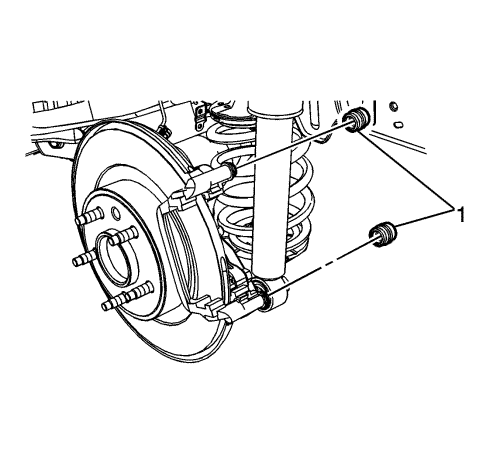
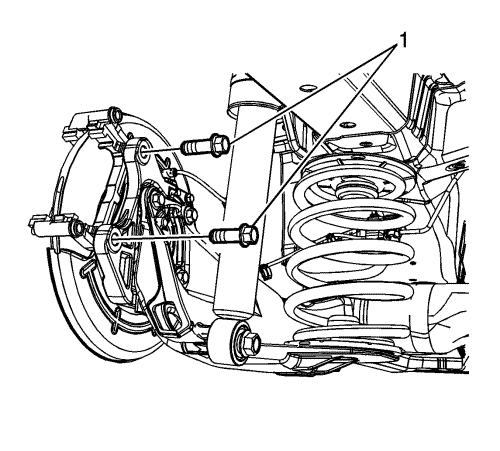
Note: Do not reuse the brake calliper bracket bolts.
Caution: Refer to Fastener Caution in the Preface section.
| 2.1. | Tighten the bolts a first pass to 90 N·m (67 lb ft). |
| 2.2. | Tighten the bolts a final pass an additional 60 degrees. |
Note: The lower brake calliper guide pin is equipped with a bushing, and must be installed in the same location in the calliper bracket.
Note: Note the location of the brake pad wear sensor for correct installation.
| ©© Copyright Chevrolet. All rights reserved |


