To the top of the document
Volt
   
GMDE Start Page Load static TOC Load dynamic TOC Help?

Piston, Connecting Rod, and Bearing Cleaning and Inspection

Visual Inspection And Cleaning Procedure

Connecting Rod

    Warning: Wear safety glasses when using compressed air in order to prevent eye injury.

  1. Clean the connecting rods in solvent and dry with compressed air.
  2. Inspect the connecting rod for the following:
  3. • Signs of being twisted, bent, nicked or cracked
    • Scratches or abrasion on the connecting rod bearing seating surfaces

Piston


    156168
  1. Clean the piston with a cleaning solvent. DO NOT wire brush any parts of the piston.
  2. Clean the piston ring grooves.
  3. Inspect the piston on the following:
  4. • Cracked ring lands, skirts or pin bosses
    • Ring grooves for nicks
    • Eroded areas on the top of the piston (1)
    • Scuffed or damaged skirts (2)
    • Worn gudgeon pin bores (3)
  5. If there is any excessive wear, replace the piston.
  6. Measure the clearance between piston pin and piston bore.

Piston And Connecting Rod Measurement Procedure

Piston Ring Clearance


    2189596
  1. Install the piston rings to the cylinder as shown and measure the piston ring end gap (1). Compare the measurements with those provided below:
  2. • The upper compression ring end gap should be 0.250 mm - 0.400 mm (0.0098 in - 0.0157 in)
    • The lower compression ring end gap should be 0.400 mm - 0.600 mm (0.0157 in - 0.0236 in)
    • The oil ring end gap should be 0.250 mm - 0.750 mm (0.0098 in - 0.0295 in)
  3. If the clearance is greater than the provided specifications, the piston rings must be replaced.

  4. 2189597
  5. Measure the piston ring side clearance as shown (1). Compare the measurements with those provided below:
  6. • The upper compression ring side clearance should be 0.025 mm - 0.070 mm (0.001 in - 0.0028 in)
    • The lower compression ring side clearance should be 0.025 mm - 0.070 mm (0.001 in - 0.0028 in)
    • The oil ring side clearance should be 0.040 mm - 0.120 mm (0.0016 in - 0.0047 in)
  7. If the clearance is greater than the provided specifications, replace the piston rings.
  8. If the clearance is still to great, replace the pistons.

Connecting Rod Bearing Clearance (With Micrometer Gauge Internal Measuring Device)

  1. Install the connecting bearings and the connecting rod bearing caps.
  2. Tighten the connecting rod bearing cap bolts in the following sequence:
  3. Caution: Refer to Fastener Caution in the Preface section.

            Note: The old bolts can be reused for the measuring procedure.

    2.1. Tighten the connecting rod bearing cap bolts to 10 N·m (89 lb in).
    2.2. Tighten the bolts to an additional 60°.
    2.3. Tighten the bolts to an additional 15°.

    2189741
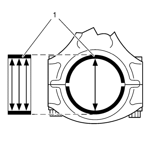
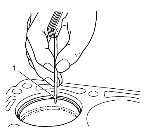
  4. Measure the connecting rod bearing diameters at 3 points as shown (1). Use an internal measuring device.
  5. Calculate the average connecting rod inner diameter.
  6. Formula: 1. result + 2. result + 3. result / 3


    2189634
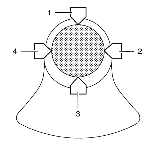
  7. Measure the connecting rod journal diameter at 2 points between 1 and 3 and between 2 and 4. Use a micrometer gauge.
  8. Calculate the average connecting rod journal diameter.
  9. Formula: 1. result + 2. result / 2.

  10. Subtract the average connecting rod journal diameter from the average connecting rod bearing diameter in order to determine the connecting rod bearing clearance.
  11. The clearance should be 0.013 mm - 0.061 mm (0.0005 in - 0.0024 in)


&#169© Copyright Chevrolet. All rights reserved