Master Cylinder Replacement
Removal Procedure
Warning: Refer to Brake Fluid Irritant Warning in the Preface section.
Caution: Refer to Brake Fluid Effects on Paint and Electrical Components Caution in the Preface section.
Note: The transmission must be in the PARK position, the power button in the OFF position, and the brakes not applied to ensure the brake modulator and high pressure accumulator (HPA) pressure relief occurs. This process will take approximately 1 to 3 minutes.
- Place the transmission in PARK.
- Place the power button in the OFF position.
- Remove the remote keyless entry (RKE) transmitter and close all of the vehicle doors.
Note: During the pressure relief process, the fluid level in the master cylinder reservoir will rise. Do not remove the master cylinder reservoir cap during the pressure relief process.
- Wait approximately 3 minutes for the HPA pressure relief to occur.
- Disable the high voltage system. Refer to High Voltage Disabling .
- Remove the bolt and position aside the engine wiring junction block.
- Remove the front suspension strut housing brace. Refer to Front Suspension Strut Housing Brace Replacement .
- Remove the brake fluid from the master cylinder reservoir and discard into an approved container.
- Disconnect the brake fluid level indicator electrical connector.
- Remove the brake master cylinder reservoir supply and return hoses. Refer to Brake Master Cylinder Reservoir Hose Replacement .
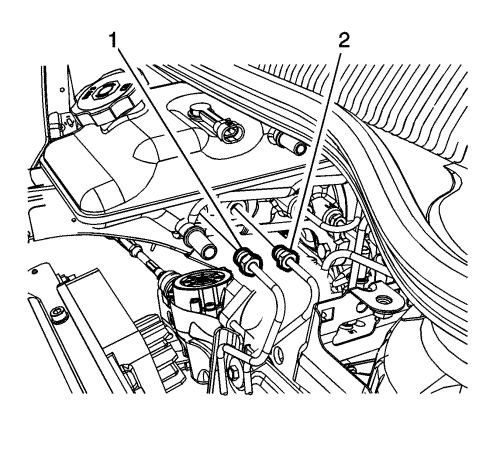
- Remove the left front brake pipe (1) and the right front brake pipe (2) from the master cylinder.
- Cap the brake pipe fittings and plug the master cylinder outlet ports to prevent brake fluid loss and contamination.
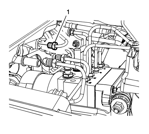
- Remove the left front secondary brake pipe (1) from the master cylinder.
- Cap the brake pipe fitting and plug the master cylinder outlet port to prevent brake fluid loss and contamination.

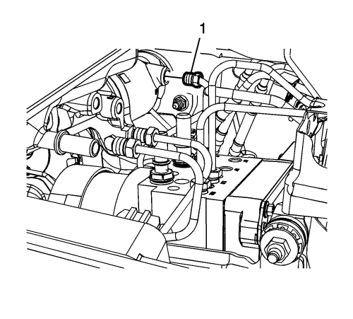
- Remove the right front secondary brake pipe (1) from the master cylinder.
- Cap the brake pipe fitting and plug the master cylinder outlet port to prevent brake fluid loss and contamination.
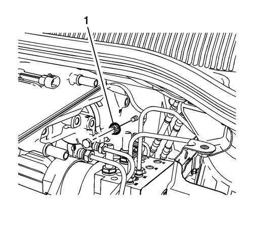
- Remove the master cylinder primary brake pipe (1) from the master cylinder.
- Cap the brake pipe fitting and plug the master cylinder outlet port to prevent brake fluid loss and contamination.
Note: Do not reuse the master cylinder nuts.
- Remove and discard the 2 master cylinder nuts (1).
- Remove the brake master cylinder.
Installation Procedure
- Bench bleed the brake master cylinder. Refer to Master Cylinder Bench Bleeding .
- Install the brake master cylinder to the vehicle.
Caution: Refer to Fastener Caution in the Preface section.
Note: Install new master cylinder nuts.
- Install 2 new master cylinder nuts (1) and tighten to 22 N·m (16 lb ft).
- Install the master cylinder primary brake pipe (1) and tighten the fitting to 23 N·m (17 lb ft).
- Install the right front secondary brake pipe (1) and tighten the fitting to 23 N·m (17 lb ft).
- Install the left front secondary brake pipe (1) and tighten the fitting to 23 N·m (17 lb ft).
- Install the left front brake pipe (1) and the right front brake pipe (2) and tighten the fittings to 23 N·m (17 lb ft).
- Install the brake master cylinder reservoir supply and return hoses. Refer to Brake Master Cylinder Reservoir Hose Replacement .
- Connect the brake fluid level indicator electrical connector.
- Install the front suspension strut housing brace. Refer to Front Suspension Strut Housing Brace Replacement .
- Install the engine wiring junction block and bolt.
- Enable the high voltage system. Refer to High Voltage Enabling .
- Fill the master cylinder reservoir. Refer to Master Cylinder Reservoir Filling .
- Bleed the hydraulic brake system. Refer to
Hydraulic Brake System Bleeding : Pressure .
| © Copyright Chevrolet. All rights reserved |


