Callout
| Component Name
|
|
Danger: Always perform the High-Voltage Disabling procedure prior to servicing any High Voltage component or connection. Personal Protection Equipment (PPE) and proper procedures must be followed. The High-Voltage Disabling procedure will perform the following tasks:
| • | Identify how to disable high voltage. |
| • | Identify how to test for the presence of high voltage. |
| • | Identify conditions under which high voltage is always present and personal protection equipment (PPE) and proper procedures must be followed. |
| • | Safety goggles with appropriate side shields when within 15 metres (50 feet) of the vehicle, either indoors or outdoors. |
| • | Certified and up-to-date Class "0" Insulation gloves rated at 1000 V with leather protectors. |
| - | Visually and functionally inspect the gloves before use. |
| - | Wear the Insulation gloves with leather protectors at all times when working with the high-voltage battery assembly, whether the system is energised or not. |
Preliminary Procedures
- Disable the high-voltage system. Refer to High Voltage Disabling .
- Remove the accessory DC power control module cooling air inlet duct. Refer to Accessory DC Power Control Module Cooling Air Inlet Duct Replacement .
- Remove the accessory DC power control module cooling air duct. Refer to Accessory DC Power Control Module Cooling Air Duct Replacement .
- Disconnect the negative and positive cables from the accessory DC power control module. Refer to Battery Positive and Negative Cable Replacement .
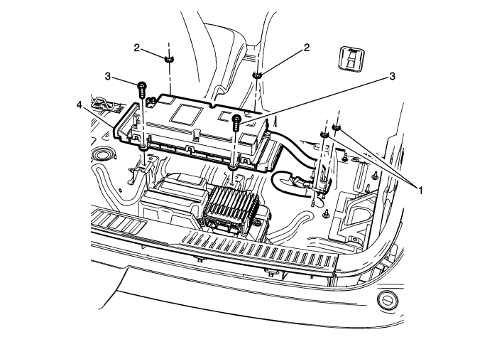
|
1
| Battery Positive and Negative Cable Nut (Qty: 2)
Caution: Refer to Fastener Caution in the Preface section.
Tighten
9 N·m (80 lb in) |
2
| Accessory DC Power Control Module Nut (Qty: 2)
Caution: Refer to Fastener Caution in the Preface section.
Tighten
22 N·m (16 lb ft) |
3
| Accessory DC Power Control Module Bolt (Qty: 2)
Tighten
19 N·m (14 lb ft) |
4
| Accessory DC Power Control Module
Procedure
- Raise the vehicle to access the connector. Refer to Lifting and Jacking the Vehicle .
- Disconnect the electrical connector underneath the vehicle.
|