Volt |
||||||||
|
|
|
|||||||
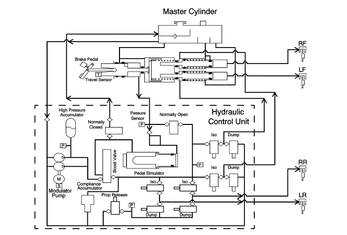
The hydraulic brake system consists of the following:
Hydraulic Brake Master Cylinder Fluid Reservoir: Contains supply of brake fluid for the hydraulic brake system. Provides for brake fluid to be drawn back into and vented back from the master cylinder primary piston and secondary pistons. Also provides for brake fluid to be drawn into the motor driven pump and high pressure accumulator (HPA) areas of the brake modulator assembly, and vented back from various areas of the modulator assembly as needed. Provides markings for both the MIN and MAX parameters of the pressurised or operating range; and for the maximum depressurised or system OFF level.The brake assist system consists of the following:
Brake Pedal: Receives, multiplies and transfers brake system input force from the driver.When the power button is placed in ON/RUN or a remote function actuation (RFA) commands remote START, the brake modulator assembly activates and pressurises brake fluid for use at the wheel apply circuits as needed.
The brake modulator assembly incorporates a motor driven pump which is activated as required to draw brake fluid directly from the master cylinder reservoir, lowering the brake fluid level in the reservoir into the pressurised, or operating, range. The pump pressurises and delivers the brake fluid to the high pressure accumulator (HPA) to store for use as necessary. Sensor data of HPA fluid pressure is used by the modulator to operate the pump to maintain the pressure of the brake fluid at the HPA within operating range. Working pressure of the HPA stored fluid is 140-180 bar (2030-2610 psi). Peak allowed pressure is 200 bar (2900 psi). Pressure relief is vented back to the master cylinder reservoir.
Brake system mechanical input force from the driver is multiplied by the brake pedal and transferred by the pedal pushrod to the hydraulic brake master cylinder. This mechanical force is converted into hydraulic pressure by the primary piston of the master cylinder. The pressurised brake fluid from the primary piston is delivered to the brake modulator assembly and is directed within the modulator to the brake pedal feel simulator.
To allow operation of the pedal feel simulator, the brake modulator assembly energises and then closes the normally open (NO) valve to direct brake fluid only to the pedal feel simulator. The brake modulator also energises and opens a normally closed (NC) valve to allow brake fluid to escape from the backside of the brake pedal feel simulator to the master cylinder reservoir, allowing the simulator piston to move. The pedal feel simulator incorporates a spring which causes increasing brake pedal effort and feedback through the master cylinder, providing brake pedal feel to the driver.
The brake modulator assembly uses sensor data of the brake pedal and pushrod travel and the master cylinder input fluid pressure to determine the amount of braking performance requested by the driver.
Based on the amount of braking action requested by the driver and sensor data inputs of fluid pressure throughout the brake modulator assembly passageways, the modulator uses a boost valve to continuously provide the optimal fluid pressure for use by the wheel apply circuits. The modulator assembly uses the boost valve to both build and relieve pressure within the wheel apply circuits. The boost valve meters the flow of pressurised brake fluid from the HPA to build pressure and relieves pressure as needed by venting fluid through the energised, and open, NC valve to the master cylinder reservoir. The brake modulator assembly also controls various valves in a way similar to a traditional brake modulator, to blend and modulate delivery of brake fluid to the wheel apply circuits, to achieve optimal balance and brake system output performance. The brake modulator delivers brake fluid to the wheel apply circuits as follows:
| • | Through isolation valves directly to the rear wheel apply circuits |
| • | Through isolation valves directly to the secondary pistons of the master cylinder |
| • | The secondary pistons of the master cylinder then delivers pressurised brake fluid directly to the front wheel apply circuits |
Pressurised brake fluid is delivered to the wheel apply hydraulic components through the brake pipes and flexible hoses. The wheel apply components then convert the hydraulic pressure back into mechanical force which presses the brake linings against rotating brake system components to slow the vehicle through friction braking.
When the power button is placed in the OFF position and the brake pedal is not applied, the system will deactivate and depressurise. As the system begins to depressurise, brake fluid will discharge from the HPA and vent back into the master cylinder reservoir. This will cause the brake fluid level in the master cylinder reservoir to rise to the depressurised or system OFF range. The system may take up to 3 minutes to fully depressurise.
If the brake pedal is applied before the system has fully depressurised, the brake modulator will maintain the pressure available at the moment of the brake apply until the brake pedal is released. This will increase the amount of time required for the system to depressurise.
Regenerative Braking Function: During a regenerative braking event, the powertrain is used to create drag or torque braking through the drive axle, against the forward motion of the vehicle, while providing a charging function for the batteries.The brake modulator assembly and the powertrain system controllers are in constant communication with each other. Each system is monitoring various system, sensor data, and driver inputs. Working together, a determination is made as to when the most appropriate opportunity for regenerative braking will occur. The brake modulator will request from the powertrain controllers the amount of torque braking that is available from the powertrain to be delivered through the drive axle. If the powertrain controllers in conjunction with the brake modulator have determined to perform a regenerative braking event, the brake modulator will request a specific amount of regenerative or torque braking to be provided from the powertrain.
Simultaneously, the brake modulator continuously evaluates and provides the correct blend of friction braking from the non-drive axle, and provides the correct blend of regenerative or torque braking and friction braking from the drive axle to provide the most efficient amount of regenerative braking and charging for the needs of the powertrain. All the while, providing optimal braking balance and providing the correct blend and amount of overall vehicle braking action requested by the driver through a brake pedal apply.
Deactivated System: If the brake modulator assembly is powered down either by placing the power button in the OFF position and not applying the brake pedal, or through a system power source failure or if the modulator detects certain critical faults, the system will operate as follows:Brake system mechanical input force from the driver is multiplied by the brake pedal and transferred by the brake pedal pushrod to the hydraulic brake master cylinder. This mechanical force is converted into hydraulic pressure by the primary piston of the master cylinder.
The pressurised brake fluid from the primary piston is delivered to the brake modulator assembly and is directed within the brake modulator to the wheel apply passageways, rather than to the pedal simulator.
Since the modulator is not energising the normally open (NO) valve to cause it to close and direct pressurised fluid only to the pedal simulator, the NO valve is open and directing fluid to both the pedal simulator and the wheel apply circuit passageways. To prevent any loss of pressure through the pedal simulator, or through the boost valve, the normally closed (NC) valve is closed since it is not energised by the modulator. Since the NC valve is closed, no fluid can escape from the backside of the simulator, thus preventing any movement of the piston within the pedal simulator and any subsequent loss of pressure. The same is true with the boost valve, since the NC valve is closed, no fluid can escape from the pressure relief side of the boost valve, thus preventing loss of pressure. The pressurised fluid is now delivered through the wheel apply circuit passageways within the modulator as follows:
| • | Through de-energised, open isolation valves directly to the rear wheel apply circuits |
| • | Through de-energised, open isolation valves directly to the secondary pistons of the master cylinder |
| • | The secondary pistons of the master cylinder then deliver pressurised brake fluid directly to the front wheel apply circuits |
If a hydraulic failure occurs in the boost circuit of the modulator during further pedal apply, the system will operate as follows:
The mechanical input force is applied further as the primary piston of the master cylinder directly contacts the secondary pistons, which then convert the mechanical force into hydraulic pressure. The pressurised brake fluid from the secondary pistons is delivered directly to the front wheel apply circuits.
| ©© Copyright Chevrolet. All rights reserved |


