Camshaft Inlet and Exhaust Sprocket Replacement
Special Tools
EN-955-1 Locking Pin
For equivalent regional tools, refer to Special Tools .
Removal Procedure
Danger: Always perform the High Voltage Disabling procedure prior to servicing any High Voltage component or connection. Personal Protection Equipment (PPE) and proper procedures must be followed.
The High Voltage Disabling procedure will perform the following tasks:
| • | Identify how to disable high voltage. |
| • | Identify how to test for the presence of high voltage. |
| • | Identify condition under which high voltage is always present and personal protection equipment (PPE) and proper procedures must be followed. |
- Disable the high voltage system. Refer to High Voltage Disabling .
- Drain the cooling system. Refer to Cooling System Draining and Filling .
- Disable the high voltage system. Refer to High Voltage Disabling .
- Remove the camshaft cover. Refer to Camshaft Cover Replacement .
- Remove both camshaft position actuator solenoid valves. Refer to
Camshaft Position Actuator Solenoid Valve Replacement : Exhaust → Intake .
- Adjust the engine to TDC. Refer to Camshaft Timing Chain Adjustment .
- Remove the engine mount bracket. Refer to Engine Mount Bracket Replacement - Right Side .
- Place a floor jack with block of wood under the oil sump.
- Remove engine support fixture. Refer Engine Support Fixture .
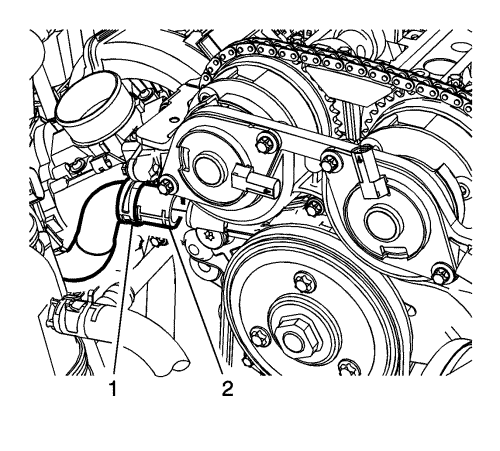
- Remove the heater water shutoff valve inlet hose clamp (1) at engine.
- Remove the heater water shutoff valve inlet hose (2) from engine.
- Disconnect the heater water shutoff valve inlet hose from the engine.
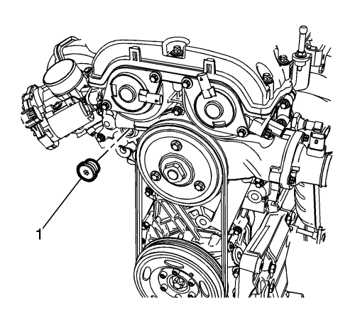
- Remove the timing chain tensioner plug (1) from the engine front cover.
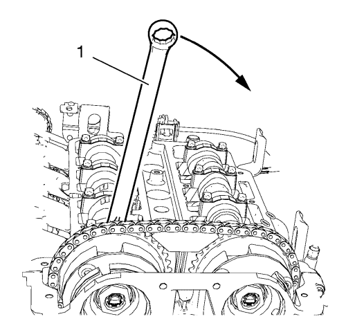
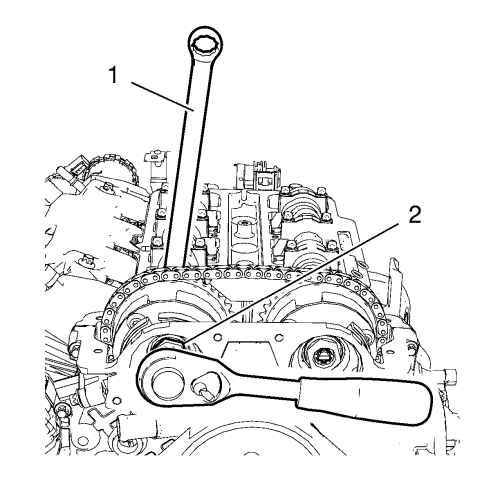
- Install a wrench (1) on the cast hexagonal portion of the inlet camshaft, rotate the camshaft toward the exhaust camshaft in order to apply tension.
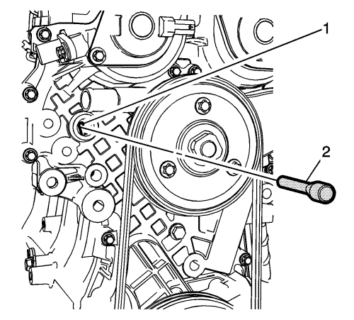
- Install EN-955-1 pin (2) to the timing chain tensioner bore (1).
- Remove the wrench from inlet camshaft.
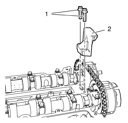
- Remove the 2 upper timing chain guide bolts (1).
- Remove the upper timing chain guide (2).
- Loosen the inlet camshaft sprocket bolt (2) while holding up the hexagon of the inlet camshaft with a wrench (1).
- Loosen the exhaust camshaft sprocket bolt while holding up the hexagon of the exhaust camshaft with a wrench.
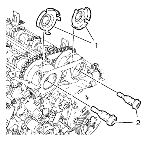
- Remove the camshaft sprocket bolts (2) and the camshaft position exciter wheels (1).
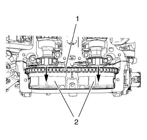
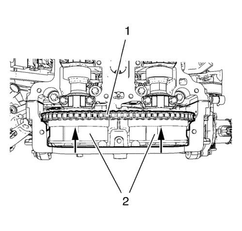
- Remove the camshaft sprockets (2) and timing chain (1) as one unit.
- Remove the inlet and exhaust camshaft sprocket.
- Allow the chain to rest on the front cover.
Installation Procedure
- Install the camshaft sprockets (2) and timing chain (1) as one unit.
- Install the camshaft position exciter wheels (1).
Caution: Refer to Fastener Caution in the Preface section.
- Install the camshaft sprocket bolts (2) and tighten to 50 N·mplus 45+15 degrees (37 lb ft) plus 45+15 degrees.
- Remove the EN-955-1 pin .
- Adjust the camshaft timing chain. Refer to Camshaft Timing Chain Adjustment .
- Install the upper timing chain guide (2).
- Install the upper timing chain guide bolts (1) and tighten to 8 N·m (71 lb in).
- Install the timing chain tensioner plug (1) and tighten to 50 N·m (37 lb ft).
- Install both camshaft position actuator solenoid valves. Refer to
Camshaft Position Actuator Solenoid Valve Replacement : Exhaust → Intake .
- Connect the heater water shutoff valve inlet hose (2) to the engine.
- Install the heater water shutoff valve inlet hose clamp (1).
- Install the engine mount bracket. Refer to Engine Mount Bracket Replacement - Right Side .
- Install the camshaft cover. Refer to Camshaft Cover Replacement .
- Fill the cooling system. Refer to Cooling System Draining and Filling .
- Enable the high voltage system. Refer to High Voltage Enabling .
| ©© Copyright Chevrolet. All rights reserved |


