Volt |
||||||||
|
|
|
|||||||
| Table 1: | Preliminary Procedures |
| Table 2: | Instrument Panel Electrical Centres Service Positioning |
| Table 3: | Communication Interface Module Bracket Service Positioning |
| Table 4: | Instrument Panel Tie Bar |
Note: All procedures must be followed in the order shown to be able to remove the instrument panel tie bar assembly.
|
Note: The instrument panel electrical centres are an integral part of the instrument panel wiring harness and are not a separate serviceable item.
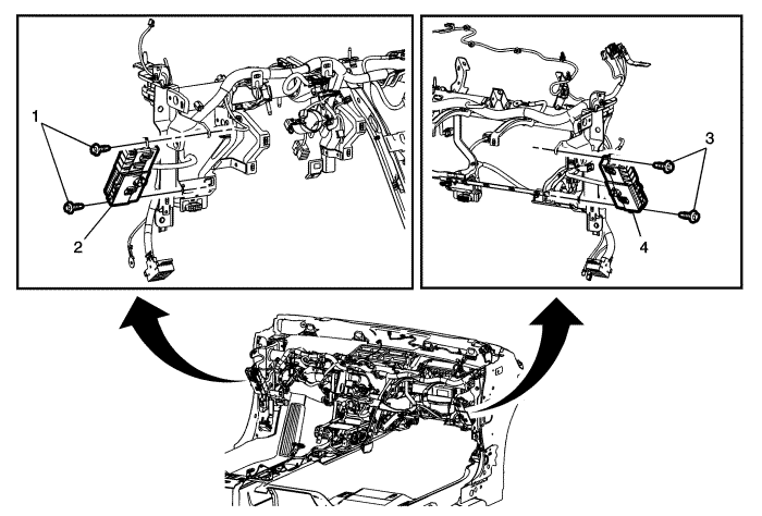
Callout | Component Name |
|---|---|
1 | Right Instrument Panel Electrical Centre Fasteners (Qty: 2) Caution: Refer to Fastener Caution in the Preface section. |
2 | Right Instrument Panel Electrical Centre Assembly ProcedurePosition the electrical centre assembly out of the way. |
3 | Left Instrument Panel Electrical Centre Fasteners (Qty: 2) |
4 | Left Instrument Panel Electrical Centre Assembly ProcedurePosition the electrical centre assembly out of the way. |
Note: It is not necessary to disconnect the electrical wiring to the modules or remove the modules from the communications interface module bracket when following the service positioning procedure.
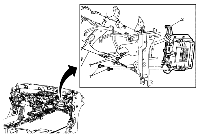
Callout | Component Name |
|---|---|
1 | Communication Interface Module Bracket Fasteners (Qty: 4) |
2 | Communication Interface Module Bracket Assembly ProcedurePosition the communication interface module bracket assembly out of the way. |
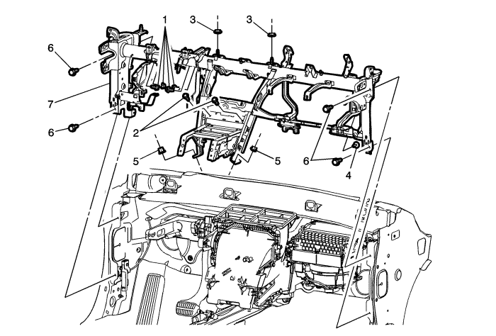
Callout | Component Name |
|---|---|
1 | Instrument Panel Tie Bar to Brake Pedal Bracket Bolts (Qty: 4) Caution: Refer to Fastener Caution in the Preface section. Tighten |
2 | Instrument Panel Tie Bar to HVAC Module Bolts (Qty: 2) |
3 | Instrument Panel Tie Bar to HVAC Module Nuts (Qty: 2) |
4 | Instrument Panel Tie Bar to HVAC Module Bolt Tip |
5 | Instrument Panel Tie Bar to Front Floor Tunnel Panel Nuts (Qty: 2) Tighten |
6 | Instrument Panel Tie Bar to Vehicle Body Bolts (Qty: 4) Tighten |
7 | Instrument Panel Tie Bar Assembly Procedure
|
| © Copyright Chevrolet. All rights reserved |


